Volume 8, No. 4, May-June 2017
International Journal of Advanced Research in Computer Science
RESEARCH PAPER
Available Online at www.ijarcs.info
ISSN No. 0976-5697
Comparative Analysis of Dispersion Compensation Techniques for Hybrid WDM/TDM
Passive Optical Network
Garima Mahajan and Harmandar Kaur
Department of Electronics and Communication Engineering, GNDU, RC, Jalandhar, India
Abstract: Due to the growth of web and multimedia services Passive Optical Network (PON) come back to the leading edge of the research field. Optical networks play a important role by implementing optical fibre using Passive Optical Networks. Network service provider largely uses the Time Division Multiplexing and Wavelength Division Multiplexing based PON. Time Division Multiplexing (TDM) and Wavelength Division Multiplexing (WDM) are the foremost common multiplexing techniques. Both of these techniques has its own benefits and drawbacks. As Time Division Multiplex is capable to serve only a small variety of participants with low speed however for affordable prices. On the opposite side the Wavelength Division Multiplexing can serve a huge variety of participants but its price is much higher. In light of these contrasting properties there is an attempt to make a Hybrid WDM/TDM network that would have positive characteristics of each of these multiplexes and will also meet the characteristics of the Passive Optical Network (PON). In this paper techniques Hybrid WDM/TDM has been investigated for the three dispersion compensation techniques (pre, post and symmetrical) using the Dispersion Compensating Fibers (DCF). The performance has been compared on the basic of different parameters at the receiving end. Optisystem 7.0 is used for designing and simulation of the proposed system.
Keywords: Passive Optical Network (PON), Optical Line Terminal, Optical Network Unit (Wavelength Division Multiplexing (WDM), Time Division Multiplexing (TDM), Bit Error Rate (BER), Quality Factor, Dispersion Compensating Fibers (DCF).
1. INTRODUCTION
Hybrid (WDM/ TDM) PON is the system which uses both WDM and TDM techniques. The benefits of both the multiplexing techniques are provided to the end users where an Optical Line Terminal (OLT) is located at the Central Office (CO) and is connected to many Optical Network Units (ONUs) located at the customer’s premises through one or multiple 1:N optical splitters as shown in fig 1. The network between the OLT and the ONU is static i.e it does not require any power supply [1-2].
Fig.1: Passive Optical Network
WDM-PON is a technique in which each ONU uses a distinct wavelength, i.e different wavelength in each direction to communicate with the OLT. The TDM is a technique in which a specific time slot of a finite duration is allocated to each station in the network for its transmission in a given time interval. When we use the WDM/TDM integrated concept, each ONU uses a different wavelength which is allotted to them by using time division multiplexing either statically or dynamically. Hybrid WDM/TDM PON is a promising next generation broadband access scheme. In this paper, previous work has been
enlarged by calculating the performance of hybrid WDM/TDM PON in terms of Q-factor and BER [3].
2. SYSTEM ARCHITECTURE
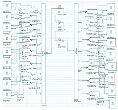
The simplified architecture of WDM/TDM PON consists of nine users as shown in fig.2. In this, the concepts of WDM and TDM are united to upgarde the efficiency of PON. Each ONU uses a definite wavelength in each direction to communicate with the OLT. The simulation of hybrid WDM/TDM PON is evaluated by using the optisystem software.
For the architecture of Hybrid WDM/TDM PON Erbium Doped Fibre Amplifier (EDFA) are used. EDFA are very much definitive for long distance transmission using single or multi-wavelength sources because of their wide bandwidth and optimum BER.
Fig.3: Hybrid WDM/TDM PON transmitter
[image:2.595.324.551.53.139.2]The transmitter of Hybrid WDM/TDM PON architecture is as shown in fig 3. The Pseudo Random Bit Sequence Generator (PRBS) will generate bit sequences (either 1 or 0) in random manner. We assume that this is the information that is to be transmitted. This bit sequence generator is then fed into a NRZ pulse generator which transforms the bit sequences into NRZ pulses. These pulses are modulated using a Mach-Zender Modulator with the carrier power coming from the laser sources (laser frequency to be 193.9THz since it corresponds to 1550nm which is an optimal operating wavelength [3].
Fig.4: Hybrid WDM/TDM PON receiver
On the receiver side as shown in fig.4, the photo detector converts the optical signal into electrical signal. This signal is then passed through a low pass Bessel’s filter and then through a 3R regenerator. The Bessel’s filter considerably reduces the peak overshoot. The regenerator reconstructs and regenerates the signal and feeds it into a BER analyser where the output signal can be visualised [3].
Table 1: Simulation Parameters and their Values
COMPONENT PARAMETER
TYPE VALUE
Light source Frequency 193.1-9 THz Power 2 dBm PRBS generator Bit rate 2.5 Gbps Photo detector Responsisvity 1 A/W
Dark current 10 nA Modulator Modulation
format
NRZ
Operating wavelength
1550 nm
Optical fiber Fiber length 50 km
Gain 5 m
Dispersion compensation is accomplished by three contrasting schemes depending upon the position of DCF: i. Pre-compensation
ii. Post-compensation
iii. Symmetrical-compensation
In pre-compensation scheme the DCF is arranged before the standard single mode fiber (SSMF) to compensate the positive dispersion in SSMF.
[image:2.595.46.271.123.258.2] [image:2.595.50.266.444.578.2]In post-compensation scheme. the DCF is arranged after the SSMF to compensate the positive dispersion in SSMF. In symmetrical-compensation scheme both the schemes (pre-, post-compensation) are used i.e. DCF is placed before as well as after the SSMF to accomplish the dispersion compensation [4-7].
Table 2: Fiber Parameters and their Values
PARAMETERS SMF DCF
Length (km) 30 60
Attenuation (db/km) 0.2 0.6 Dispersion (ps/nm/km) 17 -80 Dispersion slop (ps/nm^2/km)
0.08 0.3
Differential group delay (ps/km)
0.5 0.5
The simulation setups of three dispersion schemes are shown in Fig.5
[image:2.595.337.539.485.673.2](b) Post-compensation
[image:3.595.38.239.52.404.2](c) Symmetrical-compensation
Fig.5 Simulation setup of pre, post and symmetrical dispersion compensation
3. RESULTS
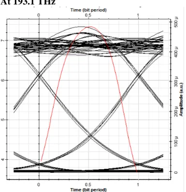
The eye diagrams for the pre-, post- and symmetrical-compensation are shown in Fig.6, Fig.7 and Fig8 and the values for the first, third, fifth and last user are tabulated into Table 3 and are compared.
At 193.1 THz
At 193.3 THz
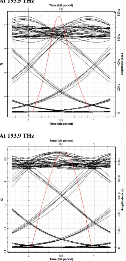
At 193.5 THz
[image:3.595.38.231.536.735.2]At 193.9 THz
At 193.1 THz
At 193.3 THz
At 193.5 THz
At 193.9 THz
Fig.7 Eye diagrams of post-compensation at distinct channels
At 193.1 THz
At 193.5 THz
At 193.9 THz
Fig.8 Eye diagrams of symmetrical-compensation at distict channels
Table 3. Comparison of three schemes at distinct channels.
At 193.1 THz
Pre compen sation Post compensati on Symmetric al compensati on Q-factor(db) 7.3450 6
7.52578 7.59746
BER 1.0222 6e-013
2.56376e-014
1.50929e-014 Eye height 0.0002
44215 8.36553e-005 0.0004313 97
At 193.3 THz
Q-factor(db)
7.17407 7.20425 7.73974
BER 3.6327e-013
2.84303e -013
4.97817e-015 Eye height 0.000251
97
8.20586e -005
0.0004151 01
At 193.5 THz
Q-factor(db)
7.8629 7.09715 7.34437
BER 1.87517e-015 6.22245e-013 1.02609 e-013 Eye height
0.000274064 7.94735e-005
0.00036 0308
At 193.9 THz
Q-factor(db)
7.63728 7.06718 4.39117
BER 1.10805e-014
1.20053e -612
3.29438e-006 Eye height 0.000281
234 7.82218e -005 0.0001409 37 4. CONCLUSION
In this paper the performance of Hybrid WDM/TDM PON is evaluated in terms of Q-factor and BER. The three dispersion compensation schemes using DCF (pre-, post- and symmetrical-compensation) are compared in terms of BER and Q-factor and eye height.
5. REFRENCES
[1] Frank J. Effenberger et. al., “Standardization Trends and Prospective Views on the Next Generation of Broadband Optical Access Systems,” IEEE Journal on selected areas in communications, vol.28, no.6, August 2010.
[2] Md. Shamim Ahsan et. al., “Migration to the Next Generation Optical Access Network,” JOURNAL OF NETWORKS, Vol. 6, No.1, pp. 18-25, January 2011.
[3] G. Aarthi et. al., “Comparative Analysis of the Present and the Future Technologies for WDM-PON and WDM-TDM-PON Systems,” International Journal of Applied Engineering Research, Vol. 8, No. 19 pp. 2575-2580, 2013.
[4] Gurinder Singh et.al., “Investigations on order and width of RZ super Gaussian pulse in different WDM systems at 40 Gb/s using dispersion compensating fibers,” Optik 125, pp. 4270-4273, 2014.
[5] R.S. Kaler, A.K. Sharma, T.S. Kamal, “Comparison of pre-, post- and symmetrical- dispersion compensation schemes for 10 Gb/s NRZ links using standard and dispersion compensated fibers,” Optics. Communication, 209, pp. 107–123, 2002. [6] Bo-Ning HU, Wang Jing, Wang Wei, Rui-Mei Zhao, “Analysis
on Dispersion Compensation with DCF based on Optisystem,” IEEE 2nd International Conference on Industrial and Information Systems, pp. 40-43, 2010.
[image:5.595.37.244.59.485.2]