University of South Carolina
Scholar Commons
Theses and Dissertations
2017
Modeling Battery Performance Due To Volume
Change In Porous Electrodes Due To Intercalation
Taylor R. Garrick
University of South Carolina
Follow this and additional works at:https://scholarcommons.sc.edu/etd Part of theChemical Engineering Commons
This Open Access Dissertation is brought to you by Scholar Commons. It has been accepted for inclusion in Theses and Dissertations by an authorized administrator of Scholar Commons. For more information, please [email protected].
Recommended Citation
MODELING BATTERY PERFORMANCE DUE TO VOLUME CHANGE IN POROUS
ELECTRODES DUE TO INTERCALATION
by
Taylor R. Garrick
Bachelor of Science in Engineering University of South Carolina, 2013
Submitted in Partial Fulfillment of the Requirements
For the Degree of Doctor of Philosophy in
Chemical Engineering
College of Engineering and Computing
University of South Carolina
2017
Accepted by:
John W. Weidner, Major Professor
Donna A. Chen, Committee Member
John R. Monnier, Committee Member
Sirivatch Shimpalee, Committee Member
ii
iii
ACKNOWLEDGEMENTS
First of all, I would like to thank my advisor Dr. John W. Weidner for his continued support
of my studies and academic goals. His influence during my undergraduate studies motivated me to
pursue graduate studies, and his knowledge and novel research cemented my desire to continue
these studies with his research group at the University of South Carolina. His mentorship style has
enabled me to explore a variety of different research areas within electrochemical engineering, and
gain a great amount of experience through external and collaborative research, which has benefitted
me through professional growth. I would also like to thank Dr. Donna A. Chen and Dr. John R.
Monnier who through their collaborative research with our group illustrated the many benefits of
cross-discipline collaboration. I appreciate their probing questions and guidance throughout my
graduate studies. Also, Dr. Sirivatch Shimpalee, who has been a great support through his daily
discussions and computational expertise. I have received much support from researchers at
Lawrence Berkeley National Laboratory and Argonne National Laboratory, including Dr. Kenneth
Higa, Dr. Yiling Dai, and Dr. Venkat Srinivasan. Their assistance with battery parameter estimation
and modeling has been crucial to the completion of my work. I would also like to thank my friends
and colleagues for their insight and assistance, particularly Dr. John A. Staser, Dr. Bahareh Alsadat
Tavakoli Mehrabadi, Kumud Kanneganti, and Cody Wilkins.
Finally, I am very grateful to my family: My parents for their financial and emotional
support, my siblings for their encouragement, and my wife, for her loving support of me in all that
iv ABSTRACT
The demand for energy continues to increase as the economies of developing
countries become more modern and show an increased need for a reliable energy
infrastructure in order to meet the increased demand associated with a large and more
mobile population. An increased demand puts a strain on all sectors, however it is
specifically noticeable in the transportation sector where a significant portion of the fuel
utilized for transportation comes from petroleum and other fossil fuels. Recently, using
alternative forms of energy for transportation has become reality, and in turn, using
electricity as a transportation fuel has gained significant momentum, specifically for use in
battery-only rechargeable vehicles. Significant strides have been made to improve the
range, cost, and fueling times of these battery-only vehicles through the improvement of
the design and control of cells, and several automobile manufacturers are releasing battery
powered vehicles with price points that target the general public. New materials have also
been examined in order to increase the energy densities of these batteries in order to
increase the range of battery powered vehicles, and decrease the volume displacement in
the vehicle powertrain.
Some of the new battery electrode materials see significant expansion during
cycling, which results in stress linked to capacity fade, battery failure, separator
deformation, and electrolyte degradation. In order to accurately predict the behavior of
complicated electrochemical devices undergoing a variety of different structural and
v
processes, electrochemical phenomena, mechanical stresses, and structural deformations
must be developed in order to predict the associated effects on the operation of an
electrochemical system. There are many models in the literature that can predict the
electrochemical performance of devices with porous electrodes under a variety of operating
and design conditions, however, in many of these models, when the porosity of the porous
electrode is accounted for it is assumed to be a function of current density, since the volume
changes seen during the intercalation reaction can be small. However, electrodes that have
been developed in recent years show battery systems that have significant volume changes
during intercalation. The battery model developed here incorporates aspects of a porous
electrode model that accounts for the stresses that build up in porous electrodes due to
volume change in the active material. The material balances here are coupled to
stress-strain relationships that are derived from rock mechanics, in which the deformation of the
porous rock occurs during thermal expansion similar to the deformation of the porous
electrode that occurs during intercalation. This allows for a prediction of dimensional
changes and porosity changes in a porous electrode and the associated effect on battery
vi
TABLE OF CONTENTS
ACKNOWLEDGEMENTS ... iii
ABSTRACT ... iv
LIST OF TABLES ... viii
LIST OF FIGURES ... ix
CHAPTER 1: INTRODUTION ... 1
CHAPTER 2: LITERATURE REVIEW ... 6
CHAPTER 3: MODELING VOLUME CHANGE DUE TO INTERCALATION INTO POROUS ELECTRODES ... 14
Model Development ... 15
Results and Discussion ... 20
Conclusions ... 23
Symbols ... 25
CHAPTER 4: MODELING VOLUME CHANGE IN DUAL INSERTION ELECTRODES ... 36
Model Development ... 39
Results and Discussion ... 45
Conclusion ... 52
Symbols ... 53
CHAPTER 5: MODELING BATTERY PERFORMANCE DUE TO INTERCALATION DRIVEN VOLUME CHANGE IN POROUS ELECTRODES ... 64
Model Development ... 65
vii
Additional Equations ... 78
Symbols ... 80
REFERENCES ... 94
APPENDIX A. STANDARD CONDUCTIVITY OBTAINED FROM LBNL ... 105
APPENDIX B. DIFFUSIVITY OBTAINED FROM LBNL ... 106
viii
LIST OF TABLES
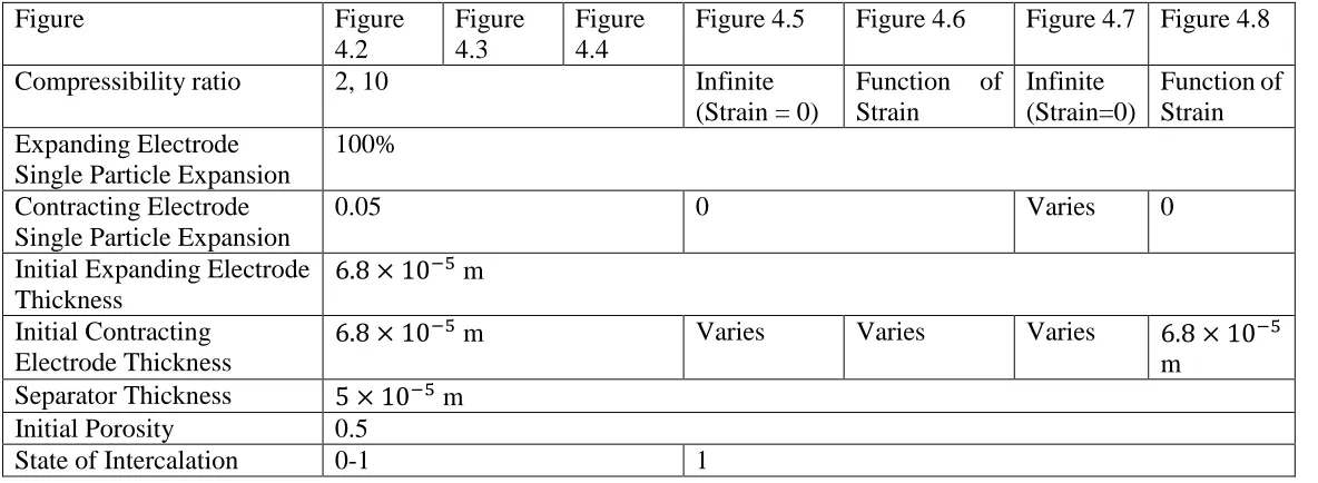
Table 4.1. List of parameters used with Equation 8, 9, and 10 for Figures 4.2-4.9 ... 55
ix
LIST OF FIGURES
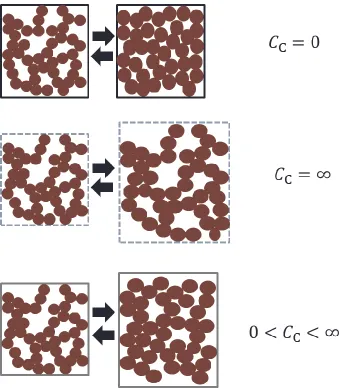
Figure 3.1: Depicts three cases with varying casing compressibility. Case #1 when the porous electrode is enclosed within an infinitely stiff casing, during intercalation there is no change in the volume of the electrode (g = 0). Case # 2 when the porous electrode is enclosed in an infinitely complaint casing, during intercalation there is only change in dimension of the electrode and the porosity of the electrode does not change (g = 1). Case # 3 when the porous electrode is enclosed in a finitely elastic casing, during intercalation both the dimensions and the porosity of the electrode change (0 < g < 1). ... 28
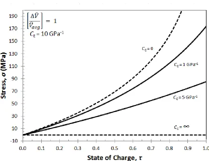
Figure 3.2: Stress building up in a porous electrode during intercalation for four values of the casing compressibility: rigid casing (CC=0); infinitely compliant casing (CC=∞); and two intermediate values. ... 29
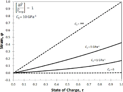
Figure 3.3: Strain in a porous electrode during intercalation for four values of the casing compressibility: rigid casing (CC= 0); infinitely compliant casing (CC = ∞); and two intermediate values. ... 30
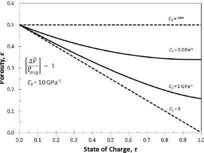
Figure 3.4: Porosity in a porous electrode during intercalation for four values of the casing compressibility: rigid casing (CC= 0); infinitely compliant casing (CC = ∞); and
two intermediate values. Initial porosity, ε0 = 0.5 ... 31
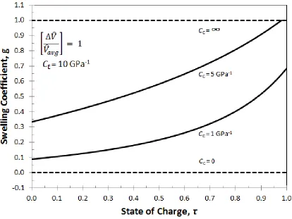
Figure 3.5: The swelling coefficient for a porous electrode during intercalation for four values of the casing compressibility: rigid casing (CC = 0); infinitely compliant casing (CC = ∞); and two intermediate values. ... 32
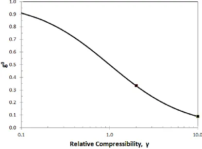
Figure 3.6: The initial swelling coefficient plotted as a function of the relative compressibility of a porous electrode, compared to that of the casing. (γ = CE/CC) ... 33
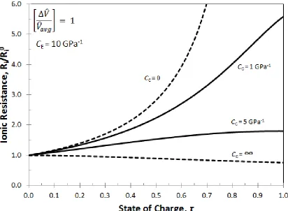
Figure 3.7: The ionic resistance in a porous electrode during intercalation for four values of the casing compressibility: rigid casing (CC = 0); infinitely compliant casing
(CC= ∞); and two intermediate values. ... 34
x
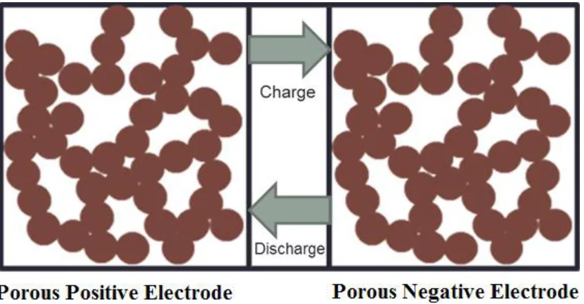
Figure 4.1: Illustration of battery setup. Porous positive electrode separated from the porous negative electrode by an incompressible separator. Electrodes and separator are not shown to scale. ... 56
Figure 4.2: Stress generation from single electrode model seen Ref. [1] (dotted lines) compared to stress generation from the two electrode model developed in this work (solid lines). State of intercalation for two electrode model based on the state of intercalation for the expanding electrode. ... 57
Figure 4.3: Strain development from single electrode model seen in Ref. [1] (dotted lines) compared to strain development in the expanding electrode from the two electrode model in this work (solid lines) ... 58
Figure 4.4: Porosity change during intercalation from single electrode model seen in Ref. [1] (dotted lines) compared to strain development in the expanding electrode from the two electrode model in this work (solid lines) ... 59
Figure 4.5 Dimensionless stress as a function of the electrode compressibility ratio. L+ and
L- represent the initial length of the expanding and contracting electrode
respectively ... 60
Figure 4.6: Dimensionless stress as a function of the final casing strain. L+ and L- represent the initial length of the expanding and contracting electrode respectively ... 61
Figure 4.7: Dimensionless stress as a function of the single particle expansion ratio. L+ and L- represent the initial length of the expanding and contracting electrode respectively. ■ and ● represent two example cases ... 62
Figure 4.8: Porosity of the expanding electrode at the final state of intercalation as a function of the dimensionless stress in the system. Initial porosity is assumed to be 0.5... 63
Figure 5.1: A schematic of the battery system modeled here. It involves a porous positive electrode, a separator, and a Li foil negative. The dark circles in the porous electrode represents the active intercalation material and the white space is the electrolyte. This schematic is not shown to scale ... 84
Figure 5.2: Strain distribution during discharge. CC+
C is 2 indicating a casing that is 2 times as rigid as the electrode undergoing expansion. Rate is 1C. Discharge interval is 1/5 of overall discharge obtained at the 1C rate. Single particle expansion is 100%. 85
Figure 5.3: Strain distribution at the end of discharge as a function of dimensionless length and CC+
C . Four different values of
C+
xi
Figure 5.4: Strain distribution at the end of discharge as a function of dimensionless length and discharge rate. Many different discharge rates are shown here. From right to left: C/50, C/2, C, 2C, 5C, 10C. Positive electrode single particle expansion during intercalation is 100%. C+
CC is 2 ... 87
Figure 5.5: Overall porosity of the electrode as a function of dimensionless discharge capacity. The only difference between discharge rates is the point at which discharge ceases. The relative rigidity of the casing material compared to the positive electrode under consideration varies (CC+
C values of 0.1, 1, 2, and 10). The positive electrode single particle expansion during intercalation is 100% ... 88
Figure 5.6: Porosity during discharge at a 1C discharge rate and C+/CC of 2. Single particle expansion is 100%. ... 89
Figure 5.7: Porosity at the end of discharge at 1C discharge rate for four differentCC+ C: 0.1, 1, 2, 10. Single particle expansion is 100% ... 90
Figure 5.8 Porosity at the end of discharge for different rates: C/50, C/2, C, 2C, 5C, 10C.
C+
CC is 2. Single particle expansion is 100% ... 91
Figure 5.9: Reaction Distribution in the expanding electrode during discharge. CC+
C is 2 and the single particle expansion is 100% ... 92
Figure 5.10: Cell potential as a function of dimensionless discharge capacity for 3 different discharge rates (C/2, C, and 2C) illustrating the effect of changing the rigidity of the casing material relative to the rigidity of the positive electrode under consideration (0.1, 1, 2, 10 CC+
1 CHAPTER 1
INTRODUCTION
Due to the increase in energy demands in developing nations around the world,
batteries that show an increased energy density have been the subject of much research in
order to extend the operating time of consumer electronics and the range of new battery
powered electric vehicles. The Li-ion battery has emerged during this time as the premier
energy storage chemistry used in batteries for portable electronic devices as well as electric
only battery vehicles due to the ability of many anode and cathode materials to incorporate
large amounts of lithium into their structures. However, as the electric vehicle
transportation market continues to grow, the need for batteries with higher energy density
and longer cycle life is needed. This development of higher energy density materials has
not been without setbacks[2] due to safety concerns[3-6], however, a renewed focus on
safety has been implemented in newer batteries utilizing these high energy density
materials.
Due to the recent commercial and government sector success of high energy density
batteries, high performance electrode materials, separators, electrolytes, and new cell and
stack designs are being actively developed. In commercial lithium-ion batteries, the most
widely used positive electrode materials are typically metal oxides such as LiCoO2[7-11]
or LiMnO2[12-15] and the most widely used negative electrode material is graphite[7, 11,
2
During the intercalation reaction, lithium ions diffuse[20, 22-25] from the electrolyte into
the active material and insert into the lattice structure of the active material, such as
LiCoO2. However, with some high expansion anode materials, such as silicon and tin, Li
forms an alloy during the intercalation process, which involves the breaking of bonds and
changes in the crystalline structure, and in turn results in significant expansion and
structural deformation[26-31]. Due to the breaking of bonds during the intercalation
alloying reaction in materials such as silicon and tin, as opposed to the non-alloying
reactions seen in LiCoO2 and graphite, the anode materials that see large expansion and
high alloying have a much higher energy capacity. For example, the lithium-silicon alloy
that contains the highest concentration of lithium is the Li22Si5[32-39] structure, which has
a higher maximum lithium concentration than graphite[17, 19, 22, 40-42]. This high
lithium concentration causes large volume changes[27, 43-46] which can result in
fracturing of particles of active material causing capacity fade and resulting in rapid
degradation of the electrode. Because of this, much work has been done to understand the
changes in the Si crystalline structure during lithiation.
During the lithiation process, crystalline silicon is seen to have a reaction front that
propagates through the silicon.[47, 48] This results in a large concentration difference
between the front and back of the electrode, which causes significant strain that can result
in localized and bulk stress in the system, resulting in fracture and electrode degradation.
As the lithiation progress, several crystalline phases are seen to exist. These phases are
Li12Si7[49], Li7Si3[50], Li13Si4[51], and Li22Si5.[52] These have been studied at high
temperature by Wen et al.[52], but other groups have seen that low temperature lithiation
3
amorphous structure.[47, 48, 53, 54] This was further studied by Obrovac et al.[55] who
discovered in the process that even though Li22Si5[51, 56] is the most lithium rich phase of
Si[32-38], the phase reached at the final stages of lithiation is Li15Si4[55, 57] which is not
an equilibrium phase, but is a stable crystalline phase where each Si is bonded to 12
adjacent Li atoms.[58] As seen here, significant crystalline changes occur in Si during
lithiation and delithation.
As mentioned previously, these significant crystalline changes resulting large
volume changes which cause significant degradation and capacity fade in silicon based
electrodes.[7, 57, 59-63] Because of these diffusion induced stresses[64, 65] due to lithium
concentration gradients, a significant amount of research has been done to develop models
that can account for the strain and stress variation throughout a single particle, though the
earlier models focused on materials that did not undergo stress and strain to the degree that
is seen with Si. Christensen and Newman introduced a model that account for the stresses
seen during volume expansion and contraction of a spherical particle that undergoes low
volume change during intercalation.[26] Verbrugge has also developed models that
account for time dependent diffusion induced stresses that arise.[66-73] However, in order
to predict the behavior of electrochemical devices that undergo significant volume
expansion, a move away from single particle models is necessary in order to take into
consideration the bulk system and the associated effects of transportation processes,
electrochemical phenomena, mechanical stresses, and structural deformations on the
operation of a system with significant volume expansion during lithiation. Many other
models in literature predict the electrochemical performance of devices containing porous
4
In many of these models, the porosity of the porous electrode is often assumed
constant, or when accounted for is assumed to be a function of current density only, since
the volume changes seen during the intercalation reaction can be small. However, when
using electrodes developed in recent years made of high expansion electrode materials,
significant volume changes during intercalation do occur. For example, Jain et al.[75, 76]
and Chandrasekaran and Fuller[81, 82] developed porous electrode models to account for
changing porosity. Dimensional changes though were assumed to be negligible. A model
to describe the volume change and account for porosity changes in porous electrodes was
developed by Gomadam and Weidner[78], however, they assume an a priori split between
these two. In order to predict the fraction of volume change that goes into porosity change,
the prediction of the stresses in the porous electrode must be coupled to material balances.
Some of these models have been developed that couple volume expansion of the
active material and stresses during intercalation and deintercalation.[26, 67, 70, 92] They
reveal the importance that the change in volume plays in the generation of stresses and
strains, and how this may be linked to experimentally observed failure in the active
material. [29, 93, 94] However, these models incorporate many assumptions and do not
consider how additional stress can build up in the system as the expanding electrode is
being constrained by the battery casing.
More recently, work has been done to incorporate aspects of porous electrode
theory and porous rock mechanics to account for the stresses that build up in porous
electrodes with active material that undergoes significant volume change during
intercalation.[1, 95] The material balances are coupled to stress-strain relationships derived
5
expansion. Other groups are using a force approach to stress and strain in porous electrodes
and the associated effect on battery and battery pack performance.[95-104]
Through the use of bulk rock mechanics and bulk force measurements, battery
models can be developed that account for significant stress and strain in electrodes using
novel material that enables high energy density and long cycle life. These models can aid
in the design of battery packs and help with extending the range of battery vehicles and the
6 CHAPTER 2
LITERATURE REVIEW
The battery considered in this work consists of two electrodes separated by a
separator. The two electrodes contain the active material in the battery and in the case of a
lithium-ion battery allow for the insertion and removal of lithium from the electrode matrix.
During charge of a battery, the ions move out of the matrix in the positive electrode and
diffuse to the separator, across the separator, into the negative electrode, and then insert
into the matrix of the negative electrode. The literature covering the modeling of this
phenomena in lithium ion batteries is quite extensive.
The first model to be developed containing two electrodes and a separator was
presented by Fuller.[105] In this work, the galvanostatic charge and discharge of a dual
lithium ion insertion cell was modeled. Transport phenomena were accounted for using
concentrated solution theory with the assumption that transport could be modeled in a
single dimension through the length of the positive electrode, separator, and negative
electrode. The porous electrode was assumed to consist of inert material used as a binding,
the electrolyte, and solid active insertion particles. The overall dimensions of the electrodes
did not change. The modeling predictions were then compared to experimental results for
a system with low single particle expansion observed during cycling.
More simplified models were developed by Newman and Doyle[106, 107] in order
to present analytical solutions and considerations for design under different constraints.
7
consisted of lithium manganese oxide, a polymer separator, and a lithium foil as reference.
This model accounts for diffusion in the solid and electrolyte phases, as well as
Butler-Volmer kinetics. This pseudo two dimensional (P2D) model is one of the most used models
by battery researchers and allows for the user to solve for the electrolyte concentration,
electrolyte potential, solid state potential, and solid state concentration within the porous
electrodes, as well as allowing for the determination of the electrolyte concentration and
electrolyte potential within the separator through the use of an extra dimension representing
the particle radius. This model can easily be extended to a variety of different chemistries
and has therefore led to the development of a number of different derivative models due to
the low computational time needed to solve the representative partial differential equations
governing the aforementioned phenomena. However, the dimensions of each electrode
were assumed to be constant during discharge due to the small active material expansion
seen in the electrode materials being modeled. Due to the simplification of the model as
seen in Ref. [106], design considerations were accounted for that examined the utilization
of capacity in the cell as well as the potential as a function of discharge as a tool for future
battery design.
Arora and White[108] extended the model seen in Ref.[106] to examine
lithium-ion polymer cells that have a higher active material loadings and competitive energy
densities. Arora examined cells with different electrode thicknesses, different initial
electrolyte concentrations, and modeled the associated transport processes in a plasticized
polymer electrolyte system. Based on the work here, it was concluded that solution-phase
diffusion limitations are the limiting factor during high-rate discharge. Because of this, a
8
rates, a variable diffusion coefficient and transport property data was needed to realize
similarity between the mathematical model and experimental data. In this work, the
dimensions of the electrodes were assumed to be constant during discharge due to the low
expansion seen in the active material.
Doyle[109] continued this work and compared experimental data for a carbon
negative electrode and a lithium manganese oxide positive electrode in a plastic lithium
ion cell. The model showed good agreement to the experimental data on a variety of cell
configurations. The model was then used to fit the diffusion coefficient of lithium in the
carbon negative electrode as well as estimate other design parameters. The dimensions of
the electrodes were assumed to be constant during operation. Simulations were again used
to illustrate the effect of diffusion limitations on cell performance at high discharge rates
and was extended to show the large effect of diffusion limitations on thicker electrodes and
low electrolyte concentrations. The model was also used to confirm reversibility in the
lithium ion insertion reaction. The effect of diffusion limitations on the diffusion in thicker
electrodes is an important factor to consider when working with electrodes containing high
expansion active materials because the thickness change could be significant during
cycling.
Ning[110] extended the P2D model to derive a first principles model to simulate
the cycling of rechargeable lithium ion batteries. This model accounts for the loss of lithium
due to parasitic side reactions, as well as porous electrode theory, concentration solution
theory, and takes into consideration kinetics and transport phenomena. The thickness of
9
Ramadass[42] examined capacity fade in lithium ion cells through the development
of a first principles based model that derives from the P2D model. The effect of the depth
of discharge and the final voltage was considered to determine capacity fade. Parasitic
reactions similar to Ref. [110] were considered as well as Butler-Volmer kinetics. Similar
to previous works, a porous positive and porous negative electrode were considered with a
separator. The dimensions of the electrode were assumed to be constant and porosity
changes were not examined.
Separate work on a microscale was done by Zhang et al.[111] through the
development of the single particle model which incorporated the effects of transport in a
simple manner. This model accounted for diffusion and intercalation within a single
spherical electrode particle, which was then expanded to consider the positive and negative
electrode each as a single particle with the same surface area as the electrode under
consideration.[90] In this model, diffusion and intercalation were accounted for within the
particle, but the concentration and effect of potential was not considered in the solution
phase between the particles. The porosity in the system was not examined, and the
dimensions of the electrode under consideration were assumed to be constant. Due to the
simplification of transport, the single particle model requires very little computation time,
however, it is only valid for very low rates and thin porous electrodes.
Zhang and Sastry[112] simulated intercalation induced stress in lithium ion battery
electrode particles that deviated from a spherical geometry. They modeled particle-level
stress and strain during cycling in LiMnO4 particles. The model approach included one
dimensional simulations of spherical particles, three dimensional simulations of ellipsoidal
10
large particle sizes and larger discharge current densities gave rise to larger
intercalation-induced stresses, and that large aspect ratios in ellipsoid particle results in a reduction of
intercalation induced stresses. A discussion of the advantages of intercalation induced
stress on diffusion rates was also provided. They extended this model to simulate
intercalation induced stress and heat generation in lithium ion battery cathode particles
under potentiodynamic control.[74] The simulations seen in Ref. [74] indicated a
non-uniform stress change with respect to intercalation. Initially, the intercalation
induced-stress increased, and then decreased as the aspect ratio of the ellipsoidal particle increased.
Here, aspects of thermal changes in porous materials were used to model the stress
generation throughout the single particles, but the stresses and the effect on porosity
throughout an electrode were not considered.
Park and Sastry[92] continued the simulation of stress in lithium ion battery cathode
particles through the study of intercalation induced stresses and stresses due to phase
transition in the electrode particle exemplified by the transition from the cubic to tetragonal
phase in lithium manganese dioxide particles. In this model, stresses due to intercalation
and phase transition in the single particle were predicted by relating the stress generation
to particle geometry, lithium diffusion, and current density. The effect of concentration
gradient in the particle on the stress generation was examined and determined to be a
critical input on stress prediction during intercalation.
Golmon[113] developed a model for single particle stress that considered diffusion
and surface kinetics to simulate the insertion of lithium into spherical silicon particles. The
model predicted the change in concentration, dimensional change, and stress in the
11
silicon particle can exceed the stress needed to fracture based on the particle size and the
relative rate of discharge compared to the rate of diffusion.
Cheng and Verbrugge[69] also modeled diffusion induced stress in spherical
electrode particles and discussed the effects of material properties, transport phenomena,
and structural mechanics on the stress in the particle. They also derived equations that
predicted at what point cracking in the particle was likely to occur based on the maximum
tensile strength of the electrode material. However, they did not consider dimensional
changes in the bulk electrode.
As mentioned earlier, intercalation of lithium causes and expansion in the active
material, such as graphite, manganese oxide, or silicon, while the extraction of lithium
leads to contraction. Also, diffusion limitations significantly affect performance at higher
discharge rates. Some groups have done work to model the diffusion of lithium into the
electrode materials.[77, 114, 115] Gomadam[77] models the diffusion inside the electrode
particles using a Fickian diffusion equation in spherical coordinates, shows that the solution
phase diffusion limits cell performance, and determines that the value of the diffusion
coefficient used in the simulation has a crucial effect on the ability of the model to predict
the experimental data. Persson[114] used chronoamperometry with the
Devanathan-Stachursky electrochemical method to quantify lithium diffusion in graphite anodes. They
determined that lithium undergoes high diffusion parallel to the graphene plane and slow
diffusion along grain boundaries. Kinetic Monte Carlo simulations were used to determine
the diffusion coefficients of lithium as a function of concentration. Finally, Singh[115]
developed a general continuum model to address intercalation dynamics in a single crystal
12
limited model. Because lithium diffuses within the particle, the expansion of the active
material does not happen uniformly, rather, the outside of the particle will expand faster
than the inner portion of the particle.
As mentioned earlier, the stress that can be induced due to this expansion can cause
fracturing and loss of the active material. Different models[26, 74] have been introduced
to examine this volume change and stress induced via intercalation into single particles.
For example, Christensen and Newman introduced a model that account for the stresses
seen during volume expansion and contraction of a spherical particle that undergoes low
volume change during intercalation.[26] In many of these models, the porosity of the
porous electrode is often assumed constant or a function of current density only since the
volume changes seen during the intercalation reaction can be small. However, when using
electrodes developed in recent years made of high expansion electrode materials,
significant volume changes during intercalation do occur.
In the past decade, models[75, 76, 81, 82] have been developed that account for
changing porosity in a porous electrodes. The material balance typically used in
one-dimensional mathematical models of porous electrodes is not valid when there is a volume
change associated with the intercalation reaction. Jain[75] derived a variant of the material
balance that accounts for a gain or loss in volume, as well as a change in the electrolyte
volume. This equation was then applied to the prediction of capacity and electrolyte
concentration and illustrates the need to account for volume changes in a cell. This model
was then extended[76] to a spirally wound lithium chloride battery and used for parameter
estimation and design studies and illustrated the need to account for volume loss in a cell
13
and concentration solution theory in order to estimate the diffusion coefficient and other
parameters. The porosity however was assumed to be constant. Chandrasekaran[81, 82]
developed models for lithium-silicon electrodes at room temperature that allow for volume
change that is accounted for through porosity changes and not through dimensional
changes. This enabled the modeling of concentration profiles within the electrode as well
as the determination of diffusion within the electrode, and illustrated how diffusion and
kinetics can limit the reaction in a cell at high discharge rates.
More recently, Gomadam and Weidner[78] developed a three dimensional
mathematical model to account for volume changes in porous electrodes during operation.
A material balance similar to Ref. [75] was used to account for volume change in the active
material due to porosity changes, reaction product, and dimensional changes. A parameter,
termed the swelling coefficient, was introduced in order to account for the relative
magnitude of volume change going into porosity changes versus the magnitude of volume
change going into dimensional changes, however, the split between volume change and
porosity change would have to be measured experimentally, or predicted a priori. In order
to predict the fraction of volume change that goes into porosity changes versus dimensional
changes, the stress in the system must be coupled to material balances, which is the focus
14 CHAPTER 3
MODELING VOLUME CHANGE DUE TO INTERCALATION INTO POROUS ELECTRODES
In order to understand and accurately predict the behavior of electrochemical
devices, it is necessary to develop sophisticated models that take into consideration
transport processes, electrochemical phenomena, mechanical stresses, and structural
deformations on the operation of an electrochemical system. There are many models in the
literature that can predict the electrochemical performance of these devices (e.g., voltage
versus time) under a variety of operating (e.g., current) and design (e.g., electrode
thickness) conditions.
Porosity of the porous electrode is often assumed constant since the volume change
during the intercalation reaction can be small.[116-119] Some battery systems though have
significant volume change. For example, Alkire et al.[120] (copper dissolution), Dunning
et al.[121] (zinc dissolution), Jain et al.[75, 76] (LiCl precipitation), and Chandreasekarar
and Fuller[81, 82] (intercalation into silicon) developed porous electrode models to
account for changing porosity. Dimensional changes though were assumed negligible. A
model to describe the volume change in porous electrodes was developed by Gomadam
and Weidner[78] to allow both porosity and dimensional change. However, they assumed
an a priori split between these two. In order to predict the fraction of volume change in the
active material that goes into porosity change, the prediction of the stresses in the porous
15
Models have been developed that couple volume expansion of the active material
and stresses during intercalation and deintercalation.[122-126] They reveal the importance
that the change in volume plays in the generation of stresses and strains, and how this may
be linked to experimentally observed failure in the active material.[127-130] However,
these models do not consider the porous nature of the electrode and how additional stress
can build up in the system as the expanding electrode is being constrained by the battery
casing.
The model developed here accounts for the stresses that build up in a porous
electrode due to volume change in the active material. The material balances are coupled
to stress-strain relationships derived from rock mechanics, in which the deformation of the
porous rock occurs during thermal expansion[131]. The simulations shown here are for a
single electrode where the reaction is uniform. However, the model is general and can be
incorporated into porous-electrode theory to simulate the stresses that build up in a battery
during cycling.
Model Development
During intercalation, the volume of the active material increases. The expansion
can lead to a decrease in the porosity or an increase in the dimensions of the electrode. The
extent to which porosity or dimensional change occurs depends on the stresses that build
up in the porous electrode, and this is determined by the resistance of the electrode
enclosure (i.e. casing) to dimensional change. Figure 3.1 illustrates the different cases that
lead to a different mix of porosity changes. For the first case, the electrode volume is held
constant by a rigid casing (𝐶C = 0 GPa−1) and all the volume change is forced to go into
16
casing offers no resistance and so all the volume change goes to changing the dimensions
of the electrode. That is, the porosity remains constant because there are no forces enabling
the particle to pack more tightly. Finally, for the third case, the casing offers some
resistance to expansion and therefore the dimensions and porosity of the porous electrode
vary during the intercalation and de-intercalation processes. A priori prediction of these
volume changes and how they change during the intercalation process is critical to
predicting the degradation of a battery.
As given previously[132], the relationship governing volume change in the
electrode is obtained from an overall material balance on the solid active material and given
below:
𝜕
𝜕𝑡(1 − 𝜀) + 𝛁 ∙ [(1 − 𝜀)𝒖] = − 𝑠 ∆𝑉̂
𝑛ℱ 𝑗 [1]
The term on the right side of the equal sign is the volume change due to intercalating the
reacting species into the active material (e.g., lithium into silicon). This volume change can
cause either a change in porosity (first term on the left side of the equal sign) or dimensional
changes (second term) expressed by the velocities of the control volume. Assuming the
material expands equally in all directions, the velocity vectors can be replaced by the
volumetric strain of the electrode, 𝜑, resulting in a simplified version of Eq. [1]:
𝜕
𝜕𝑡(1 − 𝜀) + (1 − 𝜀) 𝜕𝜑
𝜕𝑡 = − 𝑠 ∆𝑉̂
𝑛ℱ 𝑗 [2]
If the electrode is anisotropic, unequal expansion in different directions can be
included and the treatment below can be applied to that more general material balance. The
approach described here though will not change.
Taking into consideration rock mechanics[131], the compressibility of a porous
17
𝐶𝐸 = −𝑉1
𝑚
𝑑𝑉𝑚
𝑑𝜎 [3]
Where the subscript m on the volume denotes the portion of the electrode volume
that changes due to mechanical forces within the porous matrix as opposed to volume
change due to intercalation.
The volume of the porous electrode can be related to the strain by:
𝑉m = 𝑉m0(1 + 𝜑) [4]
where 𝑉m0 is the initial volume.
Solving Eq. [3] and Eq. [4] simultaneously, noting that the reaction current is
constant such that 𝑗 =𝑉𝐼
avg, and adding strain due to intercalation (the last term on the RHS
of Eqn 5.) allows the total electrode strain to be written in dimensionless form as,
𝜑 = 𝑒(−𝛾𝜎̅)− 1 + [𝑉̂∆𝑉̂
avg] 𝜏 [5]
Where 𝛾 =𝐶𝐶𝐸
𝑐, is the ratio of the electrode compressibility to the casing
compressibility, 𝜎̅ is dimensionless stress, and τ is the state of charge of the electrode (i.e.,
𝑡𝐼 𝑄max).
It is assumed that there is no macroscopic separation or gap formation between and
the electrode and the casing. This requires that the strain of the electrode has to be
compatible with the expansion/contraction of the casing. An equivalent volumetric strain
can be defined for the space enclosed by the casing. It is termed casing strain (𝜑𝑐), and it
equals the total strain of the electrode. For small deformations, the casing strain can be
assumed to be proportional to the stress and can be written as:
18
Note the casing strain defined here is not the actual mechanical strain of the skin of
the casing. Here 𝐶𝐶 is an equivalent compressibility of the casing. It represents the ratio of
incremental volume strain of the casing to incremental internal pressure inside the casing.
When 𝜑𝑐 is positive (expansion), the actual mechanical strain in the skin can have a
negative component in the thickness direction and a positive membrane strain component.
Eq. [5] and Eq. [6] allows the dimensionless stress to be solved for as a function of the state
of charge, 𝜏
𝜎̅ = [𝑉̂∆𝑉̂
avg] 𝜏 +
1
𝛾LambertW (𝛾𝑒
−[𝑉̂avg∆𝑉̂ ]𝜏𝛾+𝛾
) − 1 [7]
Where LambertW(x) is the Lambert W function, also known as the Omega
function.[133]
Taking the derivative of Eq. [6] with respect to 𝜎, multiplying Eq. [2] by 𝑑𝜎𝑑𝑡, and
combining the resulting equations yields the following expression in dimensionless form:
𝑑(1−𝜀)
𝑑𝜎̅ + (1 − 𝜀) = (1 − 𝜀0)
[1+𝛾𝑒(−𝛾𝜎̅) ]
[1+𝜎̅] [8]
Performing integration on Eq. [8] and assuming that 𝜀(0) = 𝜀0 gives the analytical
solution for porosity of the electrode as a function of stress.
𝜀(𝜎̅) = (−𝜀0𝛾𝑒(𝛾 −1)Ei(𝛾 − 1 − 𝜎̅(−𝛾 + 1)) + 𝛾𝑒(𝛾 −1)Ei(𝛾 − 1 − 𝜎̅(−𝛾 + 1))
+𝑒(𝜎̅)+ 𝜀−1Ei(−𝜎̅ − 1) − 𝜀0𝜀−1Ei(−𝜎̅ − 1) + 𝜀0 + 𝜀0𝛾𝑒(𝛾 −1)Ei(𝛾 − 1)
−𝛾𝑒(𝛾 −1)Ei(𝛾 − 1) − 1 − 𝜀−1Ei(−1) + 𝜀0𝜀−1Ei(−1))𝑒(−𝜎̅) [9]
Here Ei is the first order exponential integral function defined as[134]
Ei(𝑥) = ∫ 𝑒∞ −𝑡⁄ 𝑑𝑡𝑡
𝑥 for 𝑥 > 0 [10]
Equations [5], [7], and [9] are solved simultaneously to give the stress (𝜎), porosity
19 function of 𝛾 and [𝑉̂∆𝑉̂
avg]. It does not, for example, depend on discharge current since the
reaction is assumed to be uniform. The stress, porosity and dimensional changes will,
however, be a function of current once the equations are incorporated into porous electrode
theory and/or diffusion resistance inside the active material is included.
Once the porosity and dimensional change are calculated, other properties of the
porous electrode can be calculated. For example, the ionic resistance of the electrode can
be obtained during the discharge by the following relationship derived previously.[132]
𝑅 𝑅0 =
𝐿 ⁄𝐿0
(𝐴 ⁄𝐴0)(𝜀 𝜀⁄ )0 1.5 [11]
where
𝐿 𝐿0 = (
𝑉 𝑉0)
1/3
= (1 + 𝜑)1/3 [12]
and
𝐴 𝐴0 = (
𝑉 𝑉0)
2/3
= (1 + 𝜑)2/3 [13]
In turn, the ionic resistance of the porous electrode can be used to estimate the effect of
volume change on a discharge curve. For example, if the cell voltage takes the simple form
of the Nernst equation minus the resistance of one porous electrode, the resulting equation
is:
𝐸 = 𝐸0− 0.059ln ( 𝜏
1−𝜏) − 𝐼𝑅𝑖 [14]
Finally, the results shown here can be compared to those from Gomadam et al.[132]
by calculating a parameter they called the swelling coefficient, g, which is defined as the
fraction of volume expansion that goes into the change in porosity. Therefore, (1 − 𝑔) is
20
model does not calculate this parameter a priori and so they set this value at the beginning
of discharge and held it constant. Here, we can calculate the swelling coefficient
throughout the intercalation by[132],
𝑔 =
𝑑 𝑙𝑛𝑉 𝑑 𝑙𝑛(1−𝜀)
1+𝑑 𝑙𝑛(1−𝜀)𝑑 𝑙𝑛𝑉 [15]
Using Eq. [4], Eq.[6], and Eq.[15], the swelling coefficient is given as
𝑔 =(1−𝜀0)[1+𝛾𝑒(1−𝜀)(−𝛾𝜎̅) ]− (1−𝜀)𝜎̅ [16]
Results and Discussion
As stated previously, Equations 5, 7, and 9 are solved simultaneously to give the
stress (𝜎), porosity (𝜀), and dimensional change (𝜑) as a function of state of charge (𝜏).
Since the reaction is assumed uniform throughout the porous electrode, no diffusional
resistance occurs in the active material, and the stress is not a function of current. Rather,
it only depends on the state of charge, the maximum strain of the active material, [𝑉̂∆𝑉̂ avg],
and the ratio of the compressibilities of the porous electrode and casing (𝛾 =𝐶𝐸
𝐶𝑐). For
illustrative purposes, we simulate here the case where the volume expansion of the active
material from the discharged to the charged state is 100% (i.e. [𝑉̂∆𝑉̂
avg] = 1). This is similar
to the expansion seen in silicon or tin anodes.[9]
Figure 3.2 shows the stress that builds up in the electrode as a function of state of
charge and are plotted for the limiting cases for a rigid casing (𝐶𝐶 = 0), an infinitely
compliant casing (𝐶𝐶 = ∞), as well as intermediate values that represent a metal (𝐶𝐶=
21
= ∞), there are no forces enabling the particles to pack more tightly and hence no stress
builds up in the electrode. When the casing is rigid (CC = 0), maximum stresses build up
in the electrode. The stresses rise exponentially for the cases of finite casing
compressibility as the electrode is charged, reflecting the exponential dependence of the
stress versus strain shown in Eqn. [5]. For the other two casing compressibilities, the
stresses build up exponentially, but do not reach a maximum due to moderate compliance
seen in the casing.
The strain and porosity are plotted as a function of state of charge as seen in Fig.
3.3 and Fig. 3.4 respectively. Again, when the casing offers no resistance to expansion (CC
= ∞), all the volume change of the active material is translated into dimensional changes
(i.e., strain) and the porosity remains constant. The linear increase is strain with respect to
state of charge reflects the assumption that the volume of the active material is a linear
combination of the completely intercalated (𝑉̂F) and deintercalated (𝑉̂𝑜) molar volumes.
When the casing is rigid (CC = 0), expansion of the active material can only go into porosity
changes because the dimensions of the cell are prevented from expanding. For
intermediate values of casing compressibility, the initial change in strain and porosity are
closer to the CC = 0 case because the internal electrode stresses are not large enough to
cause the casing to expand very much. Most of the volume change of the active material
goes into porosity change. However, as the discharge progresses and internal stresses build
up, the casing starts to expand and the changes in porosity level off.
The fraction of volume change that goes into dimensional changes compared to
porosity changes can be seen more clearly in Fig. 3.5. Here the swelling coefficient defined
22
function of state of charge. For rigid (CC = 0) or infinitely compliant (CC = ∞) casing, the
volume expansion is either all porosity change (g = 0) or all dimensional change (g = 1),
respectively. For low values of the casing compressibility (e.g., CC = 1), the internal
electrode stresses are not large enough to cause the casing to expand much early in the
discharge. Hence most of the volume change of the active material goes into porosity
change (i.e., g=0.1, or approximately 90% of the active material volume change goes into
porosity change for CC = 1). However, as the discharge progresses and internal stresses
build up, the casing starts to expand and the changes in porosity level off. (i.e., at the end
of discharge only 30% of the active material volume change goes into porosity change; g
= 0.7). As CC increases (i.e., casing is less rigid), a larger fraction of the volume change
goes into dimensional changes throughout the discharge due to less resistance to expansion
caused by a more compliant casing.
As indicated in Fig. 3.6, how g changes with state of charge is qualitatively similar
for finite values of γ. The main difference is the value of g at the beginning of discharge
(i.e. g0). Therefore, the effect of γ (i.e. CC at constant CE) on the initial swelling coefficient
g0 is shown in Fig. 3.6 over a wide range of γ values. This figure shows that if the relative
compressibility (𝛾) is small, then the electrode material will tend to direct the volume
change towards dimensional change and if 𝛾 is large then the electrode material will tend
to direct the volume change into changes in porosity. For cases discussed earlier, the
relative compressibility is greater than 1 (𝛾 > 1), which means that the casing is stiffer
than the electrode. Due to this, the casing provides enough resistance to the volume change
23
Knowing the dimensional and porosity changes of the electrode, properties such as
ionic resistance can be calculated. Figure 3.7 is a plot of the dimensionless ionic resistance
as calculated in Equation 11 for different values of 𝐶C. When the casing is stiff (𝐶C = 0),
all the pores are filled and the electrolyte is pushed out of the electrode, hence there is a
rapid rise in ionic resistance as compared to when the casing is elastic. However, when the
casing is infinitely compliant (𝐶C = ∞) the porosity remains constant during volume
expansion, effectively decreasing the ionic resistance. For this case, the resistance actually
decreases with purely dimensional change because the area over which the current flows
increases faster than the electrode thickness increases. For the other two casing
compressibilities, when the casing is more compliant, smaller changes in ionic resistance
is seen since the porosity changes are smaller.
If the behavior of the electrode is assumed to be governed by ionic resistance, a
simple discharge curve can be simulated using Equation 14. Figure 3.8 shows the cell
voltage generated from Equation 14 for iRo = 0.1. For the cases where porosity changes
are small (e.g., CC is large relative to CE), the voltage difference relative to the Nernst
equation is fairly constant throughout the discharge since the ionic resistance is relatively
constant (see Fig. 3.7). However, when the casing is relatively stiff (e.g., CC is small
relative to CE), the porosity decreases during discharge, the ionic resistance rises rapidly,
and hence the discharge voltage decreases rapidly.
Conclusions
A modeling approach has been established to predict the dimensional and porosity
changes in a porous electrode cause by volume change in the active material during
24
account for the changes in dimensions and porosity. The development of this model was
accomplished using a material balance over the electrode solid phase and principles from
rock mechanics. The stress-strain relationships needed to predict porosity and volume
changes have been established by examining the similarities between thermal rock
expansion and electrode expansion due to intercalation. This approach can be integrated
into a battery model based on porous electrode theory to extend the porous electrode
25
Symbols
A Cross-sectional area of porous electrode, cm2
C Compressibility, 1/Pa
𝐸0 Standard Cell Potential, V
𝐸 Cell Voltage
ℱ Faraday’s constant, 96487 C/mol
𝑔 Swelling coefficient
𝑔1 Splitting parameters for the dimension of the electrode in 𝑥1 direction
𝑔2 Splitting parameters for the dimension of the electrode in 𝑥2 direction
𝑔3 Splitting parameters for the dimension of the electrode in 𝑥3 direction
I Total applied current, A
j Local volumetric electrochemical reaction rate, A/cm3
𝑗̅ Dimensionless local volumetric electrochemical reaction rate
L Electrode thickness, cm
n Number of electron transfers in electrochemical reaction
Qmax Total charge of active material,(𝑉 0𝑛𝐹
𝑠𝑉̂0) C
26
s Stoichiometric coefficient of the product in electrochemical reaction
t Time, s
𝒖 Local velocity vector in the electrode, cm/s
V Total electrode volume, cm3
𝑉̂avg Average molar electrode volume, cm3/mol 𝑉̂𝐹+𝑉̂ 0
2
𝑉̂𝐹 Final molar electrode volume, cm3/mol
𝑉̂0 Initial molar electrode volume, cm3/mol
ˆ
V Molar volume of reaction product, cm3/mol
Greek
Porosity
𝜑 Volumetric strain
𝜎 Hydrostatic stress, Pa
𝜎̅ Dimensionless Hydrostatic stress, 𝐶𝐶𝜎
𝛾 Relative compressibility
𝜏 State of charge, 𝑄𝜏𝐼
max
Superscript
27
Subscript
C Casing
E Electrode
F Final
28
29
Figure 3.2: Stress building up in a porous electrode during intercalation for four values of the casing compressibility: rigid casing (𝐶C= 0); infinitely compliant casing (𝐶C = ∞);
30
31
32
Figure 3.5: The swelling coefficient for a porous electrode during intercalation for four values of the casing compressibility: rigid casing (𝐶C= 0); infinitely compliant casing
33
34
Figure 3.7: The ionic resistance in a porous electrode during intercalation for four values of the casing compressibility: rigid casing (𝐶C = 0); infinitely compliant casing
35
36 CHAPTER 4
MODELING VOLUME CHANGE IN DUAL INSERTION ELECTRODES
Significant strides have been made to improve the range, cost, and fueling times of
electric vehicles through the improvement of the design and control of cells, and several
automobile manufacturers are releasing battery powered vehicles with price points that
target the general public.[135-144] New chemistries, such as lithium ion, have also been
examined in order to increase the energy densities of these batteries in order to increase the
range of battery powered vehicles, and decrease the volume displacement of these batteries
in the vehicle powertrain. However, because these new chemistries result in more energy
in a smaller volume, safety problems may arise.[2] Therefore, it is critical to be able to
predict the performance of new battery systems in order to improve safety and reliability,
while also continuing to increase the energy density, which in turn decreases the weight
and volume requirement of battery systems in alternative energy passenger vehicles.
Due to the recent commercial and government sector success of high energy density
batteries, high performance electrode materials, separators, electrolytes, and new cell and
stack designs are being actively developed to further improve cell capacity, charging and
discharge rates, safety, cycle life, and shelf life. The most widely used anode material
(graphite) in Lithium-ion batteries undergoes a volume change (10%) during lithiation and
delithiation cycles.[43] However, high capacity anode materials, such as silicon and its
alloys, undergo even higher volume changes ranging from 100% to 270%.[27, 43-45]
37
changes as high as 350% as observed by Yang et al.[145] The volume changes seen in
these new battery electrode materials induce a significant amount of stress in the electrodes
during battery operation.[1, 43, 78, 146] These volume changes and high stresses may
result in the fracturing of active particles within the electrodes, and induces bulk stresses
at the cell and stack level. A moderate amount of bulk stress in lithium-ion cells may be
beneficial to cell operation, however, excessive stresses cause reduced cell performance,
and cell damage. Recently, electrode stresses have been connected to the capacity fade in
lithium-ion pouch cells.[147]
In order to accurately predict the behavior of electrochemical devices, it is
necessary to develop sophisticated models that take into consideration transport processes,
electrochemical phenomena, mechanical stresses, and structural deformations (i.e. strain)
on the operation of an electrochemical system. There are many models in the literature that
can predict the electrochemical performance of devices with porous electrodes (e.g. voltage
vs time) under a variety of operating (e.g. current) and design (e.g. electrode thickness)
conditions.[9, 26, 29, 67, 70, 74-80, 92-94, 148] In many of these models, the dimensions
of the porous electrode are often assumed constant and any volume changes in the active
material result in only porosity changes [75, 76]. Gomadam and Weidner[78] developed a
model to allow both porosity and dimensional changes to occur. However, they assume an
a priori split between these two. In order to predict the fraction of volume change that goes
into porosity change, the prediction of the stresses in the porous electrode must be coupled
to the material balances. Recently, models have been developed that couple volume
expansion of the active material and stresses during intercalation and deintercalation of a
38
volume plays in the generation of stresses and strains, and how this may be linked to
experimentally observed failure in the active material.[29, 93, 94, 148]
The model developed here accounts for the stresses that build up in porous
electrodes due to volume change in the active material through the application of porous
rock mechanics to porous electrode theory. In previous models, a single electrode
expanding against a casing with varying rigidity was examined[1, 78] in order to derive
analytical expressions that governed the volume change in a single electrode. However,
battery cells are composed of two electrodes which are required for operation, a positive
electrode and a negative electrode. The presence of two electrodes affect the overall stress
and strain observed in the system and show a deviation from the single electrode
predictions seen earlier and are illustrated by the simulations shown here for the stress,
strain, and porosity variations that can exist in a battery comprised of two porous electrodes
and a compliant separator, enclosed in a semi-rigid casing. Uniform reaction rates
throughout the porous electrodes are assumed in order to initially predict the interactions
between the two electrodes without considering non-uniformities, which is valid for low
discharge and charge rates. This addition of a second porous electrode that can compress
and contract during the expansion of the other electrode more accurately accounts for the
total dimensional changes of the battery. This enables us to examine the effects of relative
thickness of the electrodes, relative active material expansion of the electrodes during
cycling, and the tradeoff between stress and volume expansion in the system that can assist
in realizing the benefits of these novel electrode materials, while accounting for the large
39
Model Development
Figure 4.1 illustrates the setup considered in this work. For illustrative purposes,
the positive electrode is assumed to have an active material volume expansion during
intercalation that is significantly larger than the active material volume expansion seen in
the negative electrode during intercalation and deintercalation. This is similar to what
would be seen in a single electrode study[53] if coupling a high expansion electrode
material with a reference such as lithium, where the high expanding electrode is the positive
electrode, and the reference is the negative electrode. In Figure 4.1 it is assumed that the
separator is incompressible with fixed dimensions, and it is also assumed that there is no
free space or gap between the electrodes, casing, and separator, but that a head space exists
to allow for the inflow and outflow of electrolyte.
During discharge, charged particles intercalate from the negative electrode,
resulting in a contraction of the negative electrode due to a decrease in the volume of the
active material, into the positive electrode, resulting in an expansion of the positive
electrode due to an increase in the volume of the active material. The opposite is true during
charging.
As given previously[1, 78], the relationship governing the volume change in porous
electrodes is obtained from an overall material balance on the solid active material and is
seen below:
𝜕(1−𝜀)
𝜕𝑡 + ∇ ∙ [(1 − 𝜀)𝒖] = − 𝑠∆𝑉̂
𝑛𝐹 𝑗 [1]
The term on the right side of the equal sign is the volume change due to intercalating
the reacting species into the active material. This volume change can cause either a change
40
term) expressed by the velocities of the control volume. Assuming one dimensional
expansion, and uniform porosity across the length of each electrode, the velocity vectors
can be replaced by the dimensional strain of the electrode, resulting in a simplified version
of Equation 1:
𝜕(1−𝜀)
𝜕𝑡 + (1 − 𝜀) 𝜕𝜑
𝜕𝑡 = − 𝑠∆𝑉̂
𝑛𝐹 𝑗 [2]
Here, we assume low rates for charging and discharging, and therefore 𝑗 = 𝐼/𝑉. If
the battery electrodes are anisotropic, unequal expansion in different directions can be
included and applied to a more general material balance. Porous rock mechanic theory can
be applied in these cases as well.
Taking into consideration rock mechanics[1], the compressibility of the two
electrode system is treated as a continuum of fraction of the solid phase and pores and can
be defined as:
𝐶𝐸 = −𝑉1𝑑𝑉𝑑𝜎 [3]
The volume of the electrode under consideration as a function of strain can be
derived from the definition of strain similar to what is seen in solid mechanics, assuming
equal expansion in all directions, or uniform expansion in one direction:
𝑉 = 𝑉0(1 + 𝜑) [4]
When solving Equations 3 and 4 simultaneously with the appropriate boundary
conditions, the mechanical strain can be seen to be a function of electrode compressibility
and stress and illustrates the change in dimensions due to stress on the electrodes:
𝜑𝑚= e−𝐶𝐸𝜎− 1 [5]
If no volume was added to the electrode due to intercalation, this equation would