IJEDR1603042
International Journal of Engineering Development and Research (www.ijedr.org)257
Concurrent Engineering Principles – Preach and
Practice
Case Study
1
Ninad C. Doshi,
2Jenish V. Bhalani,
3Sagar M. Bechara
1Lecturer, 2Lecturer, 3Lecturer 1Automobile Department,
1Atmiya Institute of Technology and Science for Diploma Studies, Rajkot, India
________________________________________________________________________________________________________ Abstract - Principles of concurrent engineering have come to stay as an alternative to conventional sometimes nay conservative manufacturing approaches to offer benefits related to cost, quality and time. Considering the typical example of production of cylindrical shafts, the paper highlights the importance of concurrent engineering approach over that of conventional approach signifying the erudition of team effort associated with it.
Index Terms – Concurrent Engineering, Case Study
________________________________________________________________________________________________________
I.INTRODUCTION
Concurrent engineering approach is a systematic means to realize integrated and concurrent designs of products and their related processes, including the activities such as manufacture and support. This approach enables a system to consider all the elements involved in the life-cycle of a product starting from its conception to disposal while including the issues related to quality, cost schedule and customer needs [1,2].
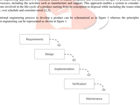
A conventional engineering process to develop a product can be schematized as in figure 1 whereas the principles of concurrent engineering can be represented as shown in figure 1.
IJEDR1603042
International Journal of Engineering Development and Research (www.ijedr.org)258
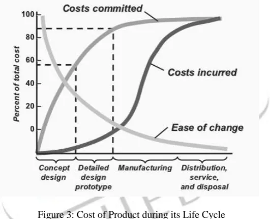
Figure 2: Conventional Engineering ApproachResearch activities related to application of concurrent engineering principles in manufacturing environments and which information is available in published literature confirm that they ensure enhanced variety and technical complexity of a product at compressed product never ending demands of consumers [3, 5]. In general, the cost of a product during its life-time can be schematically represented as shown in figure 3 [6].
Figure 3: Cost of Product during its Life Cycle It has been found from earlier works that Concurrent Engineering aids in [7, 8]
Development and Production Lead Times
Measurable Quality
Improvements Engineering Process Improvements
Cost Reduction
II.DESIGN AXIOMS AND ITS IMPORTANCE
They are the general truths which cannot be proven by any known methodologies or techniques. The following are some of them which are essentially followed while implementing concurrent engineering principles in product design and development process [9, 10].
Minimize the number of functional requirements and constraints
Satisfy the functional requirements from most important as first to least important as last
Minimize information content
Everything being equal, conserve materials
Integrate functional requirements in a single part if they can be independently satisfied in the proposed solution
IJEDR1603042
International Journal of Engineering Development and Research (www.ijedr.org)259
III.CASE STUDIES (PRODUCTION OF CYLINDRICAL PARTS)
Consider the case of production of cylindrical parts through turning operations by a company. Total number of parts required are 1000 and the tolerance has to be maintained at 1 ± 0.003 cm. This situation can be examined considering both conventional as well as concurrent engineering approaches.
Conventional Engineering:
Recommended dimensions of the product and its tolerance are 1±0.003 cm. Manufacturing engineering will challenge this specification only if the design is not producible. It is decided to produce the parts on a lathe since the desired tolerances can be achieved. The process average and the standard deviation are estimated to be 1.00 and 0.003 cm, respectively. Further,
Unit Cost of Raw Material = Rs. 10 Unit Salvage Value = Rs. 2 Unit Processing Cost = Rs. 7
Process Engineer determines the unit cost of output, number of units of scrap generated and number of raw units required to produce 1000 finished units as follows.
Unit Cost and Scrap Calculation:
Since lathe is the first choice option, j = 1.
Assuming tolerance as 1±0.003 cm, as the first design option, k=1. All parts apart from tolerance limits are scrapped.
For the given data it is Zu = 1.00 and 𝑍𝑙 = -1.00.
Therefore from the normal table, the percentage of items above and below the tolerance limit is 15.87% each resulting in total percentage of rejections at 31.74%.
Therefore,
Technological Co-efficient of Scrap, 𝑘11𝑠 = 𝑆𝐶11
1− 𝑆𝐶11 =
0.3174
1−0.3174 = 0.4649
Technological Co-efficient of Input, 𝑘11𝑖 = 1 + 𝑘11𝑠 = 1+ 0.4649 = 1.4649
Number of Units Scrapped, 𝑌11𝑠 = 𝑘11𝑠 * 𝑌11𝑜= 0.4649 * 1000 = 465 (Approx)
Number of Input Units Required, 𝑌11𝑖 = 𝑘11𝑠 * 𝑌11𝑜 = 1.4649 * 1000 = 1465 (units)
Unit Output Cost, 𝑋11𝑜 = 𝑘11𝑖 𝑋11𝑖 - 𝑘11𝑠 𝑋11𝑠 + 𝑘11𝑖 𝑓(𝑌11𝑖)
= 1.4649*10 – 0.4649*2 + 1.4649*7 = Rs 23.97
Concurrent Engineering:
Concurrent Engineering is based on cross- functional and multi-disciplinary teams representing various functional areas. Hence in this approach, marketing, design, manufacturing engineering and all stakeholders in the product development processes are brought together to discuss issues related to integration of functional design, manufacturing, quality control, customer service and so on. This multifunctional team is responsible for addressing various issues such as,
The marketing services of the company feels that the tolerance range of 1 ± 0.003 cm is too tight.
The quality department finds the number of rejections is too high.
The manufacturing and planning department wishes to use machine tools with better process capabilities.
IJEDR1603042
International Journal of Engineering Development and Research (www.ijedr.org)260
In a scenario such as this, concurrent engineering team conducts the first meeting whose outputs are as follows:Without compromising on shaft dimensions of 1 ±0 .003 cm, the manufacturing department recommends a CNC which has higher process capability as well as flexibility for different work operations resulting in a process standard deviation of 0.002 cm.
This leads to an increase in the processing cost at Rs 9.00 per unit from the previous cost of Rs. 7.00.
The output unit cost, number of scrap units generated and number of raw units required to produce 1000 finished units are determined as follows:
Since CNC is second manufacturing technological alternative, j = 2. Whereas k =1, since there is no change in the design specifications. 𝑍21𝑢 = 1.5, 𝑍21𝑙 = -1.5.
Percent rejection above the upper limit is 6.7, whereas that below the lower limit = 6.7, Total Percentage Rejection = 13.4% and 𝑘21𝑠 = 0.1547 and 𝑘21𝑖 = 1.1547
Therefore,
Number of Units Scrapped, 𝑌21𝑠 = 𝑘21𝑠 * 𝑌21𝑜= 0.1547 * 1000 = 155 (Approx)
Number of Raw Units Required 𝑌21𝑖 = 𝑘21𝑖 * 𝑌21𝑜 = 1.1547 * 1000 =1155 (Approx)
Unit Output Cost, 𝑋21𝑜 = 𝑘21𝑖 𝑋21𝑖 -𝑘21𝑠 𝑋21𝑠 +𝑘21𝑖 𝑓(𝑌21𝑖 ) = 1.1547*10 – 0.1547*2 + 1.1547*9
= Rs 21.63
Continuing the iterative meetings to consider the feedback from the marketing personnel, the design engineers decide to fix the tolerance limit at 1 ± 0.004 cm which is still capable of meeting the customer requirements while the unit output cost reduces to Rs 19.78.
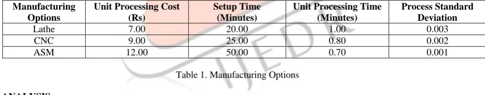
Further reduction in unit output cost can be attempted by exploring the possibility of employing ASM (Automatic Screw Machine) whose process capability is better than an ordinary lathe as well as that of CNC resulting in unit cost of output at Rs 12.00. The summary of iterative meetings can be mathematically summarized as in table 1.
Manufacturing Options
Unit Processing Cost (Rs)
Setup Time (Minutes)
Unit Processing Time (Minutes)
Process Standard Deviation
Lathe 7.00 20.00 1.00 0.003
CNC 9.00 25.00 0.80 0.002
ASM 12.00 50.00 0.70 0.001
Table 1. Manufacturing Options
IV.ANALYSIS
Conventional Engineering:
The number of rejections can be considered as measure of process quality. Estimation of manufacturing lead time is another important parameter.
If it takes one minute to manufacture one item on lathe, then Unit Cost = Rs 23.97
Set up Time = 20 min
Number of Rejections = 465
Manufacturing Lead Time = Set up Time + (Number of Units turned on Lathe * Time per Unit) = 20 + (1465*1.00)
IJEDR1603042
International Journal of Engineering Development and Research (www.ijedr.org)261
Concurrent Engineering:The time required to manufacture one item on an automatic screw machine is 0.7 min. Therefore,
Unit Cost = Rs 12.00
Set up Time = 50 min
Number of Rejections = 00
Manufacturing Lead Time = Set up Time + (Number of Units turned on ASM * Time per Unit) = 50 + (1000*0.70)
= 750 min
Improvement in Cost, Quality and Manufacturing Lead Time
The Improvements in Unit Cost, Quality and Manufacturing Lead Time by using concurrent engineering approach are as follows:
Percentage Improvement in Unit Cost = 23.97−12
12 x 100 = 49.93%
Improvement in Quality = Zero scrap compared with 465 units scrapped using a lathe. Percentage Improvement in Manufacturing Lead Time = 1485−750
750 x 100 = 98%
V.CONCLUSION
Examination of the typical case study and its analysis clearly reveals that the importance of concurrent engineering approach in the design and development of a product need not be over emphasized. Considerable reduction in the production cost and processing times and the enhanced quality in terms of reduced rejections during the production of cylindrical shafts employing different facilities option for manufacturing establishes the enhanced scope of the approach over others.
VI.ACKNOWLEDGEMENT
Authors wish to thank Atmiya Institute of Technology and Science for Diploma Studies, Rajkot, Gujarat, India to allow them to perform research on Concurrent Engineering in the college workshop itself.
VII.REFERENCES
[1] Ellram L.M., Tate, W.L., Carter C.R.“Product-Process- Supply Chain: An Integrative Approach to Three-Dimensional Concurrent Engineering”, International Journal of Physical Distribution & Logistics Management, v 37, N 4, 305-330. [2] Blackhurst J., Wu T., O’Grady P., “PCDM: A Decision Support Modeling Methodology for Supply Chain, Product and
Process Design Decisions”, Journal of Operations Management, v 23, 325-343
[3] Ellram L.M., Stanley L.L., “Integrating Strategic Cost Management with a 3DCE Environment: Strategies, Practices, and Benefits”, Journal of Purchasing & Supply Management, v 14, 180-191
[4] ElMaraghy H.A., Mahmoudi N., “Concurrent Design of Product Module Structure and Global Supply Chain Configurations”, International Journal of Computer Integrated Manufacturing, v 22, N 6, 483-493
[5] Lu S.C-Y., Elmaraghy W., Schuh G., Wilhelm R., “A Scientific Foundation of Collaborative Engineering”, CIRP Annals - Manufacturing Technology, v 56, Issue 2, 2007, 605-634
[6] Gokhan N.M. Needy K.L., Norman B.A., “Development of a Simultaneous Design for Supply Chain Process for the Optimization of the Product Design and Supply Chain Configuration Problem”, Engineering Management Journal, v 22, N 4, 20-30
[7] Krishnan V. & Ulrich K.T., “Product Development Decisions: A Review of the Literature”, Management Science, v. 47, N 1, 1-21
[8] Tomiyama T., Gu P., Jin Y., Lutters D., Kind Ch., Kimura F., “Design Methodologies: Industrial and Educational Applications”, CIRP Annals - Manufacturing Technology, v 58, Issue 2, 543-565
[9] Suh N.P., “Axiomatic Design Theory for Systems”, Research in Engineering Design, 10, 189-209