IJEDR1504089
International Journal of Engineering Development and Research (www.ijedr.org)540
Safety Featured Elevator Control Using PLC
Vishakha Sadhwani;Yash Sikkewal Students
Electronics And Telecommunication Engineering, Bhilai Institute Of Technology,Durg (CG)
________________________________________________________________________________________________________
Abstract— This work represents a design and implementation of a elevator using PLC. It is a demonstration and a prototype for a three level elevator system control that is used as a transport device to move goods or people .The main objective is to design and implement an elevator using DC motor. It can be used to fetch car and move up/down according to input given by the programmer. Such a device can be used in industry, hotels, shopping centers, office building and airport. This paper specifically deals with programmable logic controller (PLC) as the main controlling device to regulate all the activities of the elevator. In this we mainly focus with PLC ladder logic, thus this paper describes the application of PLC for elevator control system .This control system is described with the use of SO Machine V3.1 programmable logic controller to monitor and instruct a 3-floor elevator system. It can be displayed in any windows based computer system and operators can be warned when errors occur and correction must be performed. The program is executed in respond to the inputs entered. The input devices are sensors, limit switch and push buttons. The output devices are a control panel which gives a message when the lift is reached to the desired floor. Hooter, dc motor and led display are the other output devices.
Index Terms - PLC, ladder logic, sensors, limit switch, proximity sensor, SO Machine, V31 PLC, DC Geared motor ________________________________________________________________________________________________________
I. INTRODUCTION
An elevator is a transport medium used to move goods or people vertically, from one floor to another floor. The elevator turns electrical power into mechanical power. It is made of four components _ the lift cab, shaft, the drive system and the counterweight, and is moved vertically using pulley system.
The elevator must fit within the given space requirements of the industrial area/building. It must be large enough to deal with the normal life traffic & to move necessary objects within the building.
II. PLC
It works as a digital computer used for automation of industrial such as control of machinery equipments on factory assembly lines. Unlike general-purpose computers plc has multiple inputs & outputs. it has many advantages and known for flexibility,
low cost, speed, reliability, ease of programming , security and the ease with which errors are detected & corrected.
FIGURE 1 PLC is divided into three parts namely-
Central processing unit (CPU) Input/output selection
Programming device
The CPU functions by reading input data from various sensing devices, executes the stored user program from the program memory, and sends commands to control devices. The I/O system forms the interface by connected input output devices to the controller, the programming device stores the program, which determines the sequence of operation and ultimate control of equipment.
It is a collection of various electronic equipment and devices which are responsible for accuracy, stability, & implementation of process.PLC is the automated control system of which every component plays a crucial role.
1. INPUT DEVICES
The ability of PLC is nothing but its reading ability of input terminal; it reads i/p from various types of automatic sensing & manual i/p field devices.
The input devices are
Manual input devices: push button, keypad, toggle switches.
IJEDR1504089
International Journal of Engineering Development and Research (www.ijedr.org)541
2. OUTPUT DEVICESAn output system is incomplete without interface to the output devices. Some of the most commonly o/p devices are motor, solenoids, relay indicators & buzzer. It directly affects the system performance and is interfaced to PLC through wide range output module.
III. LADDER LOGIC
The ladder diagram has been widely used in the design of PLC. It is used for modeling sequential control systems. Here Petri net is used as a substitute of ladder system because ladder diagrams are used to model concurrent processes that are difficult to follow. An extended Petri net, the programmable logic controller net is defined which simplifies the structure of the Petri net by defining more complex semantics. Control system is constructed on the set of basic structures. The set of operation rules that implement the semantics of PLC net are in the rule base of simulation tool.. The simulation tool resides in a user-friendly graphical environment.
The main modeling method of the PLC is based on ladder logic diagrams (LLDs). However, as a system gets more complex. LLD implementation poses an obstacle in the design of more complex and real-time PLCs. So in this paper ladder logic processor is being introduced where each computation of the underlying ladder logic is perform at a fixed number of clock cycles per ladder rung, regardless of the number of steps involved. Thus this technique maintains the existing LLD paradigm where sequentially every rung is processed.
PLC Operation
The automation of many different processes, such as controlling machines or factory assembly lines, is done through the use of small computers called PLCs. This is actually a control device that consists of a programmable microprocessor, and programmed using a specialized computer language. A modern programmable logic controller is usually programmed in any one of several languages, ranging from ladder logic to Basic or C. Typically, the program is written in a developed environment on a computer, and then is downloaded onto the programmable logic controller directly through a cable connection. The program is stored in the programmable logic controller in memory.
Figure.2 operation flow diagram
IV. HARDWARE SECTION
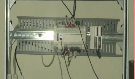
A PLC uses a backplane to serve as the communication bus for interconnecting the processor with input and output devices, with which it interacts.it receives input data for executing control program and transmit the control data for controlling the output targets. A PLC includes a rack into which input/output devices can be place. A rack includes several slots into which these input/output modules are installing. Each input/output card has a plurality of I/O points.
There are slots in which input output modules are pluggable in the backplane board in the plc and these input output modules are coupled with processor of the programmable logic controller via bus. The CPU itself is present in the backplane board. With a particular processor of PLC and particular choice of input output cards the configuration is called hardware configuration of PLC .The hardware configuration also has a particular addresses which the I/O cards employ, a variety of input and output (I/O) signals, including analog signals, are processed using addressable I/O modules communicatively coupled to a processor.
IJEDR1504089
International Journal of Engineering Development and Research (www.ijedr.org)542
A typical PLC system includes at least one option module that performs input/output (I/O) functions with a plurality of input/output points. The option modules are coupled through an interface bus that is backplane, to a main controller with a microprocessor performing user program. Option modules may also include a microprocessor and a memory with a separate user programs and data directed to a particular operation of the PLC system. During the execution of a stored control program, the PLC's read inputs from the calibrator and, per the logic of the control program, provide outputs to the indicator and corresponding O/P tag. PLC's commonly utilize analog current regulator outputs for signaling and/or control purposes. To facilitate the necessary communication, the PLCs and related monitoring stations is connected with help of Ethernet card. One monitoring station is connect with another monitoring station with help of Control net card.V. SOFTWARE SECTION:
The software required for the total working of PLC is SoMachine and Vijeo designer.
1. So Machine - So Machine is having four hardware control platforms. It contains logic controller, motion controller, HMI controller, drive controller and safety I/Os. It is the combination of 1 single Schneider electric software and 4 hardware control platforms. It provides one machine environment in which one single software, one download, one connection and transparency is included. It is a flexible machine control. SoMachine is a mixture of 6 standard languages in which Function Block Diagram (FBD), Sequential Functional Chart (SFC), Structured Text (ST), Instruction List (IL), Ladder (LD), Continous Function Chart (CFC) are present.
2. Vijeo designer - Vijeo Designer is a software application with which you can create operator panels and configure operating parameters for human machine interface (HMI) devices. All tools needed to design an HMI project are provided from the data acquisition to the creation and display of animated drawings.
VI. HARDWARE IMPLEMENTATION
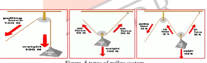
Figure. 4 hardware model Pulley system
There are many ways to lift an object by using the pulley system. But, each method used have their own advantage compare with others. There are three types of pulleys which is a fixed pulley, a movable pulley and a combined (compound) pulley.
Figure. 5 types of pulley system SENSORS
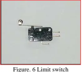
Level sensor was used for this project to detect the level arrived. This sensor also functioning as the system input to tell the programmable logic controller (PLC) about the current cab location. Here limit switch and proximity sensor is used as the sensor as shown in figure
LIMIT SWITCH
IJEDR1504089
International Journal of Engineering Development and Research (www.ijedr.org)543
Figure. 6 Limit switchPROXIMITY SENSOR
It acts as a sensors which is able to detect the metal surface by no-touch object detection. The most commonly used proximity sensors are the inductive type which generate an electromagnetic field to sense metal objects passing close to the face. In this project we uses NPN inductive proximity sensor of rating 24V.
Figure. 7 Proximity sensor SLIDING DOOR
There are a several components used for this part. The component used for real sliding door is not provided for prototype uses. Therefore the implementation for this part is simple and it operates like real sliding door operation. The components used are nylon rope, rack and pinion, holding
Figure. 8 Sliding door DC GEARED MOTOR
There are DC Geared Motor used in this project which is for lift up/down and open/close door. Even this two motor have same voltage capacity (12 volt), but it is different from the torque and load capacity. Another motor used in this project is Johnson motor.
Figure. 9 DC motor RELAY
Relays play an important role for most operation. It will determined the direction of DC Geared motor for both operation (up/down and open/close). Two relays were used in this one for required power supply and another for hooter. When relay one is turn on by the PLC according to instruction, it will change the polarity so that the motor will have potential different to make it running in one direction. This operation also the same when relay two was turning on by PLC in other situation to make it run in other direction. Single pole double throw types of relay were used for this project with relay voltage of 12 volt. This component is shown by figure below.
IJEDR1504089
International Journal of Engineering Development and Research (www.ijedr.org)544
Figure.10 RelayVII. HARDWARE RESULT
Even though this project result will be seen for the system operation, its operation generally just involved lift up down and open close door. The other operations like the priority of the calling button or user request cannot be seen by picture. It will limit our hardware result to show and can be represented by the basic operation of the elevator for the request to move up or down and to open or close the door.
For the lift up and down, the result can be observed that, when the cab has arrived at certain level, it will touch the sensor level (limit switch for this case). At this time the sensor will close the circuit and make a current to flow. The current will be feed to the PLC input as a input signal so that the processor will matching the information with instruction program to take the action. The PLC will execute the program after receiving the input signal and then sending the output signal to the motor. The cab will be moved upward or downward according to request from or to other level. The transition state operation is shown in figure 11.
figure.11 elevator system
VIII. PROGRAMMING RESULT
For the SoMachine programmer ladder diagram, the operation state is shown by the green highlighting colour. It can provide the monitoring operation without connecting the PLC with the system hardware to observe the operation. We can easily simulate the program by using the indicator output in Schneider electric PLC before connecting it to the system hardware.
RESULT
Up and Down operation
CASE 1: The cab at the base level. When there is a calling button from level two, the instruction will turn ON the motor up and make the cab going upward. When the cab reaches at level two and press the limit switch positioned at the top of the level two. T he PLC receive a signal and stop the motor.
Figure.12 Up Operation
In this instruction the cab will touch sensor at level one. The program will identify either there is request from this level. If there is no request from this level, the program will run for the next level to turn on motor up, MU to continue the operation.
When the cab touches the sensor at level two, the program will detect the request and turn off the motor. If the level is the same as requested by the user, the program will give the instruction to off the motor.
IJEDR1504089
International Journal of Engineering Development and Research (www.ijedr.org)545
Figure.13 Down OperationOpen and Close door operation CASE 1: Open door operation
When the cab arrive at any level and there is request for this level, we have to press a button for door open. CASE 2: Close door operation
After the opening of door, There is a timer, when the timer is off, the program will turn on motor to close the door after 10 second.Without the completion of complete door close,the movement of cab is not possible.
IX. CONCLUSION
The project contains both hardware and software for support the operation. Mainly the focus is given to build the system hardware and the software is used to program the Programmable Logic Controller, PLC to govern the operation for elevator. Besides, thi s programming also can be used to monitor the operation of the system as it is programmed. . The programming used for this project is Ladder Diagram provided by So Machine software for Schneider electric PLC. Therefore, the result will be taken for the hardware operation and the programming simulation.
REFERENCES
[1] Hesham Shaalan & control Res group, “teaching students about PLC” in Control Automation system,ICCAS 2008, International Conference on 14-17, pp: 1734 – 1737, October 2008
[2] Saurabh Sharma, T.Y.Ladakhi , A.P.Tiwary, Dr. B.B.Pradhan, R.Phipon, Application of PLC for Elevator Control System, International Symposium on Devices MEMS, Intelligent Systems & Communication (ISDMISC), Proceedings published by International Journal of Computer Applications® (IJCA),2011
[3] Romul COPINDEAN, Gheorghe TODORAN, Rodica HOLONEC, Dana FILIMON, The optimizing of two elevators control using the PLC, ECTA ELECTROTEHNICA
[4] Xinyun Yu1, Xiaoyun Feng1, and Chenglin Xiong , The Design and Implementation of Elevator Group Control System Research Platform, International Workshop on Information Security and Application (IWISA 2009), ISBN 978-952-5726-06-0, November 21-22, 2009
[5] Alvaro A. Patiño-Forero, Daniel M. Muñoz, Guilherme Caribé de Carvalho, Carlos H. Llanos, Modeling of an elevator group control system using programmable logic control and destination control system, COBEM 2009, 20th International Congress of Mechanical Engineering, ABCM November 15-20, 2009
[6] Macias, M.E. Guridi, E.D. Ortiz, A. ITESM, Monterrey, “about automation field”,Frontier Education, pp: S3G-18 - S3G-22, October 2007