R E V I E W
Open Access
Solving hidden terminal problem in
MU-MIMO WLANs with fairness and
throughput-aware precoding and a
degrees-of-freedom-based MAC design
Sanjeeb Shrestha
1*, Gengfa Fang
1, Eryk Dutkiewicz
2and Xiaojing Huang
3Abstract
We generally emphasize that the zeroforcing (ZF) technique backed by an appropriate medium access control (MAC) protocol can be used to address the inevitable hidden terminal (HT) problem in multi-user multiple input multiple output (MU-MIMO) wireless local area network (WLAN) settings. However, to address the implementation-specific requirements of MU-MIMO WLANs, such as fairness in client access and throughput of the network, we propose a fairness and a throughput-aware ZF precoding in our design at the physical layer (PHY). This precoding scheme not only solves the HT problem but also meets the fairness and the throughput requirements of MU-MIMO WLANs. Besides, we design a MAC layer protocol, supportive to PHY, which decides transmission opportunities (TXOPs) among access points (APs) based on the available degrees of freedom (DoF). We make a mandatory provision in our design that APs should have a sufficient DoF. This can ensure collision-free transmission whenever APs/transmitters transmit in the HT scenario. Additionally, we design an improved channel sounding process for MU-MIMO WLANs with a less signaling overhead than IEEE802.11ac.
We demonstrate the feasibility of our PHY in a USRP2/GNU Radio testbed prototype in the lab settings. It is found that our PHY improves the SNR and effective SNR of the received signal from about 5 to 11 dB in the HT scenario.
The performance of our MAC design is checked with simulation studies in a typical six-antenna AP and clients scenario. We observe that our MAC protocol has a slightly higher signaling overhead than traditional ready to send/clear to send (RTS/CTS) due to design constraints; however, the signaling time overheads are reduced by 98.67μs compared to IEEE802.11ac. Another interesting aspect to highlight is the constant Throughput gain of four to five times that of the traditional RTS/CTS. Our MAC protocol obtains this gain as early as 98.67μs compared to IEEE802.11ac.
Keywords: Hidden terminals, Precoding vector, Degrees of freedom, Transmission opportunity, Fairness, Network throughput
1 Introduction
Today wireless local area networks (WLANs) are very popular, and this trend is growing in an ubiquitous fash-ion. The penetration of WLANs is recorded as almost more than 70 % in household and business enterprises and about 30 % in public sectors such as transport, leisure, events, and streets, (http://www.infonetics.com/
*Correspondence: [email protected]
1Department of Engineering, Macquarie University, Balaclava Road, 2109 Sydney, Australia
Full list of author information is available at the end of the article
pr/2013/2Q13-Wireless-LAN-Market-Highlights.asp). Meanwhile, the growing use of multimedia services with heterogeneous hardware such as iPhones, laptops, HDTV, tablets, and the dependency of enterprises on WLANs for mission-critical networks have made WLANs dynamic in topologies, complex in irregular traffic patterns, and chal-lenging from an architectural view point. Measurements from production LANs [1] show that collisions of frames in WLANs are bound to happen, where transmission loss due to interference among 50 % of sender receiver pairs suffer a 2.5 % probability of transmission loss. While IEEE802.11 carrier sense multiple access/collision
avoidance (CSMA/CA) with ready to send/clear to send (RTS/CTS) has become a de-facto mechanism to avoid collisions, there exist inherent limitations as to how it treats interference at the receiver related to the carrier sensing at the transmitter. However, the fact is that successful transmissions mostly depend on an interference-free condition at the receiver. Theoretical and experimental work on CSMA/CA [2, 3] show that the CSMA/CA mechanism degrades performance due to poor spatial reuse. Besides, it also fails to address the hidden terminal (HT) problem [4] and capture effect [5] issues. Nonetheless, HT nodes (that do not sense each other’s transmission though they interfere with each other at the intended receiver causing decoding failure) are an inevitable phenomenon in WLANs and their impact on network throughput cannot be overlooked. The study in [6] reveals that HTs lead to about 40–42 % of collision loss.
In early years, a receiver-initiated busy-tone scheme was proposed to solve the HT problem for packet radio networks (PRN) and was found to be effective in elimi-nating collisions caused by HTs [4]. However, the scheme required a dedicated channel for the busy tone which is not desirable in wireless networks. Karn proposed the RTS/CTS mechanism as a part of MACA [7] to address the HT problem; however, experimental results show that RTS/CTS significantly reduces the overall throughput [8]. A recent study proposed a lightweight wireless hand-shake [9] where the header of the payload and ACK are separated and designed to act like RTS/CTS. Nonetheless, packet decoding in dynamic channels is a fundamental limitation for that approach. In addressing the HT in WLANs, adopting the solution used in CDMA is not viable as it requires tight power control and special codes [10], and at high SNRs, the performance is degraded. An alternative technique like zigzag decoding [11] analyzes collisions of packets with strategically selected collision patterns which show a significant packet reduction loss from 72.06 % to about 0.7 % in a test bed of 14 USPR nodes. Moreover, it needs to have a collision-free chunk to bootstrap decoding in an irregular traffic pattern such as in WLAN scenarios.
In the multi-antenna wireless network scenario, the physical layer (PHY) technique such as zeroforcing (ZF) has been used to design a medium access control (MAC) protocol [12, 13] and [14], where HT problem is briefly discussed. In [12], ZF beamforming technique for null steering similar to [13] was used in mesh networks. How-ever, it did not limit the channel bandwidth by splitting the channel into control and data sub-channels as in [13]. The flip side of the scheme was the inefficient use of the spectrum because after every successful commu-nication sessions, nodes were supposed to keep silent for a certain period of time specified in the field silent
period in RTS and CTS so that they might not disturb neighbors’ communications. Likewise, ZF beamforming technique enabling spatial reuse was presented in refer-ence to IEEE802.11s in [14]. However, the scheme relies on optional mesh coordinated channel access (MCCA) for channel access which is challenging from synchronization aspects in such a decentralized mesh network.
We present a fairness and a throughput-aware ZF pre-coding to deal with the HT problem in multi-user multiple input multiple output (MU-MIMO) WLANs. The PHY design is supported by a degrees of freedom (DoF)-based MAC protocol. Unlike its precursors that used ZF null steering approach for MAC design [12–14] and other HT solutions [4, 7, 9, 11], our design excels in twofolds. First, it maintains concurrent transmissions in the HT scenario (managed by our extended PCF). Second, it preserves fair-ness among access points (APs) (by the fairfair-ness algorithm) while deciding the transmission opportunities (TXOPs) for APs.
The authors have also published a MAC design to solve the HT problem based on ZF beamforming in [15]. There were two major focuses. First, it illustrates that ZF beam-forming is feasible for solving the HT problem in MU-MIMO WLANs. Second, it shows an outline of a MAC design which specifically introduced and discussed DoF-based TXOPs for APs, active and silent mode for APs and concurrent algorithm for clients’ selection. However, in this paper, we have worked out the finer details of our proposed solution for the HT problem and came up with interesting concepts both at PHY and medium access control (MAC) layer. Specifically, at the PHY, fairness in clients access along with the throughput of the network is given utmost importance. Thus, we proposed a fair-ness and throughput-aware ZF precoding to solve the HT problem. At the MAC, specifically, we refined the channel sounding process and clearly indicated the way to distin-guish between the desired and the undesired clients in the network. Additionally, medium access of APs and clients in both the downlink and the uplink, and the transition of our extended PCF to standard distributed coordinated function (DCF) and vice versa, are distilled on an event by event basis. DoF-based TXOPs and the concurrent algorithm are illustrated in detail.
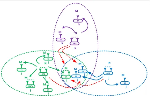
Fig. 1Hidden terminals. The figure illustrates the general hidden terminal problem in a MU-MIMO WLAN with the examples of theith,jth, andkth network AP2, AP1, and AP3 along with their clients in similar colors
clients (meaning that they do not belong to the same network, marked with different colors) suffer collision of signals from their respective hidden APs, i.e., AP1, AP2, and AP3.
From a high-level view, our proposed design makes the APs null their signals at the undesired clients (marked with different colors) while transmitting to the desired clients (marked with the same color) within their trans-mission range1. The aim is to ensure that, when the desired APs transmit to all the desired clients, there will not be any collision of signals. In such an approach, nei-ther of the APs has to listen and wait before transmission as is the case when using RTS/CTS, nor do the receiver clients have to re-encode any former decoded chunks as in the successive interference cancellation (SIC) scheme [16]. However, since APs lose as many DoFs as the number of antennas in which they cancel interfer-ence [17], this mainly brings two implications in the design. First, fairness issues among the desired clients and network throughput of an AP from the single-AP perspective. Second, TXOPs of the distributed APs in the HT scenario from the multiple APs’ per-spective. Both implications are discussed in detail in Section 3.
Our proposed design addresses these implications while solving the HT problem in MU-MIMO WLANs. The key contributions are as follows:
First, we propose a fairness and a throughput-aware ZF precoding at PHY to address the HT problem in MU-MIMO WLAN settings. For this, we specifically design a concurrent algorithm (described in detail in Section 4.1) based on both the packet queue position and the best quality of the channels between the APs and the desired clients at any instant (We refer this a concurrent algo-rithm based on first in first out (FIFO) + the Best of the Two Choices). Thus, our proposed design is able to main-tain both the fairness among the clients and the network throughput in MU-MIMO WLANs while solving the HT problem.
Third, the proposed solution basically converts the HT problem into the scenario where transmitters (APs in the downlink and clients in the uplink) can trans-mit concurrently without collision. Our MAC simulation studies show that the concurrent transmissions yield a network throughput of four times compared to the tra-ditional RTS/CTS scheme. This gain would otherwise be wasted with the RTS/CTS scheme where all nodes have to listen to the medium and wait for a random amount of time for transmission to avoid the collision of signals.
Fourth, we propose a modified channel sounding process for MU-MIMO WLANs in MAC, which has a reduced signaling time overhead of 98.67 μs than IEEE802.11ac’s signaling time overhead. APs in our design used this process to acquire channels from the desired and undesired clients within their transmission range.
Fifth, we tested the feasibility of our proposed PHY solution in a simple hardware platform consisting of URSP2/GNU Radio in lab settings. The results showed a notable received SNR gain from 5 to 11 dB compared to the HT scenario.
The rest of the paper is arranged as follows: Section 2 presents the HT-based system model in MU-MIMO WLANs. Section 3 presents a design overview. Section 4 illustrates the fairness and the throughput-aware pre-coding whereas Section 5 deals with our medium access control protocol. Section 6 describes our experimental setup. Performance evaluation is presented in Section 7, and a conclusion is presented in Section 8.
Notation:
The superscript (.)H denotes the Hermitian transpose whereas the operatorsE[.] and. denote the expecta-tion and the Euclidean norm, respectively. The matrices, vectors, and scalars are defined as they are used.
2 Hidden terminal-based system model in MU-MIMO WLANs
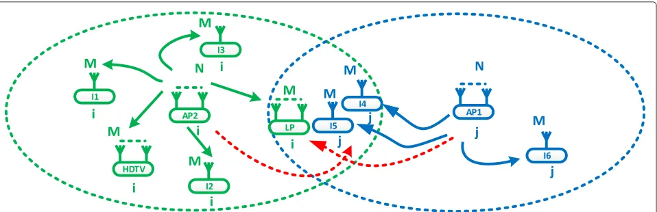
Consider a HT scenario as shown in Fig. 2 where theith network AP2 and the jth network AP1 are out of car-rier sensing range of each other, so they cannot hear each other’s transmissions. However, AP1 and AP2 can trans-mit to their clients, “I4,” “I5,” and “I6” and “I1,” “LP,” “I2,” “HDTV,” and “I3,” respectively, at the same time, causing collision of signals and decoding failure.
For simplicity and ease of discussion, we assume clients I1(1), I2(1), I3(1), I4(1), I5(1), and I6(1) have one antenna whereas clients LP(2) and HDTV(2) have two antennas. The corresponding antenna/s associated with the clients is/are shown in parentheses whenever necessary.
Suppose there areKaccess points (APs) who are out of carrier sensing range of each other and are transmitting simultaneously. Clearly, at one of thejth reference clients I4, we have collision of signals that are coming fromK−1
HT nodes. For simplicity and ease of discussion, we take thejth network AP1 and client I4 as a reference as shown in Fig. 1. We consider N transmitting antennas (differ-ent for each AP) at the APs and M receiving antennas (different for each client) at the clients.
The received signal at thejth network client I4 is now given by represented by w ∈ CM×1and is modeled as circularly symmetric additive white Gaussian noise with zero mean andσ2 variance. All the APs satisfy the transmit power constraintP, i.e.,Ex2i<P, fori∈ {1, ..,j−1,j,. . ..K− 1,K}. The concatenation of channels at thejth network client I4 is given by
H=hH1j,hH2j, . .. . .hHjj,. . . .hHK−1j,hHKj (2) whereHis a [M×KN] matrix with thejth row equal to the channel of theKAPs to thejth antenna element of the jth client withMantennas.
We assume that the interference level at each receiver/client in our system model is in the weak inter-ference regime, i.e., the interinter-ference is at 0<a=b a∗ where a and b are interference coefficients (if a two-interferer-based interference channel (IFC) is considered) anda∗is the critical value where there is a sudden change in the slope [18]. By this, we mean that, first, the receivers make no attempt to decode and subtract the received interference fromK −1 APs to get their desired signal. Second, the only way to get rid of collision of signals at the receivers in our system model is by preventing the inter-ferences reaching the receivers. The main justification for this assumption is that, in most envisioned MU-MIMO WLAN applications, clients would use receivers with a simple architecture. Additionally, in a dynamic environ-ment of WLANs, interference subtraction is difficult as the receivers do not know the coding and modulation schemes used by the interfering transmitters.
Our assumption is directly in contrast with the presence of a very strong interference, where Carleial [19] in 1975 showed the striking fact that very strong interference is as innocuous as no interference. The interfering signals are so strong in this case that the receivers may decode them reliably and subtract them from the received signal to obtain the desired signal.
3 Design overview
Fig. 2The hidden terminal problem with a specific two-network scenario, i.e.,K= 2. This is the hidden terminal-based system model in MU-MIMO WLANs that we have considered, with thejth network reference client “I4”. Here, we have takenK=2 APs, out of which AP1 is the desired AP for “I4” whereas the remainingith network AP2 is a hidden AP. GivenKhidden APs, there areKAPs interfering with the desired transmission at thejth network client “I4”
WLANs. The PHY design is supported by a MAC pro-tocol based on DoF, provided by the use of an excess service antennas both at APs and clients in MU-MIMO WLANs. Additionally, we present a modified channel sounding process with less signaling time overhead than IEEE802.11ac. Given uplink and downlink traffic, without loss of generality, we focus on downlink.
3.1 Precoding for MU-MIMO in our design
To place our design’s precoding algorithm in context, we begin with a brief introduction to conventional zeroforc-ing beamformzeroforc-ing (ZFBF) referenced to a multiuser MIMO interference channel (MU-MIMO-IC). Subsequently, we discuss the application-specific requirements of MU-MIMO WLANs. The aim is to highlight the need to adopt and enhance the classical ZFBF to effectively address the HT problem in MU-MIMO WLANs. Finally, we present an algorithm to precode APs’ transmissions in a HT sce-nario with twofold benefits: first, to cancel interference to undesired clients and remove collision of signals. Second, to maintain concurrent transmission to desired clients with optimal fairness and network throughput.
3.1.1 Premier-Zeroforcing beamforming in multiuser interference channel
ZFBF is a transmission strategy where the SNR of each desired stream is maximized subject to the constraint that interference to other clients is completely eliminated [20, 21].
Consider a MU-MIMO interference channel (IC) withK transmitters havingNantennas and their corresponding receivers, each with a single antenna as in a typical mul-tiple input single output (MISO) system. The interference to the undesired receivers is completely eliminated by ZFBF. Thus, the best ZF beamforming vector for anyith
transmitter is given by solving the following optimization problem fori∈ {1,. . . .K}
max
vi
log
1+h H iivi2
σ2 i
s.thHijvi 2
= 0∀j=i
vi2 Pi (3)
where hHijvi 2
= 0 is the ZF leakage constraint of the ith transmitter to the jth receiver. The optimiza-tion problem has a non-trivial soluoptimiza-tion given byvZFi = c ⊥[hi1,....hii−1,hii+1....hiK]hii, wherec is the scalar satis-fying the transmit power constraint. The necessary con-dition for the non-trivial solution is that the number of antennas at transmitterNis greater than and equal to the number of antennas at receiverM, i.e.,NM.
The signal-to-interference plus noise ratio (SINR) for thejth client in a network is given by
SINRj=
hHjjvj
2
σ2 j +
K−1 i=j
hHijvi
2. (4)
3.2 Design challenges
However, the solution is not so straightforward, as there are application-specific requirements in MU-MIMO WLANs (which are to be discussed shortly). The design challenge may be in the calculation of a precoding vec-tor which not only solves the HT problem but also meets the application-specific requirements of MU-MIMO WLANs.
Unlike cellular systems, MU-MIMO WLANs have heterogeneous antenna clients (it may be at home net-works or office network settings or elsewhere) such as iPhones, laptops, HDTVs. The numbers of antennas these clients possess are different. It may be due to space and cost constraints. For instance, iPhones have a sin-gle antenna whereas laptops and HDTVs can have two or more than two antennas. In the HT scenario, APs in MU-MIMO WLANs are entitled to serve heteroge-neous antenna clients with two contrasting objectives: (a) fairness in client access among (heterogeneous) desired clients and (b) maximize the network throughput. These specific objectives put a stringent requirement on the precoding vector while we address the HT problem in MU-MIMO WLANs. We shall shortly discuss the impli-cations of the specific objectives and our approach to the solution. Without loss of generality, we focus on downlink.
For instance, consider the previous MU-MIMO WLANs in Fig. 2. Specifically, whenever the six-antenna AP2 decides to transmit, it has to satisfy two conditions. First, remove interference to the undesired clients (I4 and I5) to get rid of the collision when AP1 transmits to them. Second, maintain concurrent transmission among the desired clients (I1, LP, I2, HDTV, and I3). It is worthwhile to note that in our design, both conditions have to be satisfied at the APs (focusing on downlink) at the same time by an appropriate precoding vector based on ZFBF.
For calculation of the precoding vector, APs have to consider the channel realization associated with the undesired clients, since interference cancellation is an important step in our design (the detailed pro-cess for acquiring channel state information (CSI) is given in Section 5.1). Having said that, it also becomes equally important for AP2 to consider who among the desired clients I1, LP,I2, HDTV, and I3 are served concurrently.
We highlight that the choice of the desired clients is vital in two respects. First, it is related to the concur-rent transmission among the desired clients, which in fact is associated with the AP’s network objectives such as maximizing the network throughput or maintaining fairness among the served clients and or both. We may consider this scenario as a popular load-balancing prob-lem among desired clients. Second, the choice of the desired clients forms an integral part in the precoding vector (detailed description is given in Section 4, Step 3,
and Subsection 4.1) which AP2 needs to calculate before transmission.
In summary, the design challenge for the HT problem in MU-MIMO WLANs with heterogeneous desired and undesired clients is to calculate a suitable precoding vector at the APs so that it can achieve the follow-ing simultaneously: (a) remove interference to undesired clients and avoid collision of signals and (b) maintain fair-ness and network throughput among the desired clients with concurrent transmissions.
Additionally, as there can be many APs involved in caus-ing the HT problem within a certain network in an area, another challenge is to design an appropriate decision-making scheme which can address the TXOP issue among APs.
We shall now discuss fairness and network through-put in concurrent transmissions and TXOP among APs in more detail.
3.2.1 Fairness and network throughput with concurrent transmissions
The ZF solution allows APs to transmit to their desired clients simultaneously/concurrently, while at the same time canceling interference to undesired clients in their transmission range in order to avoid collision of signals. We recall the fact that interference cancellation by APs to undesired clients with ZF costs precisely as many DoFs of APs as the number of antennas at the undesired clients. This means that APs with the remaining DoF have to oper-ate concurrent transmissions among the desired clients and at the same time cancel interference to the undesired clients.
For instance, consider the previous network at Fig. 2. Whenever AP2 is supposed to transmit, addressing the HT problem existing there by using our design costs AP2 exactly two DoFs to remove interference to the undesired clients (i.e., I4(1) and I5(1)). Recall that the number in parentheses indicates the number of antenna/s each client possesses. Thus, AP2 can have only four DoFs, by which it can at most serve four antennas concurrently while can-celing interference to the undesired clients at the same time.
the network throughput-aware ZF precoding is given in Section 4.
3.2.2 DoF-based transmission opportunity (TXOP) of APs/transmitters
Unlike the traditional time division-based medium-access mechanism in WLANs, our medium-access mechanism for ZFBF is based on both time and the remaining DoF of APs/transmitters. It is worthwhile to note that, instead of dealing with the total available DoF of the APs, we deal with the remaining DoF of the APs. The obvi-ous reason is that ZF precoding loses as many DoFs as the number of antennas where interference cancellation is done.
The traditional contention-based time division medium access for transmitters becomes inadequate for our fair-ness and throughput-aware ZF-based PHY design, as this would cause interference to undesired clients, if transmit-ters win contention at some instant but do not possess the required DoF for transmission. Thus, it becomes impera-tive to design a medium-access mechanism based on both time and the remaining DoF of transmitters. We aim to ensure that transmitters would have sufficient available DoF at the time they win contention for the medium and have TXOP.
The detailed discussion for TXOP among the transmit-ters is given in Section 5.2.
We shall now address the two design challenges, as dis-cussed above, from PHY and MAC perspectives. Network throughput and fairness with concurrent transmissions are illustrated from a PHY perspective whereas the TXOP of APs/transmitters is addressed in MAC.
4 Fairness and network throughput-aware precoding
The design objective of our PHY is to calculate a suitable precoding vector at APs which is not only fairness aware in terms of service access to clients but also supports max-imum throughput in the network. The PHY of our design obtains the precoding vector in the following steps:
•Step 1 APs go for channel sounding and measure the
CSI within their transmission range from both the desired, i.e., HiiQ =
clients. Thus, the total CSI isH=hii1,hii2,. . . ...,hiiQ,hij1,hij2,. . .hijP
where the number of desired clients and undesired clients, areQand P, respectively. A detailed description of channel sound-ing for the desired and the undesired clients, includsound-ing the ways to distinguish them, is given in Section 5.1.
•Step 2 APs know the number of antennas they possess,
i.e.,Nin our system model, and the number of antennas at undesired clients (i.e., PMin our system model) due to channel sounding in Step 1. Then, APs check whether
N >PMfor TXOP. Note that our MAC checksN >PM rather thanNPMat APs. The aim is to ensure that APs at least have 1 DoF after TXOP.
If the condition is satisfied, the APs win the TXOP and remain in an “active mode”; otherwise, they lose TXOPs at that instant and remains in a “silent mode”. The reason for remaining in the active mode and the silent mode is obvious. Those APs who have available DoF have the ability to remove interference to the unde-sired clients, so they will remain in the active mode and be ready for concurrent transmission in the next step. Otherwise, APs will remain in the silent mode because if they transmit with the lack of available DoF, they end up interfering with some undesired clients within their transmission range, causing collision of signals. More details about the modes of APs are discussed in Section 5.2.
•Step 3 Before the active mode APs go for concurrent
transmissions, they should know how many concurrent transmissions have to be made. APs calculate this by checking how many remaining DoF they have at that instant, i.e., (N − PM) > 0. The obvious reason is that we can at most have as many concurrent transmis-sions as the remaining DoFs that APs have in the active mode.
For instance, let (N − PM) = D, where D is the number of remaining DoFs of APs. Now, APs run the concurrency/scheduling algorithm and select D out of Q channel realizations keeping in mind the network throughput and fairness among the desired clients. For instance, HiiD =
hii1,hii2,. . . ...,hiiD
are the chan-nel realizations of the selected clients by the concur-rency algorithm where HiiD is a subset of HiiQ, i.e.,
HiiD ⊂ HiiQ, and the number of channel
realiza-tions are less than (if there are insufficient clients request an uplink) or equal to the remaining DoFs, i.e., HiiD ≤(N−PM).
The mechanism on howHiiD =
hii1,hii2,. . . ...,hiiD
is selected is part of the concurrency/scheduling algorithm, and detailed discussions are given in Section 4.1.
•Step 4 After HiiP and HiiD are determined in step 1
and step 3, the precoding vector is calculated. As for example, the precoding vector vi ∈ CN×1 for AP2 is
sizeN.U ∈ CDM×1is a unit vector acting as a demulti-plexer whereUHU=1. The conditionN≥PMhas to be satisfied in order to take the left inverse.2
The received signal at thejth reference client I4 of the jth network AP1 is given by
y=HHjjD
After winning the TXOP, the active mode APs decide which of the desired clients within the network are to be served concurrently, i.e., APs select D out of Q clients. APs in our design make this decision with the help of a concurrent algorithm which runs at APs.
It is imperative to note that the concurrent algorithm is an integral part of determining the precoding vector at PHY in our design, as described in Section 4, step 3. In this section, we illustrate how the concurrent algorithm is designed.
For instance, consider the previous network with AP2 with the remaining DoF equal to 4 and there are 5 desired clients namely, I1, LP, I2, HDTV, and I3, in the network to be served. Since AP2 in the network has only 4 remain-ing DoFs, it can at most serve four antennas concurrently. Now the critical question is how AP2 with TXOP chooses the clients among I1, LP, I2, HDTV, and I3 so that the objectives such as maximizing the network throughput or maintaining fairness among the served clients or/and both is/are met. We may view this scenario as a popular load-balancing problem among the desired clients.
For equal fairness among the clients within a net-work, desired clients can be served based on FIFO packet queues. As for example, suppose that the pack-ets are queued thus: I1(1), LP(2), I2(1), HDTV(2), and I3(1). Recall that the number in parentheses indicates the number of antenna/s each client possesses. In the FIFO algorithm, the first four packets in the queue are taken (because six-antenna AP2 has only 4 remaining DoFs while it has to null signals to two antennas of the unde-sired clients) and will be served first and the remainder will be served accordingly. However, AP2 will be unable to use 1 DoF in some FIFO queue patterns, for example, (a) I1(1), I2(1), I3(1), (b) I1(1), LP(2) and (c) HDTV(2), I1(1), where two or three consecutive FIFO clients already occupy 3 DoFs (out of 4 DoFs) of AP2 and is followed by a two-antenna client request, either LP(2) or HDTV(2). This is for the reason that the selection of two-antenna clients would exceed the remaining DoFs of APs at that instant.
Additionally, clients are chosen according to the packet queue request, irrespective of the channel quality. Thus, this method is highly oblivious to the network through-put, though it can ensure fairness in terms of FIFO request queues.
For maximizing the network throughput, one can choose the Brute-Force approach, where all the combina-tions among the desired clients, subject to the number of antennas being equal to the remaining DoFs of AP (i.e., 4 in the example) are checked and the best among the combinations that maximizes the throughput are chosen.
As in the case considered with clients queue: I1(1), LP(2), I2(1), HDTV(2), and I3(1), we simply use a
com-bination formula ([22], p17), i.e.,
3, respectively, resulting in 10 combinations3 of desired clients. Out of the ten possible combinations, 4, being unable to satisfy the constraint that the total number of antennas should be equal to the remaining DoFs of AP, are discarded. Thus there are six combinations among the five desired clients: I1(1), LP(2), I2(1), HDTV(2), and I3(1).
We choose the best combination among the six possible combinations for concurrent transmission that maxi-mize the throughput at that instant. Thus, the Brute-Force method will ensure a maximum throughput of the network. Nonetheless, it would undoubtedly end up with unfairness among the clients who cannot maximize throughput because they are not chosen for transmission. Also, this method can be very cumbersome for a large number of users, as the combinations grow because all the possible combinations of clients have to be checked.
In order to balance both the fairness and the throughput of the network, one possible solution would be the com-bination of the FIFO and the Best of the Two Choices. For fairness, we always select the first client in the queue for transmission. For the rest of the clients, we use the Best of the Two Choices. The Best of the Two Choices is one of the standard approaches for reducing the complexity of combinatorial problems [23].
For general illustrative purposes, we use the popular balls and bin model to show the superior performance of load balancing by the Best of the Two Choices [23]. Sup-pose that nballs are placed into n bins, with each ball being placed into a bin chosen independently and uni-formly at random. Let the load of a bin be the number of balls in that bin after all balls have been placed. It is well known that, with high probability, the maximum load upon completion will be approximatelyln(lnln(nn)). Thus, it is evident that the load is not balanced in the system.
maximum load drops to ln(ln 2ln(n)) + O(1) with high probability.
Thus, we pick the first client in the queue for transmis-sion to ensure fairness and the rest of the clients are cho-sen in accordance with a randomized design that exploits the Best of the Two Choices. In our considered scenarios of desired clients, I1, LP, I2, HDTV, and I3, this method results in four combinations out of all ten possible com-binations. Thus, we take the best combinations among the four which ensures the maximum network through-put. Hence, the FIFO combined with the Best of the Two Choices balances both fairness and network throughput.
Out of the three concurrent algorithms discussed above, based on fairness and network throughput, we use the FIFO combined with the Best of The Two Choices as a part of the concurrency algorithm in our design. This gives us D selected desired clients leading to HiiD =
hii1,hii2, ...,hiiD
as described in Section 4, step 3. The basic pseudo-code of the FIFO combined with the Best of the Two Choices is given as Algorithm 1. The simulation result of the concurrent algorithm is presented in Fig. 16.
It is imperative to note that the selection of the desired clients, i.e.,HiiD =
hii1,hii2, ...,hiiD
, with concurrency algorithm is an integral component for a fairness and net-work throughput-aware ZF precoding vector at APs as shown in the analytical expression in (5).
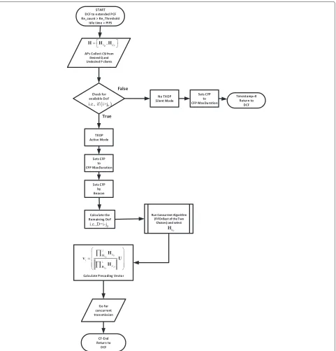
In a nutshell, a simple diagrammatic illustration of our design in PHY is given in Fig. 3. The fairness and network throughput-aware ZF precoding vector at APs satisfies the PHY objectives as described in Section 4.
5 Medium access control
Since the PHY solution of our protocol allows multiple APs to transmit concurrently to their desired clients with-out interference to undesired clients (alleviating the HT problem), we need to develop a MAC protocol suited for this.
Basically, the challenge for MAC is threefold. First, in order to get a suitable precoding vector as described in Section 4, the CSIs associated with both the desired and the undesired clients within the transmission range of the APs/transmitters have to be obtained. The
Algorithm 1Concurrent algorithm overview
1: procedure FIFOCOMBINED WITH THEBEST OF THETWOCHOICES
2: D←i−jP; APs calculate remaining DoF, whereiandjPare number of antennas at APs and the undesired clients at an instant.
3: APs then calculateHiDiD ∈ CDN×DMout ofHiiQ ∈CN×QMwhereHiiQ =
hii1,hii2, ...,hiiQ
by Concurrent Algo-rithm (i.e.,FIFO+Best of the Two Choices). SincePantennas of APs are used for interference cancellation, we are actually interested inHiDiD∈CDN×DM.
4: We use the following loop:
5: foriter1 to number of possible combinationsdo
6: offset=iter-1; for selecting different clients
7: forN1 toDdo;Nrepresents number of antennas in APs
8: forMd1 toDdo;Mdrepresents total number of antennas at desired clients 9: ifMd==1then
10: HiDiD(N,Md)=HiiQ(N,Md); always takes the first client in the queue.
11: else
12: HiDiD(N,Md)=HiiQ(N,Md+offset); for selecting the different clients.
13: end if 14: end for 15: end for 16: end for
17: For instance, given AP2,N = 6, with the desired clients’ queue ‘I1’(1), ‘LP’(2), ‘I2’(1), ‘HDTV’(2), ‘I3’(1) and the undesired clients ‘I4’(1) and ‘I5’(1),D=N−P=6−2=4.
18: Applying FIFO + Best of the Two Choices APs can have 4 possible combinations HiDiD ∈ CDN×DM=
‘I1’(1),‘LP’(2),‘I2’(1) or ‘I1’(1),‘LP’(2),‘I3’(1) or ‘I1’(1),‘HDTV’(2),‘I2’(1) or ‘I1’(1),‘HDTV’(2),‘I3’(1) (Note that for Fair-ness, the first client in the queue, ‘I1’(1), is always chosen irrespective of the channel quality).
19: APs check each 4 combinations with the standard MIMO capacity, i.e.,C=
D
i=1
log21+SNRN .λi
. The combination
Fig. 3Diagrammatic illustration of the design in PHY. The figure basically illustrates our design in PHY. It depicts the way to calculate fairness and throughput aware ZF precoding vector at AP
signaling/handshaking time overhead associated with this process must be as low as possible.
The detailed mechanism for a modified seamless chan-nel sounding process is given in Section 5.1.
Second, the mechanism for medium access for APs and clients is vital. Unlike traditional time-division-based decisions, APs/transmitters in our design decide TXOPs
based on the available DoFs of the APs. Thus, we need to design a mechanism that checks DoFs at APs and decides TXOPs accordingly. The provision for DoF-based TXOP for APs is presented in Subsection 3.2.2 whereas the decision procedure is presented in Section 5.2.
TXOP. We need to develop a mechanism at MAC to man-age these concurrent transmissions which has to compat-ible with the WLAN standard.
Other important aspects are to move the complexity of signal processing to the APs and dynamically change the combination of concurrent clients in bursty traffic demand, while respecting fairness. We shall discuss these aspects further.
5.1 Acquiring CSI associated with transmitter and clients While IEEE802.11ac incorporates MU-MIMO and pro-vides the basic framework for channel estimation with the null data packet in the standard (called channel sounding), it has noticeable signaling time overheads. We adopt and modify the channel sounding of IEEE802.11ac with a view to reduce a signaling time overhead and better utilization of the precious airtime of the APs. Keeping in mind that the channel sounding process should be as standard-compliant as possible for being amenable to commercial adaptation, we reused some data frames from the standard in our design. Addi-tionally, IEEE 802.11ac leaves the determination of the MU-MIMO precoding scheme open and implementation-dependent. We take ZF beamforming as the principal transmission strategy and design the sounding process accordingly.
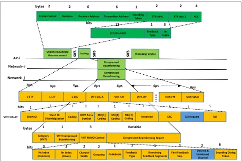
The channel sounding is initiated by those APs, who have packets in the queue for transmission. Since APs need to find the channels associated with desired and undesired clients for fairness and throughput-aware pre-coding, they first transmit a broadcast frame called “B_frame” so that the clients within the APs’ transmis-sion range can report their channels to the APs. The frame formats used in channel sounding are shown in Fig. 4.
Similar to the null data packet (NDP) announce-ment frame of 802.11ac, APs broadcast a control frame, B_frame, of 25 bytes. This frame contains a 6-byte field for the transmitter address (i.e., AP) and separate address fields for a set of multiple station information records used to request multi-user feedback. Most importantly, APs assign association identifications (AIDs) to the clients upon association which are included inside the 12 least significant bits (LSB) of station information (STA info).
The second step is to send the training symbols by APs for channel measurement. This is done by the training frame,T_frame, without a data field. Unlike NDP frames in 802.11ac, theT_frame in our design consists of 1-bit CSI request field at VHT-SIG-A2 in the VHT-SIG-A field. The tail bit consists of only 5 bits compared to 6 bits in 802.11ac. This change in tail bits is to make 24 bits corre-spond to one orthogonal frequency-division multiplexing (OFDM) symbol.
The function of the 1-bit CSI request field is to ask both desired and undesired clients their CSI within the
transmission range of APs. Unlike IEEE 802.11ac, it is worthwhile to note that there are no separate polling frames to acquire CSI from the undesired client. All the clients (desired and undesired) respond with their associ-ated CSI after the CSI request field is received as a part of the training frame.
The removal of the separate polling frame in our design in fact decreases the signaling time overheads in the chan-nel sounding process. Specifically, for the two-network scenario that we have considered in previous examples, it removes two short interframe space (SIFS) times and the time for one beamforming poll frame which equals 98.67 μs. The detailed calculation for signaling time overhead is presented in Subsection 7.2.1.
Each client analyzes the training symbols in the PLCP header (of the T_frame) and measures the channel between the APs and themselves. It is obvious that the clients within the overlapping region would hear multiple B_frame broadcasts. Each client responds to the channel request on a first in first out (FIFO) basis in the uplink.
After the reception of the T_frame, the third step is to feedback the measured channels. Owing to the lim-ited feedback channel, the channels (in the form of the matrices) are compressed and sent in the form of VHT compressed beamforming frames.
Since the APs need to differentiate the channels associ-ated with the desired and the undesired clients, our design uses 2 bits from the reserved bits of the compressed beam-forming action frame of 802.11ac. The 2 bits can have at most four logical combinations, which are used to distin-guish between the desired and the undesired clients. The reserved field bits are set “00” or “11” in the compressed beamforming action frame by the clients who have AID (i.e., desired clients). Otherwise, the bits are set “01” or “10” by the clients who do not have AID (i.e., undesired clients). Hence, upon the reception of the compressed beamforming action frame, APs check the reserved field and distinguish the CSI feedback between the desired and the undesired clients,HiiQandHiiP.
In terms of power, regulation can limit the transmit power based on the number of antennas used at the trans-mitter so that transmit beamforming does not increase the maximum distance range.
Figure 4 represents a basic diagram of the frame for-mats and the channel measurement process for the APs in a typicalith network, AP2 and two clients, each from the ith andjth networks.
5.2 Transmission opportunity for APs with heterogeneous antennas
Fig. 4Frame formats and basic channel sounding process. The figure shows the channel sounding process and the frame formats used for channel sounding. We present the channel sounding process considering theith network AP2 and clients from both theith and thejth networks
otherwise, the APs end up causing interference to other clients.
Before competing for TXOP, APs go for channel sound-ing and acquire CSI fromQdesired (i.e.,hiid) andP
unde-sired (i.e.,hiju) clients in their transmission range, where
id id=ju
∈ {1...QM} and ju ju=id
∈ {1...PM} as described
in Section 5.1. Second, APs make a decision for TXOP (i.e., choose to remain in the active or the silent mode), if i>ju
, for example for AP2, where i is the number of antennas at AP2, i ∈ {1...N}, and ju is the num-ber of antennas at undesired clients within range. Note that our design checks i > ju rather than i ju for TXOP. The aim is to ensure that every AP has at least one DoF after winning TXOP because interference can-cellation costs exactly as many DoFs as the number of antenna/s [17].
Suppose that we have three APs in a network havingN1, N2, andN3antennas, respectively. Each of these APs has I1,I2,I3antennas for undesired clients in the overlapping region. The three APs satisfyingN1>I2+I3,N2 >I1+ I3andN3 > I1+I2will have TXOP and will remain in the active mode; otherwise, the APs will not have TXOP
and remain in the silent mode at that instant. Hence, the TXOP among the APs are decided on the available DoF.
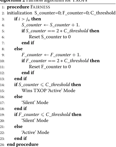
5.2.1 Fairness among APs with heterogeneous antennas Since TXOP for APs is based on DoF of APs, it is possible that APs with larger number of antennas (i.e., consisting of higher DoFs) would win TXOP all the time.
This may result in a deep unfairness among APs hav-ing fewer antennas. In order to prevent APs with a fewer antennas, starving for TXOP, our design executes a sim-ple fairness algorithm for TXOPs, which runs at APs. Since MU-MIMO WLANs are distributed in nature, the fairness algorithm for TXOPs is designed to ensure fair-ness among APs without requiring coordination with each other.
Algorithm 2Fairness algorithm for TXOPs 1: procedureFAIRNESS
2: initialization S_counter=0; F_counter=0; C_threshold 3: ifi>juthen
4: S_counter←S_counter+1.
5: ifS_counter==2∗C_thresholdthen
6: Reset S_counter to 0
7: end if 8: else
9: F_counter←F_counter+1.
10: ifF_counter==2∗C_thresholdthen
11: Reset F_counter to 0
12: end if
13: end if
14: ifS_counterC_thresholdthen
15: Wins TXOP ‘Active’ Mode
16: else
5.2.2 Fairness index of the algorithm for TXOPs
We evaluate the fairness index of our Algorithm 2 Fairness Algorithm for TXOPs, according to the Jain fairness index [24], which fundamentally gives a quantitative measure to any resource sharing or allocation problem. We con-sider three APs with two, three, and four antennas among which the fairness in throughput is studied. We assume that each AP, after winning TXOP, has at least one stream for transmission and has at most a number of transmis-sion streams equal to the number of antennas at the AP. For instance, a three-antenna AP has at least one trans-mission stream (worst case) and at most can have three transmission streams (best case) after TXOP. LetRibe the
ith AP that has TXOP andnbe the number of such APs; thus, the Jain fairness index is given by
f(R)=
Riis calculated as the ratio of the maximum throughput and the least expected throughput, i.e., for the AP with three antennas,
Ri=
Throughput when three streams are used Throughput when single stream is used . (8)
Similarly,Ri can be calculated for the remaining APs. The fairness index forn=3 (in our case) is calculated and is discussed further in Subsection 7.2.2.
5.3 Access to the medium
Since concurrent transmissions take place after the deter-mination of TXOP, there is no contention among the APs during concurrent transmissions. We exploit this funda-mental attribute of the concurrent transmission and adopt and expand the IEEE802.11 point coordination function (PCF) mode to address the concurrent transmissions. The reason is that concurrent transmissions are contention free and they can be governed by the contention-free period (CFP) of PCF (the detailed process is discussed below). Besides, the PCF is the part of the IEEE802.11 standard and its expansion to suit our PHY solution would be more straight forward to satisfy the interoperability issues.
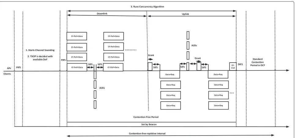
5.3.1 Contention-free period and contention period Similar to the PCF in IEEE802.11, we designate each AP in the network as a point coordinator. We divide time into CFP and contention period (CP) as shown in Fig. 5.
The beginning of the CFP is marked by the transmis-sion of a beacon by APs. This sets the duration of the current CFP. During CFP, APs run the concurrency algo-rithm as described in Section 4.1 and select the clients for transmissions both at downlink and uplink. The CFP is followed by CP, during which any clients can con-tend for the medium using IEEE802.11 and point-to-point MIMO. The objective of the CFP is to manage the con-current transmissions as much as possible so that the network throughput can be increased. The duration of CFP depends on the traffic congestion and may increase or decrease with the rise and fall of the traffic congestion. However, at CFP, the APs serve at least one packet (on downlink and uplink) to all clients that have pending traf-fic. In contrast, the duration of CP is constant. Similarly to IEEE802.11, we set the minimum length of CP to be equivalent to the time required to transmit and acknowl-edge one maximum-size frame. However, sometimes it is possible for the contention-based service to run past the expected beginning of CFP, which we call “foreshortening” of CFP.
5.3.2 Medium access to downlink
Fig. 5Extended point coordination function. We extend the traditional PCF for concurrent transmissions. Since concurrent transmissions are contention free, the CFP of PCF can be used for this purpose. The figure shows four concurrent transmissions as an example
traffic a group of clients selected by the concurrency algorithm.
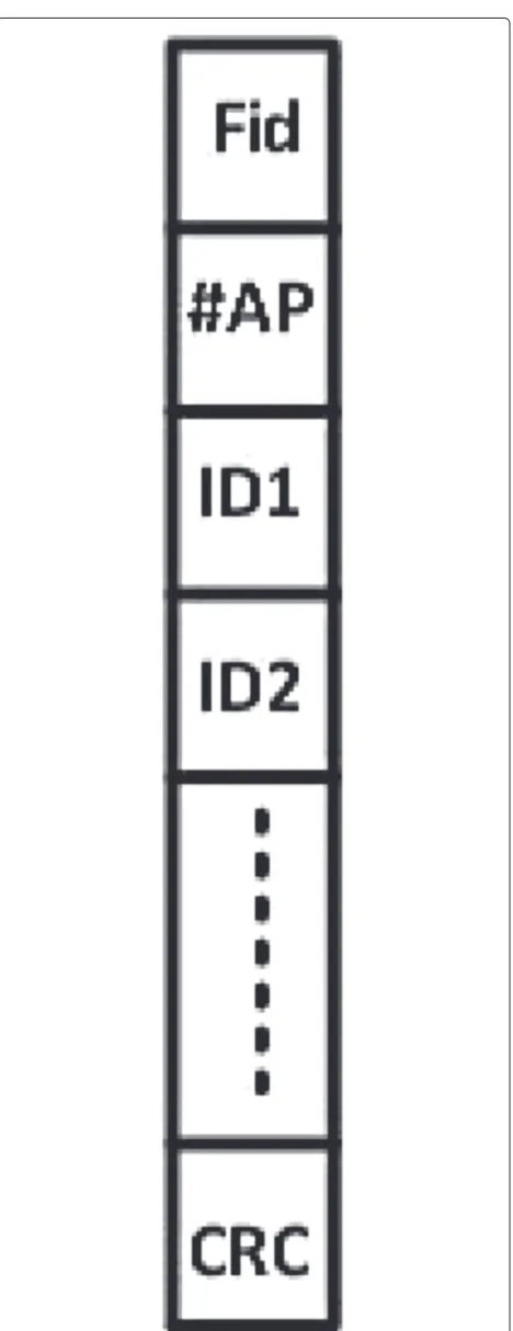
The CF-Poll+Data frame contains two parts. The first part of the frame is shown in Fig. 6 which contains IDs of the clients that are selected as the result of the con-currency algorithm. The IDs are given to the clients upon association to assist with control and management func-tion. It also contains the frame id, Fid, the address of APs, and the checksum of their broadcast. The APs and the clients use this checksum to test whether or not the received data is correct. The second part of the frame is the list of concurrent downlink data of the APs to the clients. For instance, a downlink transmission of the AP with four antennas is given in Fig. 5. Upon reception of data at clients in downlink, the clients send acknowledg-ments (ACKs) to AP. The order in which they send these ACKs is the same order as the IDs in the Data+Poll frame. Basically, clients send ACKs using the traditional MIMO. Thus, each received data at clients is acknowledged.
5.3.3 Medium access to uplink
The uplink data transmission at CFP is initiated by the grant frame5 broadcast by AP. The grant frame consists of the IDs of the clients determined by the concurrency algorithm that runs at APs. The clients in the uplink trans-mit the Data+Req frame. This frame contains the uplink data and, if there are more data in the clients to send, it also contains a request frame. The request frame is for transmission of the new frame in the uplink. How-ever, APs do not entertain the new requests immediately.
Instead, APs record the ids of the clients who have sent requests along with their uplink data and then polls them in the next cycle. Upon the reception of the poll request, clients with the new data can transmit to APs. APs decode Data+Req frame sent by clients by using the standard MIMO decoding method.
Upon the reception of the Data+Req frame, APs confirm the received data by the broadcast of the ACKs frames within its transmission range. The clients in the transmis-sion range receive the ACKs frames. However, the clients who are not selected for the uplink transmission discard the ACKs. Thus, clients are acknowledged for successful reception of data in the uplink transmission.
The end of CFP is marked by the CF-End frame broad-cast by APs. This frame indicates to the clients the end of the CFP. This frame prepares APs and clients to go back to the standard contention mode in DCF.
5.3.4 When to initiate the extended PCF?
Traditionally, the HTs are managed by the RTS/CTS mechanism. Basically, the RTS function determines whether the APs should use the CSMA/CA or the RTS/CTS mechanism to send the payload. Usually, the RTS threshold value is set in the range of 0–2347 and any data bytes more than the threshold exchange data by the RTS/CTS mechanism.
Fig. 6Metadata structure. This is the metadata that is transmitted with CF-Poll frames
retransmit the data and retry up to a certain count, Re_count. We compare Re_count and Re_Threshold and, if (Re_count>Re_Threshold), the extended PCF is ini-tiated. The provision of Re_Threshold is similar to the traditional RTS threshold value. However, we choose a retransmission threshold, Re_Threshold, for initiation of the extended PCF. This is because the presence of the HT scenario causes collisions of signals, and there is a high possibility of occurrence of retransmissions. In such a context, our proposed extended PCF comes into play to address the HT scenario.
5.3.5 It is worthwhile to note a few points • Are active and silent modes fixed?
The active and silent modes for APs are not fixed. Since the number of antennas that APs possess is
always fixed, so N is fixed. However, PM is not
fixed. It is variable and depends on two components:
first, the number of undesired clients, P, present in
any AP’s transmission range and second, the number
of heterogeneous antennas,M, each undesired client
possesses at the given instant where there exists the HT scenario.
Since PM vary from case to case, this will further
vary two components in our scheme. First the remain-ing DoFs at APs are variable because DoF=N-PM (this determines number of concurrent transmissions in the scheme). Second, the TXOP of APs varies because
TXOP = (N > PM). Thus, with variable PM, at one
instant, APs can satisfyN>PMand will have TXOP,
while at the other instant, APs may not satisfyN >
PMand lose TXOP. APs with TXOP will remain in
an active mode; otherwise, they will remain in a silent mode. Additionally, to ensure fairness for the APs who may remain in the silent mode for a long time and starve for TXOP, we have proposed Algorithm 2, a fairness algorithm for TXOPs.
• How the concurrent algorithm goes out of active and silent modes?
clients set their network allocation vector (NAV) to 32,768. On the other hand, silent mode APs do not transmit any Beacon frame; however, they constantly monitor the Timestamp and wake up at the elapse of CFP. Since the duration set for both the active and the silent mode APs is the same, the times when the silent mode APs wake up, and the transmission of CF-End, marking the end of CFP by the active mode APs, coincide.
• If there is no contention among the APs, how will they synchronize?
We see the need of synchronization in our scheme in two stages. Stage 1 synchronization is needed to invoke extended PCF when all APs in the vicinity start experiencing the HT problem. However, the chal-lenge comes from the decentralized and distributed nature of MU-MIMO WLANs where different APs do not communicate with each other. In such a con-text, we need a synchronization mechanism which can synchronize APs independently before we initi-ate extended PCF. We describe this synchronization mechanism in stage 1 which is achieved as follows: We use the Re_Threshold and the point control func-tion inter-frame spacing (PIFS) interval to synchronize APs before we initiate extended PCF. Since there exists the HT scenario among APs, there will be a collision of data packets and ACKs are not received at APs. This makes APs retry for transmission of data packets. Our scheme exploits this well-known process of APs in WLANs and set the same retransmission threshold, Re_Threshold, for all APs. Thus, whenever there is a HT problem in the network, APs in the vicinity reach their Re_Threshold more or less at the same time. Now, this is the time for APs to initiate an extended PCF.
Additionally, to better synchronize the initiation of the extended PCF, we make APs wait longer for a spec-ified PIFS interval. This process will give extra time to any APs who lag to reach Re_Threshold. Thus, all APs will be synchronized and will initiate an extended PCF at the same time.
Stage 2 synchronization is needed during the CFP operation. The synchronization is obtained via differ-ent types of frames used in CFP, such as managemdiffer-ent frames, control frames, and data frames.
For example, Acks in our scheme are synced as follows: (Acks) are sent after an SIFS interval when-ever APs or clients receive data packets in the uplink or downlink. Since the concurrent algorithm is used to select a group of clients who are to be served at an instant, the transmission of Acks after packet reception can be done by using the traditional MIMO technique both in uplink and downlink.
6 Experimental setup 6.1 The USRP2 platform
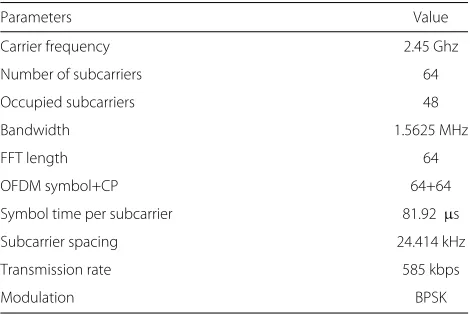
We implement our proposed PHY solution on the hardware platform made up of the Universal Soft-ware Radio Peripheral2 (USRP2) (http://www.ettus.com/). The RFX2400 daughterboards and Jacksion labs equip-ments are respectively used for the radiofrequency (RF) transmitters and receivers and for the clock to maintain synchronization. The standard GNU Radio libraries (http://www.gnu.org/) are used in the Ubuntu 11.04 envi-ronment. The experiment is carried out in the indoor environment with stationary nodes and with an oper-ating frequency of 2.45 GHz. Table 1 shows the PHY parameters.
6.2 Implementations
We construct the testbed with the help of four USRP2s equipped with RFX2400 daughterboards. We configure two USPR2s consisting of a single antenna each, to work as a single node6. These two antennas represent the ith network AP2 as in Fig. 2. The remainder of the USRP2s, consisting of a single antenna each, were configured as the jth network AP1 and thejth network client I4.
We then create the HT scenario by placing the jth network AP1 and the ith network AP2 equidis-tant from the jth network client I4. We use the same RF antenna (i.e., 50 mW) to ensure equal trans-mission powers at both APs. This condition is vital because the transmission would otherwise demon-strate the “capture effect” [5], where one transmission would capture the link and start transmission while the other terminal is affected by or may starve for transmission.
Additionally, the system requires a mechanism for chan-nel feedback in order to calculate a suitable precoding vector at the APs. We use time division duplexing (TDD) and achieve the CSI at the APs with the help of the preambles7. The packet preamble is augmented with each OFDM data symbol8, which consists of seven identical
Table 1Physical layer parameters
Parameters Value
Symbol time per subcarrier 81.92μs
Subcarrier spacing 24.414 kHz
Transmission rate 585 kbps
OFDM symbols each of length 64. Between the OFDM symbols, there are guard intervals of length 64. These form the cyclic prefix of our design9.
Nonetheless, due to USRP2/GNU Radio’s inability to support numerous instantaneous channels between APs and clients, we basically focus our prototype implementa-tion on interference cancellaimplementa-tion to the undesired clients so that, when the desired APs transmit to these clients, there will not be any collision of signals.
Specifically, first, the APs (AP1 and AP2) send the packet preambles. Second, the clients within the trans-mission range receive the preambles and update them to the host PC. The reception of the preamble is an impor-tant step as it contains crucial information such as OFDM symbol timing, carrier frequency offset (CFO), and chan-nel estimation. Third, the host PC calculates the chanchan-nel frequency response as shown in Fig. 7 and feeds them back to AP2 (In our prototype setting, we use the Uni-versity’s DHCP server for feeback purposes). After get-ting CSI at AP2, AP2 calculates the precoding vector for transmission.
The precoding vector is then multiplied by the transmit-ting symbols of AP2. As a result, interference is removed at the undesired clients I4(1). Hence, whenever the jth network AP1 transmits to itsjth desired client I4(1), at the same time withith network AP2, there will not be a collision of signals. The jth network client I4(1) is now able to detect the desired signal from the jth network AP1 and logs the results to the host PC. The host PC extracts the raw received signals with offline decoding using MATLAB®.
A general illustrative diagram describing the implemen-tation procedure is shown in Fig. 8. The abbreviations USRP2 sync and PV denote USRP2 synchronization and precoding vector, respectively.
6.3 Channel feedback
Timely channel feedback to the APs is vital, as stale CSI degrades the performance in terms of interference man-agement. To ensure timely CSI feedback, we first measure the feedback delay time (Tf) of our testbed environment (which is found to be 4.871 ms). Then, we compare it with the standard coherence time (CT), 21.2 ms, mea-sured by MacLeod et al. in [26] for ISM wireless indoor environments. Comparison shows thatTf is about a fifth of the standard CT. This ensures that the channel changes more infrequently than the feedback delay timeTf of our testbed environment, meaning that the precoding vec-tor is up to date with respect to changes in the channel conditions.
The comparison of Tf and the standard CT is made, as the measurement environment of the standard CT and our experimental environment is similar. Both are for the industrial, scientific, and medical (ISM) band and are inside a laboratory with electronic equipment, desks, tile floors, two walls at two sides, and two glassed walls.
7 Performance evaluation
7.1 PHY performance evaluation from the test-bed We consecutively do three things: First, measure the received SNR at thejth network client I4 under the HT
0 10 20 30 40 50 60 70
−0.4 −0.3 −0.2 −0.1 0 0.1 0.2 0.3 0.4
Subcarriers
Magnitude in dB
Fig. 8General implementation diagram. This is a basic diagram illustrating the process of implementation
scenario (i.e., both AP1 and AP2 are transmitting at the same time) shown in Fig. 2. Second, apply our scheme (i.e., both AP1 and AP2 are transmitting but theith AP2 uses the precoding vector to null the interference at thejth net-work client I4) and measure the received SNR at I4. Third, measure the received SNR at I4 with individual collision-free transmission (i.e., HTs collision-free transmissions when AP2 is not present).
We shall compare and analyze the raw received sig-nals, the SNR10, and the effective SNR (ESNR)11 in the aforementioned conditions.
7.1.1 Analysis from the raw received signal
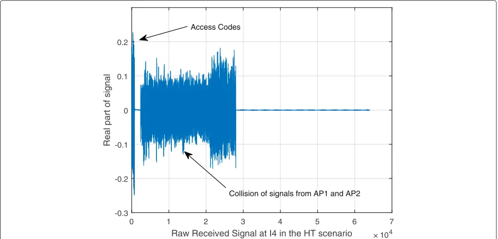
After the HT condition is satisfied, both AP1 and AP2 start transmitting. We observe that thejth network client I4 is totally flooded with the signals from both AP1 and AP2 (i.e., signals interfere with each other) as shown in Fig. 9. The observed y-axis shows a real part of the sig-nal. The signals lie within the range of−0.2 to+0.2 dB, however with some irregularities and spikes12.
We calculate and use the precoding vector at the ith network AP2 to null the interference at thejth network undesired client I4. This results in a raw received signal at
Raw Received Signal at I4 in the HT scenario × 104
0 1 2 3 4 5 6 7
Real part of signal
-0.3 -0.2 -0.1 0 0.1 0.2
Access Codes
Collision of signals from AP1 and AP2
thejth network client I4 from just itsjth network AP1 as shown in Fig. 10.
Also, we see the signal received from AP2. It is inten-tionally done to show what the AP2 signal would look like if it were not managed. It is the part of AP2’s signal where we deliberately did not apply interference cancellation.
7.1.2 The impact on the received SNR
We compare the received SNRs at thejth network client I4: (a) under the HT scenario, (b) with our proposed solu-tion, and (c) with the collision-free transmission. The SNR values for 48 occupied subcarriers of OFDM signals are plotted in Fig. 11.
We see a significant gain, in the received SNR (blue dots) of thejth network client I4 after applying our design, rela-tive to the SNR under the HT scenario (green dots). This improvement in SNR comes from the successivejth net-work AP1 transmission to its jth network client I4. The gain in SNR is significant because, in the HT scenario, the signal transmission is marred by interference from theith network AP2. However, after implementing our design, the interference is mitigated and yields a significant SNR gain.
In addition to this, there is an average of about 4– 5 dB difference in SNR between the received SNR of the collision-free transmission (red dots) and the received SNR with our design (blue dots) in Fig. 11. The SNR gain in a collision-free transmission is at the upper bound that our design is supposed to achieve.
Despite imperfections in interference mitigation caused by hardware offsets and other implementation limitations, our design possesses an acceptable received SNR gain of about 6 dB on average, with the 48 occupied subcarriers. This gain is about 10 dB in comparison to transmission in the HT scenario.
7.1.3 Analysis of ESNR
For multicarrier systems like OFDM, subcarriers may undergo different levels of fading, and these channel qual-ities cannot simply be represented by the overall received signal strength indication (RSSI)13due to frequency selec-tivity [27]. In such a context, the ESNR can be used as an important metric for performance evaluation. We use the availability of CSI at the subcarrier levels, as shown in Fig. 7, to measure the ESNR at thejth network client I4, by averaging the subcarriers’ bit error rate (BER) and then inverse mapping the BER to the SNR. From Fig. 12, we observe a rise in the ESNR value by about 10 dB for each modulation scheme after applying the PHY solution.
7.2 The MAC layer performance evaluation
We compare the signaling time overhead of our MAC with the traditional RTS/CTS mechanism in the con-text of the HT problem in WLANs. Also, we com-pare the signaling time overhead of our MAC and the IEEE802.11ac standard. We further compare the total network throughput gain of our MAC and the
Raw received samples at I4 × 104
0 1 2 3 4 5 6 7
Real part of signal
-0.3 -0.2 -0.1 0 0.1 0.2
Access Codes
Starts Interference cancellation
AP2's signal AP1's signal
0 10 20 30 40 50 −10
−5 0 5 10 15 20
Number of Subcarriers
SNR in dB
SNR−Collision Free SNR−Proposed Solution SNR−in HT
Fig. 11Comparison among the received SNR per subcarrier with collision freejth network AP1 and thejth network client I4 transmission, the proposed solution, and the HT scenario. We plot the received SNRs in collision-free transmissions, the proposed solution, and the HT scenario separately. We present them in one combined figure. The gain in SNRs is associated with 48 occupied subcarriers
traditional RTS/CTS. The throughput of our MAC and the IEEE802.11ac is also compared.
7.2.1 Signaling time overhead and capacity gain of MAC As shown in Fig. 4, the payload is not transmitted until we access all the channels and calculate the precoding vectors for the APs. This period is defined as the signaling period.
In a typical HT scenario for two networks, we calcu-late the signaling time overheads associated with different frames as shown in Fig. 4. Since a physical layer con-vergence protocol (PLCP) preamble and a PLCP header are added to an MPDU to create a PLCP protocol data unit (PPDU), the transmission duration of the broad-cast B_frame is given by TB_frame = PLCP frame +
-8 -6 -4 -2 0 2 4 6 8
BPSK QPSK QAM16 QAM64
SNR in dB
Types of Modulations
ESNR-ori ESNR-null