ABSTRACT
SO, JU-HEE. Controlling the Shape and Interfacial Properties of Eutectic Gallium Indium. (Under the direction of Michael David Dickey.)
This dissertation describes the fabrication and characterization of electronic and microfluidic
devices composed of a liquid metal alloy, eutectic gallium indium (EGaIn), utilizing its
rheological and electrical properties. EGaIn is a low viscosity liquid at room temperature
with metallic conductivity. The metal forms a surface oxide skin under ambient conditions.
This oxide skin allows the metal to maintain shapes that would normally be energetically
unfavorable due to surface tension. The chapters of this thesis describe new approaches to
study and utilize this skin to shape the metal, control its interfacial electronic properties, and
integrate the metal into new types of electronics that are soft or stretchable. We fabricated
and characterized fluidic dipole and patch antennas that consist of the liquid metal injected
into microfluidic channels comprising a silicone elastomer. The resonant frequency can be
tuned by reconfiguring the shape of the antenna mechanically without any hysteresis; the
antennas are therefore sensors of strain. We also present the fabrication and characterization
of highly stretchable and electrically conductive fibers. The fibers consist of the liquid metal
injected into stretchable hollow fibers composed of styrene ethylene-butylene styrene (SEBS)
resin. Mechanical measurements prove that the liquid core has negligible impact on the
mechanical properties of the fibers. The electrical measurements show the fibers maintain
metallic conductivity up to nearly 1000% strain, which may be useful for stretchable wires or
electronics integrated into clothing. We describe a new class of memristors composed
entirely of soft, liquid-based materials formed by combining the liquid metal and hydrogel
and the electrical resistance depends on its thickness, which can be controlled using electrical
bias and/or pH of the gel which interfaces with the liquid electrodes. The direction and the
magnitude of the electric bias pre-applied to the electrodes controls the anisotropy of current
conductance. The pre-programmed anisotropy is preserved for more than three hours, which
enables the fabrication of memory storage devices (i.e., memristors). The mechanical
stability of the liquid metal enables fabrication of microelectrodes for integrated microfluidic
devices. The metal can be injected into microfluidic channels in a single fabrication step to
produce structures that are self-aligned with adjacent microfluidic channels. The liquid metal
microelectrodes also span from the bottom to the top of the channel, and can thus generate an
effective electric field in micro-electro systems. We utilized a thin oxide skin of the liquid
metal to develop a new method to pattern the liquid into three dimensional free standing
microstructures in spite of the destabilizing effects of surface tension. Extruding the liquid
metal through a capillary or removing molds after injection of the metal into microchannels
produced free standing liquid microstructures. Lastly, we analyzed the rheological properties
of the liquid metal with the oxide skin in different chemical environments by using a
rheometer with a parallel plate geometry. The results suggest that certain environments
(water, acid) weaken the oxide corresponding with changes in the modulus and the yield
© Copyright 2012 by Ju-Hee So
Controlling the Shape and Interfacial Properties of Eutectic Gallium Indium
by Ju-Hee So
A dissertation submitted to the Graduate Faculty of North Carolina State University
in partial fulfillment of the requirements for the degree of
Doctor of Philosophy
Chemical Engineering
Raleigh, North Carolina
2012
APPROVED BY:
_____________________________ _____________________________ Michael D. Dickey Orlin D. Velev
Chair of Advisory Committee
DEDICATION
BIOGRAPHY
Ju-Hee So was born to Jongsik So and Sunhee Kim in Seoul, Korea and she grew up with her
older brother, Youngmin. After graduating from high school, she got her bachelor and master
degree in Chemical and Biomolecular Engineering at Seoul National University. After
working at Korea Institute of Science and Technology for one and half years, she decided to
pursue her doctoral degree at North Carolina State University in Raleigh, NC, USA. Under the
guidance of Michael D. Dickey, she pursued research on microfabrication, electronic and
ACKNOWLEDGEMENTS
First, I acknowledge my advisor Prof. Michael D. Dickey. I am thankful for all of the great
discussions, encouragement, advice and trust in me. I cannot dream of a better advisor. To
the Dickey research group members, thank you for your support throughout this epic journey,
I can only hope that I contributed as much to your careers as you did to mine. I would like to
thank Dr. Velev, Dr. Lazzi, Dr. Pourdeyhimi, Dr. Muth, Hyung-Jun, Rashed, Jacob, Gerry,
Amit, Sharvil, Shu and Collin for their hard work on the collaborated projects. Dr. Khan and
Dr. Parsons were generous enough to allow for me to use instruments in their lab. I really
appreciate their help. Thanks to Dr. Velev, Dr. Khan, Dr. Muth and Dr. Misra for serving as
my committee members. Thanks to the staff in the Chemical and Biomolecular Engineering
Department. You helped me navigate smoothly the road through the department.
I am deeply thankful for the time with my Korean friends at NC state university. It
has always been joyful and fun to get together with them and their support helped me to get
over hard times. I will remember the times we shared by traveling together, going picnics,
having parties, playing tennis and games, and having lunch with small talks.
I would like to acknowledge my parents and parents in law whose sacrifices,
teachings, and counsel made this achievement possible. Thank you for all you have done.
Thanks to my lovely daughter Minseo. Life with you has been amazing happiness and full of
unforgettable moments that will remain with me forever. My deepest gratitude is for my
husband Hyung-Jun. You have been my partner throughout this journey and your support and
TABLE OF CONTENTS
List of Tables ... viii
List of Figures ... ix
Chapter 1. Introduction ... 1
1.1 General Information on Low Melting Temperature Metals and their Applications ... 2
1.2 Properties of Eutectic Gallium Indium ... 13
1.3 Surface Oxide of Eutectic Gallium Indium ... 14
1.4 Eutectic Gallium Indium on the Micro-scale ... 17
1.5 Motivation and Layout of this Dissertation ... 20
1.6 References ... 24
Chapter 2. Reversibly Deformable and Mechanically Tunable Fluidic Antennas .... 30
2.1 Introduction ... 31
2.2 Background ... 32
2.3 Experimental Design ... 34
2.4 Fabrication and Characterization of Dipole Antennas ... 36
2.5 Fabrication and Characterization of Microstrip Patch Antennas ... 43
2.6 Advantages of Fluidic Antennas ... 46
2.7 Limitations ... 47
2.8 Conclusions ... 47
2.9 References ... 49
Chapter 3. Ultrastretchable Fibers with Metallic Conductivity Using a Liquid Metal Alloy Core ... 52
3.1 Introduction ... 53
3.2.3 Mechanical Characterization ... 56
3.2.4 Electrical Characterization ... 57
3.3 Results and Discussion ... 57
3.4 Conclusion ... 66
3.5 References ... 68
Chapter 4. Towards All-Soft Matter Circuits: Prototypes of Quasi-Liquid Devices with Memristor Characteristics ... 70
4.1 Introduction ... 71
4.2 Experimental ... 73
4.3 Fabrication and Characterization of Soft Matter Based Memristors ... 74
4.4 Conclusion ... 87
4.5 References ... 88
Chapter 5. Inherently Aligned Microfluidic Electrodes Composed of Liquid Metal ... 90
5.1 Introduction ... 91
5.2 Fabrication and Characterization of the Liquid Metal Microelectrodes ... 95
5.3 Advantages and Limitations ... 107
5.4 Conclusions ... 108
5.5 References ... 110
Chapter 6. Three-dimensional Printing of Free Standing Liquid Metal Microstructures ... 113
6.1 Introduction ... 114
6.2 Result and Discussion ... 118
6.3 Conclusion ... 125
Chapter 7. Tuning the Interfacial Rheological Properties of Eutectic Gallium
Indium ... 130
7.1 Introduction ... 131
7.2 Mathematical relationships ... 132
7.3 Experimental ... 134
7.4 Results and Discussion ... 136
7.5 Conclusion ... 139
7.6 References ... 141
Chapter 8. Summary and Outlook ... 143
8.1 Summary ... 144
LIST OF TABLES
LIST OF FIGURES
Figure 1.1 (a) Schematic illustration and photo of a self assembled monolayer junction between gold and mercury electrodes.[3] (b) Microfluidic split-ring resonator. Mercury flows into and out of a microchannel in the device.[4] (c) Surface tension driven microactuation of a mercury droplet based on continuous electrowetting.[5] ... 3 Figure 1.2 (a) Scanning electron microscopy (SEM) and optical microscopy images
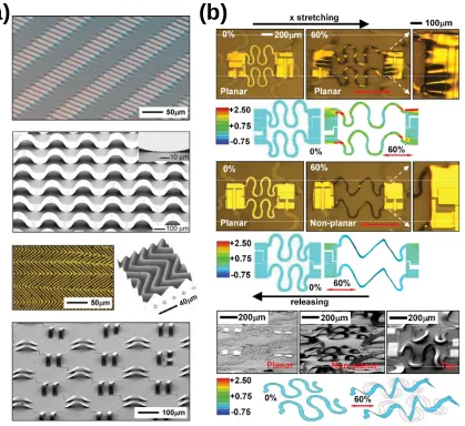
of inorganic structures on elastomeric substrates. The structures show different approaches to stretchable inorganic materials.[17] (b) Optical microscopy images and maximum strain distributions for serpentine interconnects composed of gold thin films.[17] ... 4
Figure 1.3 (a) SEM image of a gold network with microcracks at 20% strain. The applied strain is along the x-axis.[18] (b) The resistance of 50 nm thick gold stripe on a silicone elastomer increases with applied strain more than 3% and generates cracks perpendicular to the stretch direction.[19] .... 5 Figure 1.4 (a) Surface tension driven self-folding of patterned polyhedral. Two
dimensional templates fold when solder hinges between adjacent faces melts.[26] (b) Injection of liquid solder into microchannels produces deformable metallic structures.[21] ... 6 Figure 1.5 (a) Photographs of a stretchable loop antenna. The antenna is stretched,
folded, and twisted.[39] (b) The resonance frequency of a stretchable dipole antenna shifts as a function of applied strain. The mechanical deformation and the resulting frequency are reversible.[42] ... 9 Figure 1.6 (a) Photograph of a prototype of capacitive microfluidic device formed
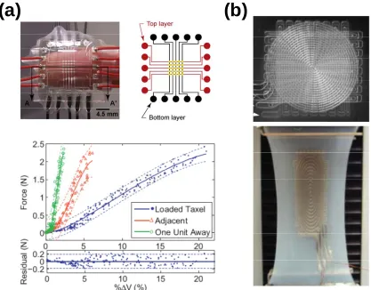
by embedding Galinstan within PDMS elastomer (top left), and a layout of microchannels (top right). Sensitivity of pixels to direct and indirect loading (bottom).[48] (b) Multilayered soft artificial skin sensor with embedded EGaIn microchannels.[46] ... 10 Figure 1.7 The electrically insulating oxide skin on the EGaIn electrode is reduced
bias oxidizes the liquid metal resulting in a resistive barrier for electrical current.[57] ... 12 Figure 1.8 (a) A series of side-view snapshots of EGaIn between the two parallel
plates of the rheometer. The plate rotated to the right of the center position (top), returned to its initial center position (middle), and the relaxed skin appeared crumpled after being stretched. The plate rotated to the left of the center position, and the creases of the skin slanted accordingly (bottom). (b) A plot of elastic and viscous modulus as a function of stress for EGaIn. The data shows that the EGaIn flows readily beyond a critical surface stress (0.5 N/m).[34] ... 16 Figure 1.9 (a) A series of photographs of the formation of a conical tip of EGaIn.
From left to right: A micromanipulator 1) brings a drop of EGaIn suspended from a needle into contact with a substrate, and 2) raises the needle until the EGaIn separates into a conical tip (which remains attached to the needle) and a drop on the substrate.[50] (b) Characterization of molecular rectification in Metal−SAM−Metal Oxide−Metal Junctions by using EGaIn soft top contacts.[51] ... 17 Figure 1.10 Pressure to fill EGaIn or Hg into microchannels increases as a function
of the inverse of the smallest width (1/W) of the channel.[34] ... 19 Figure 1.11 (a) (A, C) EGaIn droplets imaged by scanning electron microscopy
(SEM) and (B, D) transmission electron microscopy (TEM). EGaIn dispersed in (A and B) 3-mercapto-N-propionamide (1ATC9), and (C and D) 1-dodecanethiol (C12).[89] (b) EGaIn droplet formation in aqueous PEG solution using a microfluidic device. A series of images shows droplet generation at different flow rate ratios.[90] ... 20 Figure 2.1 (a) Fabrication process of a reversibly deformable dipole antenna.
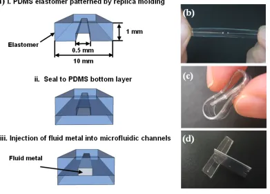
PDMS elastomer cured on a topographically-patterned substrate produces two adjacent microfluidic channels (only one shown). After sealing the PDMS channels to another piece of PDMS, injection of liquid metal alloy into the microfluidic channels produces a dipole antenna. (b-c) Photographs of a prototype antenna being stretched and rolled. There is no hysteresis in the spectral properties of the antenna as it is returned to the “relaxed” state. (d) The antenna self-heals in response to sharp cuts, such as those inflicted by a razor blade. ... 38
Figure 2.3. Photographs of the device used to stretch the fluidic antenna. (a) Two clamps with four screws secure each end of the antenna and slide parallel to the long axis of the antenna. (b) The dipole fluidic antenna mounted in the device. Two main screws exerted the required force to push the clamps away from each other; this motion caused the antenna to elongate in a controlled manner. ... 40
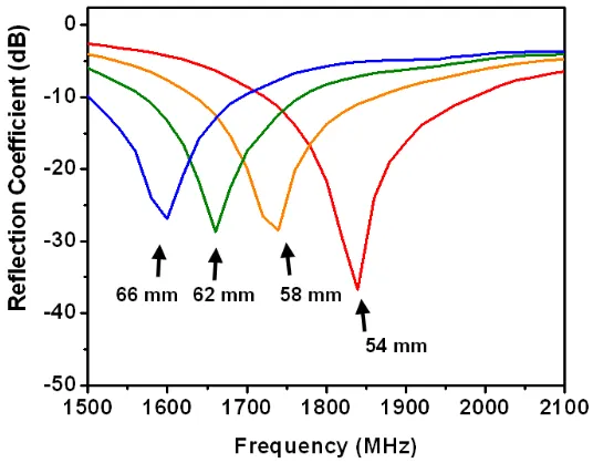
Figure 2.4 A plot of the measured reflection coefficient of the dipole both in its “relaxed” position (54 mm length) and mechanically elongated positions (58, 62, and 66 mm length) as a function of frequency. The ability to stretch the antenna allows the frequency to be tuned mechanically. ... 42
Figure 2.5 Resonant frequency of a fluidic dipole antenna as a function of the length of the antenna as modulated by stretching. The calculated values were modeled using finite element modeling. ... 43
Figure 2.6 Photograph of a partially filled patch antenna taken as the liquid metal fills the antenna in a serpentine fashion to ensure uniform and complete filling of the patch geometry. (right) A close-up micrograph of the leading edge of the liquid. ... 45
Figure 2.7 Photograph of a complete, evenly filled patch antenna and ground plane. (left) A close-up micrograph of a representative region of the radiating element shows the PDMS posts and the evenly filled liquid metal. ... 45
Figure 3.1 (a) Optical image of the cross-section of a hollow fiber. (b) The inner diameter (ID) and wall thickness (WT) of the fibers decrease with spinning rate. ... 58
Figure 3.2 (a) A relaxed, 2 cm section of an ultra-stretchable conductive fiber. The shiny core of its cross-section (inset) is the liquid metal. (b) The fiber is stretched to 20 cm and the metal appears to uniformly fill the stretched fiber ... 59
Figure 3.3 The strain-stress plots of elastomeric hollow (hollow symbols) and filled (solid lines) fibers with two different spinning rates. The fibers have the same mechanical properties with and without the metal. ... 60
Figure 3.4 Cycling test on the mechanical properties of the hollow fibers fabricated with a spinning rate of 1000 m/min. Beyond the first cycle (largest stress), the fibers show minimal signs of mechanical hysteresis. ... 61
spinning rates of (a) 100 and (b) 1000 m/min. The resistance increases as the applied strain increases. ... 64
Figure 3.6 (a) Stretchable charger for electronic devices and (b) stretchable cable for earphones. ... 66
Figure 4.1 Fabrication process of the memristive circuit with a crossbar structure. Two PDMS sheets with four circular holes of diameter ~ 2 mm were prepared to support hydrogel pellets doped with PAA (blue) or PEI (red). Another set of two PDMS sheets with line patterns were prepared by soft lithography (i.e., replica molding). Each PDMS sheet with holes was assembled with the PDMS sheet with line patterns and sealed by using oxygen plasma. After inserting the gel pellets into the holes, the two sets of PDMS sheets were aligned perpendicularly to create four nodes with gel-gel interface. The liquid metal was injected into the line channels by using a syringe and tubes to from electrodes at the top and bottom of the stacked gel layers. ... 74
Figure 4.2 Soft memristor prototypes based entirely on soft materials. (a) A schematic depiction of the memristive device. Two polyelectrolytes entrapped in a matrix of agarose/H2O dictate the pH values of each hydrogel layer. (b) I-V curves of the device by ± 5 V sweeps. The numbers and the arrows represent the order and the direction of the bias sweeps, respectively. The hysteresis of the I-V curves is the characteristic feature of memristors. The red dotted line indicates the reading bias of 1 V, where the “memorized” resistance is measured. The sweep rate is 0.04 V/s. ... 76
stays conductive, the formation and dissolution of an oxide layer at the PAA/EGaIn interface determines the resistance of the memristor. ... 78
Figure 4.4 The effect of pH conditions on the formation of oxide skin on the EGaIn electrodes. (a) Optical images of the surface of the EGaIn electrodes to which the voltage is applied in PAA or PEI polyelectrolyte solution of the same concentration as the memristor device. (b) The EGaIn electrodes in aqueous solution with identical pH values as the memristor device show the same surface morphological changes in terms of the bias application, which suggests that the different pH values of PAA and PEI polyelectrolyte solutions result in the difference in the oxide formation. ... 79
Figure 4.5 (a) Symmetric I-V traces with no hysteresis occur when electrochemically inert metals, such as platinum, were used as electrodes. (b) The device with Al electrodes shows slight I-V hysteresis because Al also forms an oxide layer on its surface. Compared to solid Al metal, it appears that the liquid EGaIn metal has the advantage of self-regeneration due to its fluidity, which results in reproducible hysteresis and more reliable memristive performance. ... 80
Figure 4.6 The device with symmetric PAA polyelectrolyte gel exhibited hysteretic I-V curves initially. However, since the oxide skin grows at both electrodes under the pH environment of PAA, total resistance of the device continuously increases as the bias loop is repeated. ... 81
Figure 4.7 Slight hysteresis occurs in the device with only PEI polyelectrolyte gel, which is maintained even in the consecutive bias cycles (left). However, the off-state resets spontaneously to the on-state after ~10 min because the oxide skin is unstable and removed under the PEI environment (right). ... 82
Figure 4.8 Performance characteristics of the gel/liquid metal memristors. (a) Conductance through the device depends on the pre-applied bias history. The current is suppressed (off state) below the maximum pre-applied voltage. (b) Switching performance of the memristors. (c) Long-term stability of the stored information. The low-conductance, i. e. ‘off’ state, is restored to ‘on’ state after 3 hrs by applying the switching bias. A switching bias of ± 5 V was applied to the memristors for 3 sec for the experiments of b and c. ... 83
longer switching times. Regardless, switching occurs after only 1 s of applying the switching bias. ... 85
Figure 4.10 A crossbar array of soft material-based memristors. (a) Photograph of a prototype of an integrated memristor circuit with a 2 × 2 crossbar array. The device is flexible as shown in the inset image and compatible with water. (b) Schematic of the prototype in (a). The arrows point to the nodes. (c) Switching performance of the memristor circuit device. The switching bias to turn ‘off’ (+ 5 V) and ‘on’ ( 5 V) the nodes is applied to the 1-B node for the first and second cycles and to the 2-A node for the third cycle, respectively, as shown by the arrows. The filled symbols represent the nodes in the ‘off’ state. The switching bias was applied to each node for 1 sec to minimize the crosstalk. ... 86
Figure 5.1 (a) Cut-away depiction of the process used to fabricate liquid metal microelectrodes in contact with a central fluidic channel. Two parallel rows of posts separate the liquid metal electrodes from the fluidic channel. (Not shown: The channels are sealed on top by a flat slab of PDMS.) (b) Top-down, back-lit optical micrograph of the fluidic channel flanked by two liquid metal electrodes. The posts prevent the metal from entering the fluidic channel. ... 96
Figure 5.2 Optical micrograph of microfluidic electrodes. (a) Electrodes flush with the central fluidic channel fabricated by injection. (b) Electrodes recessed from the channel. ... 98
Figure 5.3 Optical micrographs of the EGaIn (a) and Ga (b) electrodes after applying 2 V DC bias for 10 sec. Ga electrodes are stable in the solid state while one EGaIn electrode deforms as its thin oxide layer is reduced. ... 102
Figure 5.4 Optical micrographs of EGaIn electrodes under AC sinusoidal electric bias at 2V with two different frequencies 10 kHz (a) and 0.1 kHz (b). The dotted lines in (b) represent the location of PDMS posts and where the metal interface placed before applying bias. The EGaIn electrodes show improved mechanical stability as (c) the AC frequency increases at constant ionic concentration (0.1 M NaCl) and (d) the ionic concentration decreases at constant electric bias (10 V). ... 104
discoloration in these images) (b) The two fluids mix rapidly when 100 V DC bias is applied. ... 106
Figure 6.1. A series of sequential images in which a syringe needle extrudes liquid metal to form a straight wire on a withdrawn substrate (from left to right). The oxide skin on the surface of the metal stabilizes the liquid metal wire against gravity. The outer diameter of the hollow needle and the extruded wire is 500 and 270 m, respectively. The length of the final wire shown is 8 mm before it was intentionally ended by applying vacuum to the syringe. ... 119
Figure 6.2. Photographs of the diverse free standing, liquid metal microstructures. (a) Liquid metal spouted rapidly from a glass capillary forms a thin wire. (b) Suspended liquid metal fibers formed by rapidly extruding the metal from a syringe. The fiber is strong enough to suspend over a gap. (c) A free standing liquid metal arch structure spanning ~3 mm. (d) Tower, (e) 3 × 3 × 3 cube array and (f) crossover lines composed of liquid metal droplets. The droplets act as building blocks and form continuous physical and electrical junctions. (g) An array of in-plane lines of free standing liquid metal fabricated by filling a microchannel with the metal and removing the mold. Scale bars represent 500 m. ... 121 Figure 6.3. Observed (dot) and fitted (line) tensile force as a function of the
minimum circumference of the extruded wire. The slope of the graph represents the stress required to yield the surface oxide skin during the extrusion process, which is ~ 0.77 N/m ... 123
Figure 6.4. (a) A prototype device composed of two LEDs and stretchable wire bonds connecting them in PDMS (Inset: Micrograph of the liquid metal wire bonds). (b-d) The fluidic property of the metal wire in the elastomer allows stretchability (b) and flexibility (c, d) of the device and keeps its electrical continuity. ... 124
Figure 7.2 Oscillatory stress sweep of EGaIn in air, water and after drying. All the reported values are for surface modulus. The elastic modulus plateaus before the liquid metal yields beyond a critical stress. The elastic modulus decreases by an order of magnitude in water. The yield stress is also reduced by approximately a factor of three. The elastic modulus and yield stress of the dried metal is higher than the elastic modulus of the metal in water. ... 137
This dissertation describes the study of a micro-moldable liquid metal, eutectic gallium
indium (EGaIn) for the fabrication of soft and stretchable electronics with new functionality
and for novel approaches to pattern metallic microcomponents. Although much is known
about the metal, our studies focus on the composite system of the metal surrounded by an
oxide skin. Thus, the unique contribution of this thesis is new insights into controlling the
interfacial and electronic properties of the metal. In this chapter, we provide a general
overview on previous research on EGaIn as well as other low melting temperature liquid
metals and their applications. EGaIn has a thin solid oxide on its surface and the oxide skin
dictates electrical and rheological properties of the liquid metal. We discuss the properties of
the oxide skin and resulting unique behaviors of the liquid metal on the microscale. This
background information motivates the work described in this dissertation.
1.1 General Information on Low Melting Temperature Metals and their Applications Low melting temperature metals and alloys hold great promise for forming soft and
conformal metallic contacts, electro-microfluidic components, and highly deformable
electronics. The ability for liquid metals to flow also offers a new fabrication paradigm (e.g.,
injection) for metallic components and new opportunities for shape reconfigurable
electronics.
Mercury is one of the most well-known liquid metals and it has a number of uses. For
example, mercury dropping electrodes benefit from the fluidic properties of the liquid metal.
Pumping the liquid metal from a capillary maintains a pristine and clean electrode surface,
detection of trace-metals and organics in solutions.[1, 2] Mercury also has been used as a top electrode to measure electrical properties of molecular junctions such as self assembled
monolayers (SAMs) between two metal electrodes as shown in Figure 1.1(a).[3] The mercury
electrode supporting thin molecular layers is compliant and provides conformal contact to the
topography of a solid surface. This ability minimizes the potential of shorting and of
mechanical damage to the organic molecular layers. The fluidic properties such as low
viscosity also allow new applications of the metal in electronics and microfluidics (Figure
1.1(b) and (c)).[4-6] However, mercury has high surface energy and tends to minimize the
surface area which makes it difficult to control the shape and the fluidic behavior. Moreover,
mercury is toxic,[7-10] thus its use is widely eschewed.
J. Am. Chem. Soc., Vol. 123, No. 21, 2001
(a)
(b)
(c)
(a)
(b)
Figure 1.2 (a) Scanning electron microscopy (SEM) and optical microscopy images of inorganic structures on elastomeric substrates. The structures show different approaches to stretchable inorganic materials.[17] (b) Optical microscopy images and maximum strain distributions for serpentine interconnects composed of gold thin films.[17]
Recently, the emerging field of flexible electronics triggered more need and interest
in liquid metals to replace solid metals (e.g. copper), which have limitations with respect to
the type and amount of mechanical deformation they can endure. The flexibility of solid
intrinsic properties).[11-16] Figure 1.2 shows the different approaches that can offer stretchability and compressibility in brittle materials and how strain is distributed in the solid
structures.[17] Although thin films of solid metals are flexible, they show limited stretchability
and durability with repeated deformation (Figure 1.3).[18-20] In contrast to solid metals, liquid metals flow in response to applied stress and are therefore highly deformable and durable
without generating cracks or fatigue. Here, we discuss new functionalities and capabilities of
low melting temperature metals other than mercury.
(a)
(b)
Figure 1.3 (a) SEM image of a gold network with microcracks at 20% strain. The applied strain is along the x-axis.[18] (b) The resistance of 50 nm thick gold stripe on a silicone elastomer increases with applied strain more than 3% and generates cracks perpendicular to the stretch direction.[19]
This dissertation focuses on a eutectic alloy of gallium and indium (EGaIn, 75 % Ga
25 % In by weight) to replace solid metals in soft electronics and microcomponents and also
(a)
(b)
Figure 1.4 (a) Surface tension driven self-folding of patterned polyhedral. Two dimensional templates fold when solder hinges between adjacent faces melts.[26] (b) Injection of liquid solder into microchannels produces deformable metallic structures.[21]
relatively low melting point (~ 158 °C) compared to popular solid metals such as copper and
gold.[21] The metal can be easily liquefied with mild heating and thus has been widely utilized
for reflow soldering in packaging, micromolding and three dimensional (3D) connections of
self-folding microstructures(Figure 1.4(a)).[26] Placing indium at the hinges of two dimensional (2D) structures leads to surface tension-driven folding process as the metal heats above its
melting point. More recently, Siegel and coworkers reported a new concept of
“microsolidics” by injecting molten indium or indium alloys into microchannels(Figure
1.4(b)).[21] The method takes advantage of microfluidic techniques to fabricate complex
metallic microstructures in 3D. Solid metallic components (e.g. electrodes, heaters, inductors,
electromagnets) form by injecting metals at elevated temperatures into microchannels and
then cooling them subsequently to room temperature.[27-29] Because the metallic components
are thin and composed of soft metals, they can be flexed, bent, or twisted.
Gallium and gallium based alloys such as EGaIn and eutectic gallium indium tin
(Galinstan, 68.5% Ga, 21.5% In, 10% Sn) have lower melting points than indium (Ga ~30°C,
EGaIn ~15.7°C, GaInSn ~ –19°C).[30-32] Gallium exhibits the largest temperature difference between the melting point (30 ºC) and boiling point (2200 ºC) among all elements,[30, 33] and
has effectively no vapor pressure at room temperature, in contrast to mercury. The promise of
the liquid metals to replace solid metals in microelectronics and microfluidics promoted
studies on the physical and mechanical properties of the metals. Initial studies on the
mechanical and rheological properties of EGaIn show that the surface oxide layer dictates
those properties.[34] As a result, the critical pressure required to induce the flow into
microchannels depends on the size of the channels. More in-depth studies on the rheological
properties of the liquid metal showed that the oxide skin has non-Newtonian behavior with
microdevices.[36, 37] EGaIn is more expensive than copper which is wide used in electronics. However, the amount of the metal required in micro-electrosystems is on microliter scales,
thus the value from new functionalities could exceed the cost. Table 1.1 summarizes the
physical properties of gallium, EGaIn and Galinstan, and compare them with those of water
and mercury. We focus our studies here on EGaIn. We avoided using gallium in most cases
because it has a freezing point above room temperature. We avoided using Galinstan because
a ternary system is potentially more complicated to study than a binary system.
Table 1.1 Physical parameters of gallium and gallium based alloys in comparison with mercury and water [30-33, 38]
Gallium GaIn Galinstan Hg Water
Melting point (°C) 29.8 15.7 -19 -39 0
Boiling point (°C) 2200 2000 >1300 357 100
Density (kg m-3) 6100 6250 6440 13599 1000
Thermal conductivity (W mK-1) 28 41.8 16.5 7.8 0.61
Viscosity (10-3 kg m-1 s-1) 1.96 1.99 2.4 1.55 1
Electric resistance (mΩ m) 0.27 0.29 0.29 0.96 1.8×10⁸
Because of their potential for substituting mercury in electronic and microfluidic
applications, the gallium and gallium based alloys have been utilized in applications
(a)
(b)
Figure 1.5 (a) Photographs of a stretchable loop antenna. The antenna is stretched, folded, and twisted.[39] (b) The resonance frequency of a stretchable dipole antenna shifts as a function of applied strain. The mechanical deformation and the resulting frequency are reversible.[42]
interconnects,[49] soft and conformal electrodes for molecular junctions,[50-55] reconfigurable plasmonic devices,[56] microelectrodes,[57-59] soft matter based diodes and memristors,[57, 60]
photovoltaic devices,[61-63], coolant for computer chips in place of water.[33, 64] Flexible and stretchable electronics such as stretchable and reconfigurable antennas and sensors is one of
the most popular applications of the liquid metals. As discussed in Chapter 2, we describe
different types of reconfigurable antennas by injecting EGaIn into elastomeric casings with
different geometries.[40, 41, 45] Other groups also reported reversibly deformable and
formed by injecting EGaIn or Galinstan into elastomeric microchannels. The surface pressure
and in-plane strain induce electrical resistance changes in the conductive channel. The ability
of the metal to flow readily in response to applied stress also allows a fast and simple way to
fabricate self-aligned microelectrodes. Chapter 5 describes one method to fabricate
inherently aligned electrodes in microchannels.
(a)
(b)
It is possible to form cone-shaped EGaIn top electrodes to measure tunneling current
through self assembled monolayers.[50] The cones form by bifurcating a droplet of the metal and the presence of the oxide skin helps stabilize the shape of the metal. EGaIn provides soft,
non-damaging contacts and showed better yield than deposited solid metal electrodes or
mercury electrodes. After this pioneering work, the liquid metal has been used to measure
characteristics of various types of molecular junctions.[50, 51, 53-55] These soft electrical contacts can also be fabricated by injecting EGaIn into microchannels.[27, 57] EGaIn also accomplished great conformal contact with a rugged polymer substrate and showed good
performance as an electrode of photovoltaic cells.[63] Surmann and coworkers tested the voltammetric behavior of Galinstan and showed the potential windows of use for different
pH values are similar to those obtained with conventional mercury electrodes.[66] Knoblauch and coworkers reported microinjection of organelles into cells with minimal cellular damage
by using the heat-induced expansion of Galinstan within a pipette.[67]
The ability to create soft electrodes offers an opportunity to interface with other soft
materials to create electronic analogs that are composed entirely of soft materials. Chapter 4
describes a memory resistors composed of hydrogel and EGaIn. The ability to control the
thickness, and thus resistivity, of an insulating oxide skin on the metal enables the current
rectification. This property can also be used to fabricate soft diodes(Figure 1.7).[57] Soft
(a)
(b)
Figure 1.7 The electrically insulating oxide skin on the EGaIn electrode is reduced or oxidized further depending on the direction of the bias, thereby allowing unidirectional ionic current. (a) A schematic depiction of the soft-matter diode with asymmetrically configured polyelectrolyte gels under forward and backward biases. (b) Current rectification of an EGaIn/electrolyte solution/Pt diode. The negative bias reduces the insulating oxide layer at the interface of the liquid metal. The positive bias oxidizes the liquid metal resulting in a resistive barrier for electrical current.[57]
This dissertation focuses on EGaIn because of its fascinating properties for
applications including soft electronics, patterning microstructures and microfluidics. EGaIn
has low viscosity and high electrical conductivity (more detail will be provided in section
1.2). Moreover, the liquid metal can be micromolded because of the oxide skin that grows
spontaneously on the surface of the metal and passivates the inner liquid. The oxide skin
stabilizes mechanically the liquid metal and prevents it from resolving to hemispherical
structures to minimize surface energy. The ability to mold the liquid metal into
microstructures provides a new concept to shape a high surface tension liquid, for example,
injection of the metal into microchannels or capillaries (Chapter 2 to 5) and patterning
self-supporting 3D microstructures (Chapter 6). These novel ways to control the shape of liquid
impossible with solid metals or high surface tension liquids such as water and mercury.
While this dissertation focuses on EGaIn, the conclusions reached will likely be applicable to
any liquid alloy containing gallium (e.g., Galinstan) since it would have a thin layer of native
gallium oxide which governs the mechanical and electrical properties of the metal.
1.2 Properties of Eutectic Gallium Indium
EGaIn does not evaporate and effectively has no vapor pressure at room temperature. The
metal is liquid at room temperature (m.p.=15.7 °C[32]) which makes this metal more
appealing than solders for applications in flexible electronics. EGaIn is capable of remaining
in a supercooled liquid state at temperatures below the solidification point for a long time[72].
When seeded or stirred, the metal solidifies rapidly. The surface tension of EGaIn
(624mN/m) is about ten times higher than that of water.[38] The bulk viscosity of EGaIn is 1.99 × 10⁻³ Pa · s, which is a factor of two greater than that of water.[32] Thus the metal
readily flows under gravity or applied stress. The density of EGaIn is 6250 kg·m-3[32] and the conductivity of EGaIn is 3.4 × 10⁴ Scm-1[38] which is about eight times more resistive than copper. EGaIn has a thin solid oxide skin on its surface in ambient conditions. The oxide skin
allows the metal to be micromolded into different shapes and dictates surface and fluidic
properties of the metal. The characteristics of the oxide skin and the advantages are described
in Chapter 1.3.
Because gallium(III) and ferric salts behave similarly in biological systems, gallium ions
often mimic iron ions in medical applications. The gallium ions localize to and interact with
many processes in the body in which iron(III) is found (an important exception is
hemoglobin, which does not bind to gallium (III). As these processes include inflammation,
which is a marker for many disease states, several gallium salts are used, or are in
development, as both pharmaceuticals and radiopharmaceuticals in medicine to treat some
cancers, hypercalcemia, allograft rejection, and autoimmune diseases.[75-82] The effects of the long term exposure to gallium metal and gallium alloys needs to be studied further before
these metals are used in consumer devices.
1.3 Surface Oxide of Eutectic Gallium Indium
The liquid metal has a thin, passivating solid-like oxide skin, i.e., the oxide protects the inner
liquid underneath from further oxidation. Studies of the skin by using Auger spectroscopy[34]
show spectra with an enhanced amount of Ga and O at the surface compared to the bulk,
confirming that the skin consists of gallium oxide. This result is consistent with X-ray
reflectivity and scattering studies on the surface of the metal.[83-85] After sputtering etching
the oxide skin off the metal, the surface became enriched with In due to its lower surface
energy. However, the gallium oxide displaced In at the surface immediately after the metal is
exposed to ambient air. Studies of Galinstan by using XPS confirmed the surface of the metal
is also enriched with gallium oxide like EGaIn as a consequence of the preferential oxidation
A fascinating advantage of the oxide skin is that it allows the liquid metal to be
molded into mechanically stable non-spherical microstructures.[34] The skin distinguishes EGaIn from mercury, which tends to bead up to minimize its surface area and is therefore
difficult to manipulate. The ability to control the shape of the metal is essential for the liquid
metal to be applied in 3D micro-patterning and opens new possibilities in micro-electro
systems including antennas, microelectrodes, soft and conformal top electrodes for molecular
junctions. Notably, it is possible to mold EGaIn on the µm-to-mm size scale (i.e., on the
macroscopic scale, EGaIn is not moldable because the skin is unable to support gravitational
forces). This observation suggests that its moldability is a function of the ratio of surface area
to volume (a ratio which increases as the size of the structure decreases), and is therefore
attributable to the properties of its skin.
A rheometer with parallel plate geometry studied the unique mechanical properties of
the liquid metal with the oxide skin.[34, 35] Figure 1.8(a) shows photo images which illustrate
how the ‘‘skin’’ on the EGaIn surface deformed during the oscillation of the top plate about
the axis normal to the plane of the plate (the bottom plate was stationary). The oscillating
stress generates creases in the skin slanted in concert with the rotation. The oxide skin
rupture easily during handling by external force including shear stress, gravity, vibration and
agitation since it is floating on a liquid substrate and is only a couple of nanometer thick.[55]
The liquid metal showed a critical surface stress (~0.5 N/m) above which the oxide skin
ruptures and the metal starts to flow (Figure 1.8(b)). Once the oxide skin ruptures, any
(a)
(b)
Figure 1.8 (a) A series of side-view snapshots of EGaIn between the two parallel plates of the rheometer. The plate rotated to the right of the center position (top), returned to its initial center position (middle), and the relaxed skin appeared crumpled after being stretched. The plate rotated to the left of the center position, and the creases of the skin slanted accordingly (bottom). (b) A plot of elastic and viscous modulus as a function of stress for EGaIn. The data shows that the EGaIn flows readily beyond a critical surface stress (0.5 N/m).[34]
Oxidized metal wets most surfaces, which makes it very hard to clean the metal from
substrates or containers. However, acidic or basic solutions which are strong enough to
dissolve the oxide (pH below 3 or above 11),[87, 88] remove the skin and reveal shiny and
reflective liquid metal surface. In the absence of the skin, the metal beads up on most
surfaces. Therefore, the ability of the metal to ‘wet’ surfaces is likely due to the formation of
the stiff oxide skin (i.e., the term ‘wetting’ is not an inherent fluid property, as used
commonly, but rather a function of the composite oxide-liquid system). Electric bias provides
1.4 Eutectic Gallium Indium on the Micro-scale
On the micrometer length scale, the oxide skin dictates the mechanical and rheological
properties, and thus the shape and flow of the metal. Here, we discuss examples of the unique
behavior of the liquid metal in microscales and how the properties have been utilized in
several applications.
(a)
(b)
Figure 1.9 (a) A series of photographs of the formation of a conical tip of EGaIn. From left to right: A micromanipulator 1) brings a drop of EGaIn suspended from a needle into contact with a substrate, and 2) raises the needle until the EGaIn separates into a conical tip (which remains attached to the needle) and a drop on the substrate.[50] (b) Characterization of molecular rectification in Metal−SAM−Metal Oxide−Metal Junctions by using EGaIn soft top contacts.[51]
The surface oxide skin of EGaIn allows the metal to be molded into
substrate, and retracting the needle slowly(Figure 1.9).[50] The EGaIn adheres to both the needle and the substrate and pinches into to an hour-glass shape until it bifurcates into two
structures, one attached to the syringe and one attached to the substrate. The conical tips of
EGaIn do not retract into a semispherical droplet (as would high surface tension liquids) and
ranges from less than 1 m to 100 m in diameter. These tips form soft and stable electrical contacts in micrometer scales with SAMs thus minimize the contribution of defects in the
SAMs to tunneling current, resulting in high yields (70-90%).
EGaIn can be injected easily into microfluidic channels because of its low viscosity.
Its thin passivating oxide layer provides mechanical stability to the liquid metal in the
channel despite its high surface tension. EGaIn is therefore a suitable metal for microfluidic
applications. The ability to inject EGaIn into a microfluidic channel depends on the
pressure applied to the metal at the inlet of the channel, and the pressure, in turn, depends on
the cross-sectional dimensions of the channel (Figure 1.10).[34] The relationship between the critical pressure (Pc) required to induce flow and the critical dimension can be expressed with
the Young’s-Laplace equation
1 1
2 cos ( )
c
P
W H
where γ is the effective surface tension, θ is the contact angle between the liquid and the walls and W and H is the width and height of the channel, respectively. In the absence of the
skin, EGaIn has a surface tension of 624 mN/m.[34, 38] Phenomenologically, the skin acts like surface tension (~0.5 N/m) in the sense the critical pressure scales inversely with critical
the critical stress, the liquid metal rapidly fills microfluidic channels because of its low
viscosity. Below the critical stress, the oxide skin provides mechanical stability to the metal
within the channels (i.e., it does not withdraw from the channels). Mercury, in contrast,
withdraws from microchannels rapidly to minimize its surface area. In the absence of the
oxide skin, EGaIn behaves like mercury and is unstable in microchannels.
Figure 1.10 Pressure to fill EGaIn or Hg into microchannels increases as a function of the inverse of the smallest width (1/W) of the channel.[34]
Micro and nanodroplets of EGaIn can be stabilized by coating the surface of the metal
with self assembled monolayers (Figure 1.11(a)).[89] The molecules on the surface of the
metal stabilize the microdroplets and prevents them from coalescing into bigger droplets.
Flow focusing using microfluidics offers a simple way to fabricate EGaIn microdroplets
droplets form and retain non-spherical shapes in oxygenated silicone oil due to the
instantaneous formation of the oxide skin. However, in aqueous poly(ethylene glycol)
solution and deoxygenated silicone oil, the metal droplets adopt a spherical geometry to
minimize the surface energy. Controlling the formation of metal microdroplets can
potentially be used in micro-electro-mechanical system (MEMS) devices for optical and
electrical switches, valves and micropumps.
(a)
(b)
Figure 1.11 (a) (A, C) EGaIn droplets imaged by scanning electron microscopy (SEM) and (B, D) transmission electron microscopy (TEM). EGaIn dispersed in (A and B) 3-mercapto-N-propionamide (1ATC9), and (C and D) 1-dodecanethiol (C12).[89] (b) EGaIn droplet formation in aqueous PEG solution using a microfluidic device. A series of images shows droplet generation at different flow rate ratios.[90]
1.5 Motivation and Layout of this Dissertation
Conventional electronics are typically fabricated from rigid materials (e.g., silicon and
copper) using expensive processes, such as milling, etching, deposition and
photolithography. Inexpensive flexible devices are being developed that enable new
electronics,[95-97] and electronic papers.[98-101] While the flexibility of current materials stems from thin-film geometries, the materials cannot be stretched or deformed significantly
without inducing irreversible damage. Here, we study a room temperature liquid metal for
making metallic components because it flows in response to deformation and thus the
mechanical properties of electronic devices composed of the liquid metal depend on the
properties of the casing material. In Chapter 2 and 3, we will discuss reconfigurable and
mechanically tunable antennas and highly stretchable conductive fibers formed by injecting
the liquid metal into elastomeric casings.
In addition to forming stretchable components for electronics, the metal can also be
utilized for soft electronics. Although the term soft electronics can have many implications,
here we use it to describe electronic devices that are composed entirely from soft materials.
This concept is motivated in part by the differences between modern computers and ‘circuits’
found in nature (e.g., the human brain). The brain, for example, is composed of soft
materials, has a 3D architecture, operates in an aqueous environment, and uses ions to
operate. Computer chips, in contrast, are 2D, rigid, electron-based, and require a dry
environment. Furthermore, computer chips have not been able to mimic the operational
complexity of the brain. In Chapter 4, we introduce a new class of soft and quasi-liquid
electronic memory devices formed by combining the liquid metal and hydrogel doped with
polyelectrolyte. The electronic functionality of these devices originates from the ability to
control the electronic and ionic transport at the interface between the metal and the hydrogel.
electric bias and/or changing pH of environments offers a new way to control resistance of
electric devices. We combine the metal and this operating principle with hydrogels, which
are a class of soft materials that are biocompatible and aqueous based.
The mechanical properties of the oxide skin offer new opportunities to create metallic
components using fabrication methods that would not be possible with rigid metals. For
example, EGaIn is well suited for microfluidic applications since the oxide skin provides
mechanical stability to the liquid metal inside microchannels. In Chapter 5, we present liquid
metal microelectrodes for integrated microfluidic devices. The metal can be injected into
microfluidic channels to produce structures that are self aligned with adjacent microfluidic
channels; that is, the channels are produced in the same fabrication step as the microfluidic
channels and are therefore inherently aligned. The liquid metal microelectrodes are in direct
contact with the microchannel fluid and also span from the bottom to the top of the channel,
thus generate an effective electric field in micro-electro systems.
Interfacial tension limits the ability to pattern liquids into arbitrary shapes both in and
out of plane. For example, the Rayleigh instability limits the aspect ratio of liquid cylinders
to below . However, the oxide skin allows new opportunities to overcome the destabilizing effects of surface tension. In Chapter 6, we describe printing of the liquid metal into a variety
of stable free-standing 3D microstructures such as cylinders with aspect ratios significantly
beyond the Rayleigh stability limit, 3D droplet arrays, out of plane arches and wires. Because
of the importance of the oxide skin for all of the applications described in this thesis, we
Although much is known about the metal itself, little is known about the composite
oxide-metal system. In Chapter 7, we seek to understand the rheological properties of this
system in different chemical environments and exploit them for various applications. This
study will produce fundamental understanding of the skin and provide insight for future
applications. It also provides some fundamental understanding the complements the other
chapters in this thesis. For example, it elucidates the behavior of the metal in contact with
1.6 References
[1] A. J. Bard, L. R. Faulkner, Electrochemical Methods: Fundamentals and Applications, Wiley, New York, 2001.
[2] J. H. Christie, J. A. Turner, R. A. Osteryoung, Anal. Chem. 1977, 49, 1899.
[3] R. E. Holmlin, R. Haag, M. L. Chabinyc, R. F. Ismagilov, A. E. Cohen, A. Terfort, M. A. Rampi, G. M. Whitesides, J. Am. Chem. Soc. 2001, 123, 5075.
[4] T. S. Kasirga, Y. N. Ertas, M. Bayindir, Appl. Phys. Lett. 2009, 95, 3.
[5] J. Lee, C. J. Kim, J. Microelectromech. Syst. 2000, 9, 171.
[6] K. S. Yun, I. J. Cho, J. U. Bu, C. J. Kim, E. Yoon, J. Microelectromech. Syst. 2002, 11, 454.
[7] T. W. Clarkson, L. Magos, G. J. Myers, N. Engl. J. Med. 2003, 349, 1731.
[8] M. Valko, H. Morris, M. T. D. Cronin, Curr. Med. Chem. 2005, 12, 1161.
[9] B. L. Vallee, D. D. Ulmer, Annu. Rev. Biochem. 1972, 41, 91.
[10] R. K. Zalups, Pharmacol. Rev. 2000, 52, 113.
[11] J. C. Langer, J. Zou, C. Liu, J. T. Bernhard, IEEE Microw. Wirel. Co. Lett. 2003, 13, 120.
[12] D.-Y. Khang, H. Jiang, Y. Huang, J. A. Rogers, Science 2006, 311, 208.
[13] Q. Cao, S. H. Hur, Z. T. Zhu, Y. G. Sun, C. J. Wang, M. A. Meitl, M. Shim, J. A. Rogers, Adv. Mater. 2006, 18, 304.
[14] Q. Cao, J. A. Rogers, Adv. Mater. 2009, 21, 29.
[15] D.-H. Kim, J.-H. Ahn, W. M. Choi, H.-S. Kim, T.-H. Kim, J. Song, Y. Y. Huang, Z. Liu, C. Lu, J. A. Rogers, Science 2008, 320, 507.
[16] Y. Sun, J. A. Rogers, Adv. Mater. 2007, 19, 1897.
[17] D.-H. Kim, J. A. Rogers, Adv. Mater. 2008, 20, 4887.
[18] S. P. Lacour, D. Chan, S. Wagner, T. Li, Z. Suo, Appl. Phys. Lett. 2006, 88, 204103/1.
[20] T. Li, Z. Suo, Int. J. Solids Struct. 2006, 43, 2351.
[21] A. C. Siegel, D. A. Bruzewicz, D. B. Weibel, G. M. Whitesides, Adv. Mater. 2007, 19, 727.
[22] A. M. Alfantazi, R. R. Moskalyk, Miner. Eng. 2003, 16, 687.
[23] M. Abtew, G. Selvaduray, Mat. Sci. Eng. R. 2000, 27, 95.
[24] K. Shimizu, T. Nakanishi, K. Karasawa, K. Hashimoto, K. Niwa, J. Electron. Mater. 1995, 24, 39.
[25] D. Wojciechowski, J. Vanfleteren, E. Reese, H. W. Hagedorn, Microelectron. Reliab. 2000, 40, 1215.
[26] T. G. Leong, P. A. Lester, T. L. Koh, E. K. Call, D. H. Gracias, Langmuir 2007, 23, 8747.
[27] A. C. Siegel, S. K. Y. Tang, C. A. Nijhuis, M. Hashimoto, S. T. Phillips, M. D. Dickey, G. M. Whitesides, Accounts Chem. Res. 2010, 43, 518.
[28] S. S. Shevkoplyas, A. C. Siegel, R. M. Westervelt, M. G. Prentiss, G. M. Whitesides, Lab Chip 2007, 7, 1294.
[29] A. C. Siegel, S. S. Shevkoplyas, D. B. Weibel, D. A. Bruzewicz, A. W. Martinez, G. M. Whitesides, Angew. Chem Int. Edit. 2006, 45, 6877.
[30] L. J. Briggs, J. Chem. Phys. 1957, 26, 784.
[31] I. A. Sheka, I. S. Chaus, T. T. Mitiureva, The Chemistry of Gallium, Elsevier, New York, 1966.
[32] S. J. French, D. J. Saunders, G. W. Ingle, J. Phys. Chem. 1938, 42, 265.
[33] V. Y. Prokhorenko, V. V. Roshchupkin, M. A. Pokrasin, S. V. Prokhorenko, V. V. Kotov, High Temp. 2000, 38, 954.
[34] M. D. Dickey, R. C. Chiechi, R. J. Larsen, E. A. Weiss, D. A. Weitz, G. M. Whitesides, Adv. Funct. Mater. 2008, 18, 1097.
[35] R. J. Larsen, M. D. Dickey, G. M. Whitesides, D. A. Weitz, J. Rheol. 2009, 53, 1305.
[37] T. Y. Liu, P. Sen, C. J. Kim, IEEE, in Mems 2010: 23rd IEEE International Conference on Micro Electro Mechanical Systems, Technical Digest, IEEE, New York 2010, 560.
[38] D. Zrnic, D. S. Swatik, J. Less-Common Metals 1969, 18, 67.
[39] S. Cheng, A. Rydberg, K. Hjort, Z. Wu, Appl. Phys. Lett. 2009, 94, 144103.
[40] G. J. Hayes, J. H. So, A. Qusba, M. D. Dickey, G. Lazzi, IEEE Trans. Antennas Propag. 2012, 60, 2151.
[41] M. R. Khan, G. J. Hayes, J.-H. So, G. Lazzi, M. D. Dickey, Appl. Phys. Lett. 2011, 99, 013501.
[42] M. Kubo, X. Li, C. Kim, M. Hashimoto, B. J. Wiley, D. Ham, G. M. Whitesides, Adv. Mater. 2010, 22, 2749.
[43] M. Kubo, X. F. Li, C. Kim, M. Hashimoto, B. J. Wiley, D. Ham, G. M. Whitesides, IEEE, in 2011 IEEE 61st Electronic Components and Technology Conference, 2011, 1582.
[44] S. J. Mazlouman, X. J. Jiang, A. Mahanfar, C. Menon, R. G. Vaughan, IEEE Trans. Antennas Propag. 2011, 59, 4406.
[45] J.-H. So, J. Thelen, A. Qusba, G. J. Hayes, G. Lazzi, M. D. Dickey, Adv. Funct. Mater. 2009, 19, 3632.
[46] Y. L. Park, B. R. Chen, R. J. Wood, IEEE Sens. J. 2012, 12, 2711.
[47] Y. L. Park, C. Majidi, R. Kramer, P. Berard, R. J. Wood, J. Micromech. Microeng. 2010, 20.
[48] R. D. P. Wong, J. D. Posner, V. J. Santos, Sens. Actuator A-Phys. 2012, 179, 62.
[49] H.-J. Kim, C. Son, B. Ziaie, Appl. Phys. Lett. 2008, 92, 011904/1.
[50] R. C. Chiechi, E. A. Weiss, M. D. Dickey, G. M. Whitesides, Angew. Chem., Int. Ed. 2008, 47, 142.
[51] C. A. Nijhuis, W. F. Reus, G. M. Whitesides, J. Am. Chem. Soc. 2009, 131, 17814.
[52] D. Fracasso, H. Valkenier, J. C. Hummelen, G. C. Solomon, R. C. Chiechi, J. Am. Chem. Soc. 2011, 133, 9556.
[54] M. M. Thuo, W. F. Reus, C. A. Nijhuis, J. R. Barber, C. Kim, M. D. Schulz, G. M. Whitesides, J. Am. Chem. Soc. 2011, 133, 2962.
[55] L. Cademartiri, M. M. Thuo, C. A. Nijhuis, W. F. Reus, S. Tricard, J. R. Barber, R. N. S. Sodhi, P. Brodersen, C. Kim, R. C. Chiechi, G. M. Whitesides, J. Phys. Chem. C 2012, 116, 10848.
[56] J. Q. Wang, S. C. Liu, A. Nahata, Opt. Express 2012, 20, 12119.
[57] J.-H. So, M. D. Dickey, Lab Chip 2011, 11, 905.
[58] H. Channaa, P. Surmann, Pharmazie 2009, 64, 161.
[59] B. L. Mellor, N. A. Kellis, B. A. Mazzeo, Rev. Sci. Instrum. 2011, 82.
[60] H.-J. Koo, J.-H. So, M. D. Dickey, O. D. Velev, Adv. Mater. 2011, 23, 3559.
[61] A. Du Pasquier, S. Miller, M. Chhowalla, Sol. Energ. Mat. Sol. C. 2006, 90, 1828.
[62] D. J. Lipomi, R. C. Chiechi, W. F. Reus, G. M. Whitesides, Adv. Funct. Mater. 2008, 18, 3469.
[63] D. J. Lipomi, B. C. K. Tee, M. Vosgueritchian, Z. Bao, Adv. Mater. 2011, 23, 1771.
[64] I. Silverman, A. L. Yarin, S. N. Reznik, A. Arenshtam, D. Kijet, A. Nagler, Int. J. Heat Mass Tran. 2006, 49, 2782.
[65] C. Majidi, R. Kramer, R. J. Wood, Smart Mater. Struct. 2011, 20.
[66] P. Surmann, H. Zeyat, Anal. Bioanal. Chem. 2005, 383, 1009.
[67] M. Knoblauch, J. M. Hibberd, J. C. Gray, A. J. E. van Bel, Nat. Biotechnol. 1999, 17, 906.
[68] O. J. Cayre, S. T. Chang, O. D. Velev, J. Am. Chem. Soc. 2007, 129, 10801.
[69] H.-J. Koo, S. T. Chang, J. M. Slocik, R. R. Naik, O. D. Velev, J. Mater. Chem. 2011, 21, 72.
[70] H.-J. Koo, S. T. Chang, O. D. Velev, Small 2010, 6, 1393.
[71] N. A. Peppas, J. Z. Hilt, A. Khademhosseini, R. Langer, Adv. Mater. 2006, 18, 1345.
[73] D. R. Lide, CRC Handbook of Chemistry and Physics, Taylor and Francis, FL, Boca Raton 2007.
[74] L. R. Bernstein, Pharmacol. Rev. 1998, 50, 665.
[75] M. K. Chaffin, V. Fajt, R. J. Martens, C. E. Arnold, N. D. Cohen, M. O'Conor, R. J. Taylor, L. R. Bernstein, J. Vet. Pharmacol. Ther. 2010, 33, 376.
[76] C. R. Chitambar, Expert Opin. Inv. Drug. 2004, 13, 531.
[77] C. R. Chitambar, D. P. Purpi, Leukemia Res. 2010, 34, 950.
[78] B. Desoize, Anticancer Res. 2004, 24, 1529.
[79] M. Frezza, C. N. Verani, D. Chen, Q. P. Dou, Lett. Drug Des. Discov. 2007, 4, 311.
[80] J. Goncalves, N. Wasif, D. Esposito, J. M. Coico, B. Schwartz, P. J. Higgins, R. S. Bockman, L. Staiano-Coico, J. Surg. Res. 2002, 103, 134.
[81] Y. Kaneko, M. Thoendel, O. Olakanmi, B. E. Britigan, P. K. Singh, J. Clin. Invest. 2007, 117, 877.
[82] S. P. Valappil, D. Ready, E. A. Abou Neel, D. M. Pickup, L. A. O'Dell, W. Chrzanowski, J. Pratten, R. J. Newport, M. E. Smith, M. Wilson, J. C. Knowles, Acta Biomater. 2009, 5, 1198.
[83] M. J. Regan, P. S. Pershan, O. M. Magnussen, B. M. Ocko, M. Deutsch, L. E. Berman, Phys. Rev. B 1997, 55, 15874.
[84] P. S. Pershan, J. Phys. Chem. B 2009, 113, 3639.
[85] P. S. Pershan, Eur. Phys. J.-Spec. Top. 2011, 196, 109.
[86] F. Scharmann, G. Cherkashinin, V. Breternitz, C. Knedlik, G. Hartung, T. Weber, J. A. Schaefer, Surf. Interface Anal. 2004, 36, 981.
[87] Q. Xu, N. Oudalov, Q. Guo, H. M. Jaeger, E. Brown, Phys. Fluids 2012, 24, 063101.
[88] M. Pourbaix, Atlas of Electrochemical Equilibria in Aqueous Solutions - Gallium, Vol. 16.1, National Association of Corrosion Engineers, Houston, Texas, USA 1974.
[89] J. N. Hohman, M. Kim, G. A. Wadsworth, H. R. Bednar, J. Jiang, M. A. LeThai, P. S. Weiss, Nano Lett. 2011, 11, 5104.
[91] D. Kuang, J. Brillet, P. Chen, M. Takata, S. Uchida, H. Miura, K. Sumioka, S. M. Zakeeruddin, M. Graetzel, Acs Nano 2008, 2, 1113.
[92] Z. Fan, H. Razavi, J.-w. Do, A. Moriwaki, O. Ergen, Y.-L. Chueh, P. W. Leu, J. C. Ho, T. Takahashi, L. A. Reichertz, S. Neale, K. Yu, M. Wu, J. W. Ager, A. Javey, Nat. Mater. 2009, 8, 648.
[93] F. C. Krebs, S. A. Gevorgyan, J. Alstrup, J. Mater. Chem. 2009, 19, 5442.
[94] F. C. Krebs, M. Jorgensen, K. Norrman, O. Hagemann, J. Alstrup, T. D. Nielsen, J. Fyenbo, K. Larsen, J. Kristensen, Sol. Energ. Mater. Sol. C. 2009, 93, 422.
[95] D. Marculescu, R. Marculescu, N. H. Zamora, P. Stanley-Marbell, P. K. Khosla, S. Park, S. Jayaraman, S. Jung, C. Lauterbach, W. Weber, T. Kirstein, D. Cottet, J. Grzyb, G. Troster, M. Jones, T. Martin, Z. Nakad, P. IEEE 2003, 91, 1995.
[96] R. F. Service, Science 2003, 301, 909.
[97] M. Hamedi, R. Forchheimer, O. Inganas, Nat. Mater. 2007, 6, 357.
[98] B. Comiskey, J. D. Albert, H. Yoshizawa, J. Jacobson, Nature 1998, 394, 253.
[99] J. A. Rogers, Z. Bao, K. Baldwin, A. Dodabalapur, B. Crone, V. R. Raju, V. Kuck, H. Katz, K. Amundson, J. Ewing, P. Drzaic, P. Natl. Acad. Sci. USA 2001, 98, 4835.
[100] Y. Chen, J. Au, P. Kazlas, A. Ritenour, H. Gates, M. McCreary, Nature 2003, 423, 136.
Chapter 2. Reversibly Deformable and Mechanically Tunable
Fluidic Antennas
*
_________________
2.1 Introduction
This chapter describes a simple technique to fabricate reversibly-deformable and
mechanically-tunable antennas by injecting a liquid metal alloy into elastomeric microfluidic
channels. The metal, eutectic gallium indium (EGaIn, 75 %, Ga 25 % In by weight,
m.p.=15.7 °C[1]), fills the channels rapidly at room temperature and possesses a thin oxide
“skin” that keeps the fluid mechanically stable inside of the channels despite the high surface
energy of the metal.[2] We fabricated the channels using soft lithography,[3] a rapid prototyping method capable of producing antennas without any milling or etching. The
elastomeric channels define the mechanical properties of the antenna since the metal is a low
viscosity fluid. Unlike conventional copper antennas, the fluidic antennas resist permanent
deformation (i.e., the antennas return to their original state after removal of an applied stress)
and can thus be deformed (stretched, bent, rolled, and twisted) reversibly without any
hysteresis. The fluid metal ensures electrical continuity during deformation and “self-heals”
in response to small cuts. Having a radiation efficiency of ~90% over a broad frequency
range (1910 to 1990 MHz), these fluidic antennas are as efficient as conventional dipole
antennas with solid metallic elements. In addition, the resonant frequency of the antenna can
be mechanically tuned by elongating (i.e., stretching) the elastomer, and can therefore act as
a wireless sensor of strain. The fluidic antennas have the potential to enhance the emerging
field of flexible electronics by enabling wireless communication capabilities. We
2.2 Background
The rapid growth of applications requiring wireless communication or remote sensing has
created demand for advances in antenna technologies. We sought to fabricate antennas that
are highly flexible, stretchable, and reversibly deformable. Flexible antennas have the
potential to enhance the emerging field of flexible electronics, which is primarily motivated
by the desire to incorporate electronics into flexible substrates such as textiles, displays, and
bandages. The ability to reversibly deform antennas may also enable new capabilities (e.g.,
rolling and unrolling for remote deployment, enhanced durability) and the ability to
reconfigure the shape of an antenna mechanically (e.g., by elongation) provides a means of
tuning its spectral response or sensing external forces. Bendable antennas are also of interest
for “smart antenna” applications; that is, beam-forming and beam-bending antennas. These
devices are useful in millimeter-wave applications (e.g., automotive radars, security and
surveillance systems, and high-data rate wireless communication systems).[4] Mechanically
scanned antennas—that is, devices in which a portion of the antenna is designed to bend out
of plane—are being explored for these applications because they are less expensive, more
efficient, and offer better control than electronic phase shifting arrays.[4-7]
Most conventional antennas are fabricated by milling or etching rigid sheets of copper
into a static shape that dictates a singular function. Copper forms efficient antennas, but is
poorly suited for flexible electronics because it fatigues when bent repeatedly and undergoes
irreversible plastic deformation beyond strains of ~2%.[8] Thin inorganic films[9, 10] and semiconducting organic polymers[11-13] are the primary materials used for flexible electronic
stretched and do not exhibit the electrical properties required for efficient antennas. Flexible
electronics have been formed by encasing thin coils of metallic wire in an elastomer.[14-20] These approaches take advantage of the ability to bend metals with sufficiently small
cross-sections. Unfortunately, when thin films of metal are stretched they can form micro-cracks[21] or deform.[22, 23] The use of coils also imposes an unnecessary design constraint for antennas
and increases the complexity of fabrication.
Polydimethylsiloxane (PDMS), a silicone elastomer with a low Young’s modulus (<
2 MPa), has recently been used as a supporting substrate for copper to make flexible
antennas.[4] The mechanical properties of the device are defined by those of the copper (Young’s modulus ~130 GPa). Although the antenna can be bent slightly, it is not designed
to be deformed (twisted, rolled, stretched) without inducing irreversible deformation or
fatigue.
We sought to fully utilize the deformability of the PDMS substrate by replacing the
solid metal components with a fluid metal, thus allowing significant deformation of the
antennas as governed by the mechanical properties of the elastomeric substrate, rather than
that of a solid metal. Importantly, the liquid metal has a thin, solid-like oxide skin on its
surface that is well suited for microfluidics. The liquid metal fills microchannels rapidly at
room temperature when the pressure applied to the inlet exceeds the force required to rupture
the skin. Once the metal is inside the channel, the skin reforms and provides mechanical
stability to the otherwise low-viscosity and high surface tension liquid (Hg, in contrast,
![Figure 1.1 (a) Schematic illustration and photo of a self assembled monolayer junction between gold and mercury electrodes.[3] (b) Microfluidic split-ring resonator](https://thumb-us.123doks.com/thumbv2/123dok_us/1307170.1163346/22.612.147.485.380.594/schematic-illustration-assembled-monolayer-junction-electrodes-microfluidic-resonator.webp)
![Figure 1.4 (a) Surface tension driven self-folding of patterned polyhedral. Two dimensional templates fold when solder hinges between adjacent faces melts.[26] (b) Injection of liquid solder into microchannels produces deformable metallic structures.[21]](https://thumb-us.123doks.com/thumbv2/123dok_us/1307170.1163346/25.612.163.483.83.478/patterned-polyhedral-dimensional-templates-injection-microchannels-deformable-structures.webp)
![Table 1.1 Physical parameters of gallium and gallium based alloys in comparison with mercury and water [30-33, 38]](https://thumb-us.123doks.com/thumbv2/123dok_us/1307170.1163346/27.612.92.539.336.571/table-physical-parameters-gallium-gallium-alloys-comparison-mercury.webp)
![Figure 1.5 (a) Photographs of a stretchable loop antenna. The antenna is stretched, folded, and twisted.[39] (b) The resonance frequency of a stretchable dipole antenna shifts as a function of applied strain](https://thumb-us.123doks.com/thumbv2/123dok_us/1307170.1163346/28.612.119.534.78.291/figure-photographs-stretchable-stretched-resonance-frequency-stretchable-function.webp)
![Figure 1.9 (a) A series of photographs of the formation of a conical tip of EGaIn. From left to right: A micromanipulator 1) brings a drop of EGaIn suspended from a needle into contact with a substrate, and 2) raises the needle until the EGaIn separates into a conical tip (which remains attached to the needle) and a drop on the substrate.[50] (b) Characterization of molecular rectification in Metal−SAM−Metal Oxide−Metal Junctions by using EGaIn soft top contacts.[51]](https://thumb-us.123doks.com/thumbv2/123dok_us/1307170.1163346/36.612.154.486.245.480/photographs-formation-micromanipulator-substrate-characterization-molecular-rectification-junctions.webp)
![Figure 1.10 Pressure to fill EGaIn or Hg into microchannels increases as a function of the inverse of the smallest width (1/W) of the channel.[34]](https://thumb-us.123doks.com/thumbv2/123dok_us/1307170.1163346/38.612.191.436.240.451/figure-pressure-microchannels-increases-function-inverse-smallest-channel.webp)