ESU 120e
User Manual
Trademarks:
Windows is a registered trademark of Microsoft Corp. T-Watch is a trademark of ADTRAN, Inc.
901 Explorer Boulevard P.O. Box 140000 Huntsville, AL 35814-4000
Phone: (256) 963-8000
© 1998 ADTRAN, Inc. All rights reserved.
ADTRAN Year 2000 (Y2K) Readiness Disclosure
ADTRAN has established a Year 2000 program to ensure that our products will correctly function in the new millennium. ADTRAN warrants that all products meet Y2K specifications regardless of model or revision.
Information about ADTRAN’s Y2K compliance program is available at the fol-lowing locations:
ADTRAN Web Site www.adtran.com
Product Matrix www.adtran.com/y2kfax.html
Faxback Document Line (256) 963-8200
Y2K plans and product certifications are listed in the matrix.
Y2K Project Line (256) 963-2200
FEDERAL COMMUNICATIONS COMMISSION RADIO FREQUENCY INTERFERENCE STATEMENT
This equipment has been tested and found to comply with the limits for a Class A digital device, pursuant to Part 15 of the FCC Rules. These lim-its are designed to provide reasonable protection against harmful inter-ference when the equipment is operated in a commercial environment. This equipment generates, uses, and can radiate radio frequency energy and, if not installed and used in accordance with the instruction manual, may cause harmful interference to radio frequencies. Operation of this equipment in a residential area is likely to cause harmful interference in which case the user will be required to correct the interference at his own expense.
Shielded cables must be used with this unit to ensure compliance with Class A FCC limits.
CANADIAN EMISSIONS REQUIREMENTS
This digital apparatus does not exceed the Class A limits for radio noise emissions from digital apparatus as set out in the interference-causing equipment standard entitled “Digital Apparatus,” ICES-003 of the De-partment of Communications.
CANADIAN EQUIPMENT LIMITATIONS
The Industry Canada Certification label identifies certified equipment. This certification means that the equipment meets certain telecommu-nications network protective, operational, and safety requirements. The Department does not guarantee the equipment will operate to the user's satisfaction.
Before installing this equipment, users should ensure that it is permissi-ble to be connected to the facilities of the local telecommunications com-pany. The equipment must also be installed using an acceptable method of connection. In some cases, the company's inside wiring associated with a single line individual service may be extended by means of a cer-tified connector assembly (telephone extension cord). The customer should be aware that compliance with the above conditions may not prevent degradation of service in some situations.
Repairs to certified equipment should be made by an authorized Cana-dian maintenance facility designated by the supplier. Any repairs or al-terations made by the user to this equipment, or equipment
malfunctions, may give the telecommunications company cause to re-quest the user to disconnect the equipment.
Users should ensure for their own protection that the electrical ground connections of the power utility, telephone lines and internal metallic waterpipe system, if present, are connected together. This precaution may be particularly important in rural areas.
Users should not attempt to make such connections themselves, but should con-tact the appropriate electric inspection authority, or an electrician, as appropri-ate.
The Load Number (LN) assigned to each terminal device denotes the percentage of the total load to be connected to a telephone loop which is used by the device, to prevent overloading. The termination on a loop may consist of any combination of devices subject only to the equipment that the total of the LNs of all devices does not exceed 100.
Notes provide additional useful information.
Cautions signify information that could prevent service inter-ruption.
Important Safety Instructions
When using your telephone equipment, please follow these basic safety precau-tions to reduce the risk of fire, electrical shock, or personal injury:
1. Do not use this product near water, such as near a bath tub, wash bowl, kitchen sink, laundry tub, in a wet basement, or near a swimming pool.
2. Avoid using a telephone (other than a cordless-type) during an electrical storm. There is a remote risk of shock from lightning.
3. Do not use the telephone report a gas leak in the vicinity of the leak.
4. Use only the power cord, power supply, and/or batteries indicated in the manual. Do not dispose of batteries in a fire. They may explode. Check with local codes for special disposal instructions.
Warranty and Customer Service
ADTRAN will replace or repair this product within five years from the date of shipment if the product does not meet its published specifications or if it fails while in service. For detailed warranty, repair, and return information refer to the ADTRAN Equipment Warranty and Repair and Return Policy Procedure.
Return Material Authorization (RMA) is required prior to returning equipment to ADTRAN.
Table of Contents
Table of Contents ... xi
List of Figures... xvii
List of Tables ... xix
Chapter 1 Introduction... 1-1
ESU 120e Overview ... 1-1 ESU 120e Features ...1-2 ESU Option Modules ...1-2 Option Module Architecture ...1-3 ESU 120e Configuration Applications ... 1-3 Router, PBX Application ...1-3
Chapter 2 Installation... 2-1
Table of Contents
Set User Passcode ... 2-7 Set Unit Identification ... 2-7 Set Control Port ... 2-8 Chain In (PC) ... 2-8 Chain In/Chain Out ... 2-8 Normal Power-Up Procedure ... 2-9
Chapter 3 Operation ... 3-1
Front Panel ... 3-1 LED Descriptions ... 3-3 CSU Status ... 3-3 DSU/Drop Status ... 3-3 Module Status ... 3-4 Operation keys ... 3-4 General Menu Operation ... 3-5 Select and Activate a Menu Item ... 3-5 Set the Data Field ... 3-6 Exit Any Menu Field Operation Or Display ... 3-7 Data Port Identification ... 3-7 Front Panel Menu Structure ... 3-7 Alternate Methods of Control ... 3-8 T-Watch PRO (ADTRAN PC Program) ... 3-8 SNMP ... 3-10 Terminal Mode ... 3-10 Telnet ... 3-10
Chapter 4 Status Menu... 4-1
Table of Contents
Chapter 5 Configuration Menu... 5-1
Network (NI) ... 5-3 Network (NI) Menu Items ...5-3 ESU 120e Clock Sources ... 5-5 Network Timed ...5-6 Base Drop Timed ...5-7 Base DTE Timed ...5-8 Internal Timing ...5-9 Normal (CSU) Timing ...5-10 Unit Menu ...5-11 Map Exchange (Map Xchng) ...5-13 Map In Use: A(B) ...5-13 TS0 Map A and TS0 Map B ...5-14 Port Configuration (Port Config) ...5-17 0.1 Nx56/64 Port Configuration (Port Config) Menu Items ...5-17 0.2 Drop Port Configuration (Port Config) Menu Items ...5-19
Chapter 6 Utility Menu... 6-1
Time/Date ...6-2 Factory Restore ...6-2 Set Passcode ...6-2 Enter Passcode from Other Menus ...6-2 Change/Set a Passcode ...6-3 Special Feature ...6-3 No Passcode Desired ...6-3 Unit ID ...6-4 To Set the Unit Identification ...6-4 No Unit ID Desired ...6-4 Software Revision (Software Rev) ...6-4 Port Utility ...6-5 Enet Address ...6-5 CMD Mode ...6-5
Chapter 7 Test Menu ... 7-1
Table of Contents
All Zeros ... 7-3 QRSS Pattern ... 7-4 PATTERN RESULT ... 7-5 Run Self-Test ... 7-6 Port Tests ... 7-7 Port Test Menu Items for 0.1 Nx56/64 ... 7-8 LOOPBK ... 7-8 511 PATT ... 7-8 DIS 511 RESLT ... 7-8 Port Test Menu Items for 0.2 Drop ... 7-9 Loopback ... 7-9 Cancel Tests ... 7-9
Chapter 8 Telnet/Terminal Menus ... 8-1
Table of Contents
Appendix A. Understanding SNMP ... A-1
Appendix B. Connector Pinouts ...B-1
Appendix C. System Messages ...C-1
Appendix D. Specifications ... D-1
List of Figures
List of Tables
Chapter 1
Introduction
ESU 120E OVERVIEW
The ESU 120e is an E1/FE1 multiplexer with an Nx56/64 data port, a drop (PBX) interface, one option slot, and embedded SNMP man-agement. The ESU 120e’s option slot accepts one of many available option modules for voice and data applications.
The ESU 120e serves as the link between user data sources such as local area network (LAN) bridges and routers, computers, CAD systems, teleconferencing equipment, and PBXs. Through the use of multiple data ports, the ESU 120e can simultaneously connect one or more of these devices to a E1 circuit. The amount of band-width allocated to each port is custom-programmable. You can manually allocate bandwidth or set the bandwidth to automatically change at predetermined times to use the available bandwidth most advantageously. Changes in the configuration do not disrupt data flow in channels that are not being reconfigured. The unique architecture and the availability of option modules provides a path for growth to accommodate future requirements.
Chapter 1. Introduction
ESU 120e Features
The following list describes the standard features in the ESU 120e.
• A single E1 interface
• An Nx56/64 data port and G.703 drop port interface
• Data port supports V.35, EIA-530, V.36 and X.21 electrical inter-faces
• An inband communication channel requiring only 8k of band-width from a single TS0
• One option slot to house option modules with up to four addi-tional ports, including voice and data
• Allows mix of port types to meet the data interface require-ments.
• Easy configuration capabilities using simplistic menus dis-played in a liquid crystal display (LCD) window operated by a front panel keypad
• Two programmable configuration maps that define the band-width allocation between data ports
• Flash memory for software updates
• Selectable timing from the network, from the Nx56/64 or drop ports, internally, or from a secondary interface
• QRSS; 511 test patterns using Nx option
• Extensive self-test and monitoring provides assurance of proper operation
• SNMP, Telnet, and T-Watch Pro Management via SLIP or 10BaseT
ESU Option Modules
Some of the option modules available for the ESU 120e are:
• Nx56/64 serial interface. This module provides a V.35 serial in-terface in either single or dual versions.
• Router module. Integrated IP/IPX Router with 10BaseT inter-face.
Chapter 1. Introduction
Option Module Architecture
The ESU 120e features a unique architecture that allows the addi-tion of one opaddi-tion module and plug-on board providing an oppor-tunity for growth to accommodate another application.
ESU 120E CONFIGURATION APPLICATIONS
The following examples illustrate possible configurations of ESU 120e applications.
Router, PBX Application
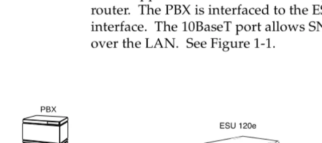
In this application, the base Nx54/64 provides a V.35 interface to a router. The PBX is interfaced to the ESU 120e with the base drop interface. The 10BaseT port allows SNMP network management over the LAN. See Figure 1-1.
Figure 1-1. Router, PBX, Application Set Up 1 4 SHIFT COPY ALARM CLEAR ESU 120e 7 2 5 8 0 # 3 6 9 HOME ENTER CANCEL
DSU/DSXOKTESTALARM
MODULEOKTESTALARM
CSUOKTESTERRORALARM
PBX
10 BaseT LAN
Chapter 2
Installation
UNPACK, INSPECT, POWER UP
Receipt Inspection
Carefully inspect the ESU 120e for any shipping damages. If you suspect damage, file a claim immediately with the carrier and then contact ADTRAN Customer Service (see inside the last page of this manual). If possible, keep the original shipping container for use in shipping the ESU 120e back for repair or for verification of damage during shipment.
AD TRAN Shipments Include
• The ESU 120e
• A DB-25 to modular adapter for VT-100 and T-Watch access. • An 8-position modular cable for connection to the chain-in port
(6 ft.)
• The user manual
Customer Provides
• Power cord
• Cable(s) for connection to either the 120 Ω DB15 or 75 Ω BNC network interfaces
Chapter 2. Installation
Power Connection
Power is supplied to the ESU 120e through a IEC-type power con-nector on the rear of the unit.
Power to the ESU 120e must be from a grounded 90-240 VAC,
50/60Hz source.
GROUND ING INSTRUCTIONS
Grounding instruction information from the Underwriters'
Labora-tory UL 1950 3rd Edition is provided in this section.
An equipment grounding conductor that is not smaller in size than the ungrounded branch-circuit supply conductors is to be installed as part of the circuit that supplies the product or system. Bare, cov-ered, or insulated grounding conductors are acceptable. Individu-ally covered or insulated equipment grounding conductors shall have a continuous outer finish that is either green, or green with one or more yellow stripes. The equipment grounding conductor is to be connected to ground at the service equipment.
The attachment-plug receptacles in the vicinity of the product or system are all to be of a grounding type, and the equipment grounding conductors serving these receptacles are to be connected to earth ground at the service equipment.
A supplementary equipment grounding conductor shall be installed between the product or system and ground that is in addi-tion to the equipment grounding conductor in the power supply cord.
Chapter 2. Installation
Code, ANSI/NFPA 70. Termination of the supplementary equip-ment grounding conductor is permitted to be made to building steel, to a metal electrical raceway system, or to any grounded item that is permanently and reliably connected to the electrical service equipment ground.
Bare, covered, or insulated grounding conductors are acceptable. A covered or insulated grounding conductor shall have a continuous outer finish that is either green, or green with one or more yellow stripes.
Chapter 2. Installation
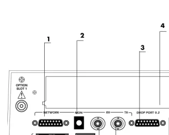
ID ENTIFICATION OF REAR PANEL LAYOUT
Figure 2-1 shows the configuration of the rear panel of the ESU 120e.
Figure 2-1. ESU 120e Rear Panel
1 Network 120 ΩΩΩΩ Connector 7 Control In/Out Connection
2 Network Receive Monitor Jack 8 10BaseT Connector (To LAN for Management)
3 Drop Port Connector (To PBX) 9 Network 75 ΩΩΩΩ Receive Connector
4 Option Slot 10 Network 75 ΩΩΩΩ Transmit Connector
5 Power Switch 11 Data Port Connector
6 IEC Power Connector 12 Fuse Tray
2 1
3 4
5 6
7 8 9 10 11
Chapter 2. Installation
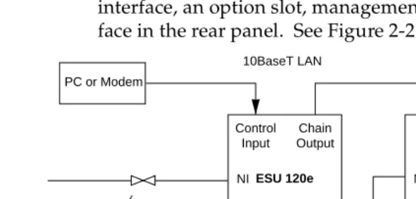
ESU120E INTERFACES
The ESU 120e is equipped with an Nx56/64 data port, a G.703 drop interface, an option slot, management interfaces, and an E1 inter-face in the rear panel. See Figure 2-2.
Figure 2-2. ESU 120e Interfaces
Network Interfaces
The Network Interface (NI) port provides the connection to the E1. This port complies with the applicable ANSI and CCITT standards. Either the 120Ω DB15 or the 75Ω BNC interface may be used for the Network Interface. The 75/120 selection must be made with the front panel menus. For more information see Wiring on page B-1.
Network Test Interface
The MON test jack provides a bridged access jack for non-intrusive monitoring of the incoming E1.
Nx56/ 64 Serial Interface
The Nx56/64 provides a serial interface that operates from 56kbps
ESU 120e
PC or Modem
Network
Control Input
Chain Output
NI ESU 120e
Chain Input Chain Output NI Option Option Drop Nx56/64 Nx56/64 Drop
PBX V.35 PBX-1
10BaseT LAN
RS530, V.11
Chapter 2. Installation
D rop (PBX) Interface
The drop interface provides a G.703 interface for a PBX or other equipment.
Control Port Input
The control port input provides an EIA-232 input from a PC or a modem for control of the ESU 120e. You can also use it as a chain input from another ESU 120e or ESU 100. For more information see Wiring on page B-1.
Chain Port Output
The chain port output provides an EIA-232 output to chain control to other ESU 120es. For more information see Wiring on page B-1.
10BaseT Interface
The 10BaseT interface provides the LAN interface for managing the ESU 120e with SNMP or T-Watch Pro. For more information see Wiring on page B-1.
POWER-UP TESTING
When shipped from the factory, the ESU 120e is set to factory default conditions. At the first application of power, the unit auto-matically executes a memory self-test. A full self-test can be run from the front panel, and a pass code and unit ID may be set using the UTIL menu.
Self-Test
Chapter 2. Installation
Board-level tests
Each of the ESU 120e boards contains an on- board processor which executes a series of tests checking the circuitry on the board. • RAM and EPROM tests.
• Verify on-board circuitry.
Unit-level tests
• Front panel LED verification.
• Board-to-board interface test. A test pattern is sent from the controller through a loopback on all other boards and checked on the controller. This verifies the data path, clocks, and control signals for the entire chassis.
Initialization
Set User Passcode
The ESU 120e is designed to operate with or without the use of a passcode. The default condition is without a passcode.
If the unit is to be remotely accessed using T-Watch PRO you must enter a passcode. When managing a number of units, the passcode can be the same for all the units.
The passcode should be a number easily remembered. Once entered, the passcode is required to access any operation other than viewing. See Set Passcode on page 6-2 for details.
Set Unit Identification
Chapter 2. Installation
Set Control Port
The ESU 120e can be configured from the control port when T-Watch PRO, SNMP, or the terminal interface are being used.
If the control port is to be used, the control port baud rate must also be selected.
Chain In (PC)
The unit can be controlled from an external PC connected directly or via modem to the chain-in port. when using chain-in, the selec-tion of the control port baud rate from 9600 (factory default), 1200, 2400, or 4800, or 38400 must be made using the Unit Configuration menu. See Unit Menu on page 5-11 for details.
Unless locked out externally, the front panel can also control the unit.
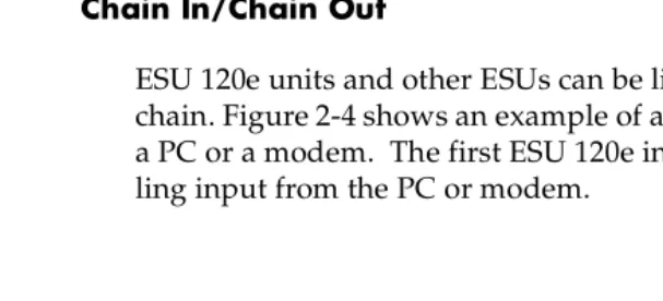
Chain In/ Chain Out
ESU 120e units and other ESUs can be linked together to form a chain. Figure 2-4 shows an example of a chain-in arrangement with a PC or a modem. The first ESU 120e in the chain receives control-ling input from the PC or modem.
Figure 2-3. Example of Chain In
ESU 120e
PC or Modem
Chapter 2. Installation
Subsequent ESUs in the chain are in a position to intake informa-tion from another ESU. This in-taking of informainforma-tion from another ESU in the chain is identified as chain in. The baud rate for the chained units must match that of the first unit.
Unless locked out externally, the front panel can also control the unit.
At this point, the Unit Initialization procedure is concluded. If the unit is to be configured remotely, there are no additional items nec-essary to complete prior to executing remote configuration.
The Passcode, the Unit ID, and the Control Port settings are stored in a nonvolatile memory. This assures they are operable for subse-quent power-up sequences.
NORMAL POWER-UP PROCED URE
After the unit has been put into operation with the initial power-up and initialization, subsequent power-up procedure includes only the Power-Up self-test followed by the request for a passcode (password) if this option was selected during initialization.
Chapter 3
O peration
FRONT PANEL
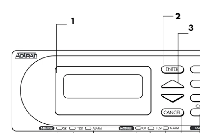
The ESU 120e front panel monitors operation and controls the con-figuration of the unit. The ESU 120e front panel is shown in Figure 3-1. Descriptions of each part of the front panel follow.
Name Description
LCD Window Displays menu items and messages in two lines by 16 characters. It also displays alarm and status information. Enter Key Selects active menu items. To select a menu item, press the
number of the item. The menu item flashes, indicating it is activated. Press Enter to select the menu item.
Up and Down
Arrows
Up
and
Down Arrows
scroll through and activate thesubmenu items available in the current menu. When the submenu items are scrolled, the flashing cursor indicates the active parameters.
Cancel Key Pressing the Cancel key stops the current activity and returns to the previous menu. Repeat until the desired menu level is reached. When a submenu item is displayed, press Cancel to exit the current display and return to the previous menu. Numeric
Keypad
The numeric keypad contains the numbers 0 through 9 which are used to activate menu items and enter information (such as the IP address).
Shift(entering special function keys)
Chapter 3. O peration
Figure 3-1. ESU 120e Front Panel Layout
No Name Description
1 LCD Window Displays menu items and messages
2 Enter Selects active menu item
3 Up and Down Arrows Scrolls through/activates submenu items
4 Alarm Quick access to the active alarm display menu
5 Clear Clears data/results fields
6 Shift Provides access to special function keys
7 DSU/Drop
8 OK (DSU/Drop status) Data and Drop parts is in normal mode with no errors
9 Test (DSU/Drop Status) Active when Data or Drop Port is in test mode
10 Alarm (DSU/Drop Status) Active when alarm condition has been detected on Data or Drop Port
11 OK (Module Status) Operation is in normal mode with no detected errors
12 Test (Module Status) Active when the module is in test mode
13 Alarm (Module Status) Active when an alarm condition has been detected
14 Cancel Stops current activity and returns to the previous menu
15 Copy Copies last data entered into the current TS0
16 OK (CSU Status) Operation is in normal mode with no detected errors
17 Test (CSU Status) Active when network interface is in test mode
18 Error (CSU Status) Indicates errors such as BPV, OOF, and CRC
19 Home Returns to main menu
20 Alarm (CSU Status) Active when alarm condition detected on the network interface
2 4 5
1
6
7 8 9 10 11 12 16 17 18
19 3
14 15
Chapter 3. O peration
LED D escriptions
CSU Status
The CSU status LEDs display the operational condition of the network interface located on the controller board in the unit.
D SU/ D rop Status
Name Description
OK (green) Indicates the operation is in the normal mode and no errors have been detected.
Test (yellow) Indicates that the network interface is operating in a test
mode. This includes a self-test or a test loopback. When lighted, this LED also indicates that normal data flow is not occurring on the network interface.
Error (red) Indicates an error such as a BPV, OOF, or CRC.
Alarm (red) Indicates an alarm condition has been detected. When the alarm condition is no longer valid, the OK LED activates (turns on). To view an alarm condition, select the active alarm menu item or select Alarm by pressing
Shift 8. If the alarm conditions have been corrected, the
alarm which caused the activation of the Alarm LED can be viewed under the Unit History menu.
Name Description
OK (green) Indicates the operation is in the normal mode and no errors have been detected.
Test (yellow) Indicates that the interface is operating in a test mode.
This includes a self-test or a test loopback. When lighted, this LED also indicates that normal data flow is not occurring in at least one of the module ports.
Chapter 3. O peration
Module Status
Operation keys
Name Description
OK (green) Indicates the operation is in the normal mode and no errors have been detected.
Test (yellow) Indicates that one of the interfaces is operating in a test
mode. This includes a self-test or a test loopback. When lighted, this LED also indicates that normal data flow is not occurring in at least one of the module ports.
Alarm (red) Indicates an alarm condition has been detected. When the alarm condition is no longer valid, the OK LED activates (turns on). To view an alarm condition, select the active alarm menu item or select Alarm by pressing
Shift 8. If the alarm conditions have been corrected, the
alarm which caused the activation of the Alarm LED can be viewed under the Unit History menu.
Name Description
Copy Used in the TS0 mapping menu operations to copy the last data entered into the current TS0. This key operates without pressing the Shift key.
Home Returns home to the Main menu from any menu location.
Alarm Used as quick access to the active alarm display menus. This can be activated while any other menu item is in use. When the Alarm menu is exited, the unit returns to the location of the same menu that was active when Alarm was selected.
Chapter 3. O peration
General Menu Operation
The ESU 120e uses a multilevel menu structure containing both menu items and data fields. All menu operations and data are dis-played in the LCD window. The menu items are numbered and can be viewed by scrolling with the Up and Down arrows.
Select and Activate a Menu Item
To choose menu items, place the cursor on the desired menu item by pressing the number corresponding to the menu item or highlighting the menu item with the Up and Down Arrow. The following procedure describes how to activate the Alarm List option from the Status Menu.
Name Description
Data Field You can edit menu items followed by a colon (:).
Display Only Field
You cannot edit menu fields followed by an equal symbol (=). This symbol identifies a field used for value display only.
Arrows Menus that display small Up or Down Arrows in the
lower right corner indicate there are more menu items than are visible on a two-line LCD. Access the
additional items with the up or down arrows. You can also access undisplayed menu items by using the appropriate menu number.
Step Action Result
1 Activate the STATUS menu using the arrow keys or by pressing 1.
The cursor will flash on the number next to the activated selection.
2 Press Enter. Use the arrow keys to view
submenu items. 3 Choose an item on the
submenu such as ACTIVE ALARMS.
Chapter 3. O peration
The menu tree below shows front panel menu travel.
Figure 3-2. Example of Basic Front Panel Menu Travel
Set the D ata Field
You can edit data fields preceded by a colon (:). 1) NI PERF RPTS
2) NI ERRORS
3) ACTIVE ALARMS (ALARM LIST)
4)VIEW HISTORY END OF LIST
1)STATUS 5) PORT STATUS
6) REMOTE PORT 7) CLEAR PORT ALM 8) ENET STATUS
Step Action Result
1 With the cursor positioned on the submenu item number, press Enter.
The cursor moves to the data field, (to the right of the submenu item name). 2 Using the arrows, scroll to scan
the available value settings.
The value settings display one-at-a-time in the data field position.
3 When the desired value is displayed in the data field position, press Enter to set that value.
When the value is set, the cursor moves back to the submenu item position indicating the operation is complete.
4 Select another submenu field or press Cancel to return to the submenu.
Chapter 3. O peration
Exit Any Menu Field Operation Or D isplay
Press Cancel as many times as required to return to the desired menu level or press Home to return to the main menu.
D ata Port Identification
When configuring the unit, menu selections will include options from data port submenus. Selecting of data ports is necessary because the ESU 120e uses a Slot-Port method to identify which data port the menu item is referencing. If a module containing a PBX drop option card with an Nx56/64 plug-on interface is installed in the option slot, it would be designated as:
drop Passthru=1.1
Where slot=1 and port =1.
The drop is located in the option slot and is the first port in that slot.
Nx56/64=1.2
Where slot=1 and port=2.
The Nx is located in the slot and is the second port in that slot.
The ports that are built into the ESU 120e are referenced as Slot 0. The Nx56/64 would be designated as 0.1 and the drop would be referenced as 0.2.
Front Panel Menu Structure
The ESU 120e uses a multilevel menu structure containing both menu items and data fields. All menu operations and data display in the LCD window.
Chapter 3. O peration
The front panel LCD of the Main menu contains four options:
Status, Config, Util and test.
Alternate Methods of Control
T-Watch PRO (AD TRAN PC Program)
T-Watch PRO is the ADTRAN PC control program. It provides complete control over the configuration of the ESU 120e using a graphical interface. The T-Watch PRO program displays the same status and performance data as the front panel LCD. This data is displayed in the form of tables and graphs.
The T-Watch PRO program has the following capabilities:
• Interfaces with a modem which permits dialing into a remote ESU 120e location to configure the unit or read the status or per-formance of the unit.
• Receives traps from any ESU product.
• Records and creates display performance data over a 30-day period.
• Accesses units via the local area network.
Name Description
Status The Status Menu displays all relevant information
for the network and DTE interfaces. For detailed information on status options, see Status Menu in Chapter 4.
Config
(Configuration)
The Configuration Menu displays and sets the ESU 120e operational configuration, including all network interface parameters, the allocation of the TS0s, and the port parameters. For detailed information on configuration options, see Configuration Menu in Chapter 5.
Util (Utilities) The Utility Menu displays and sets system parameters. For detailed information on utility options, see Utility Menu in Chapter 6.
Chapter 3. O peration
To set up the ESU 120e to work with T-Watch PRO over the LAN, follow these steps:
To set up the ESU 120e to work with T-Watch PRO over a direct EIA-232 connection, the following steps are required:
Step Action
1 Set the Unit ID using the Front Panel. See Unit ID on page page 6-4 for details.
2 Set TCP/IP interface to 10BaseT (or SLIP) using the Front Panel.
3 Configure the IP address, default gateway, and subnet mask using the Front Panel.
4 Follow the installation instructions for T-Watch PRO to start the program and connect to the unit.
Step Action
1 Set the Unit ID and set a passcode using the Front Panel. See Unit ID on page 6-4 and Set Passcode on page 6-2 for details.
2 Set the control port rate to the same setting as the PC Com port.
3 Connect the PC Com port to the Chain-In port on the ESU 120e using the DB25 adapter and modular cable provided.
Chapter 3. O peration
SNMP
The ADTRAN ESU 120e supports the Simple Network Manage-ment PROtocol (SNMP) through the 10BaseT or chain in (SLIP) interface. See Appendix A, for information on SNMP.
To use SNMP with the ESU 120e, do the following:
Terminal Mode
The ESU 120e provides the front panel menus to a VT-100 type ter-minal. This mode can be used to configure and monitor the unit. Initiate this mode by typing <CTRL> PTT on the terminal once it is connected to the Control In port. For detailed information on this method of control, see Chapter 8, Telnet/Terminal Menus.
Telnet
You can connect to the ESU 120e via Telnet. Before attempting to connect via Telnet, first define the IP address, the default gateway, and the subnet mask using the front panel. When you begin the Tel-net session, you will be prompted for a password. The default pass-word is ADTRAN. You can change this passpass-word using the Management submenu. The Telnet session will time out after a pre-defined value that is also set in the Management menu.
Only one Telnet session can be active at one time.
Step Action
1 Set TCP/IP access as either 10BaseT or SLIP (Chain In Port).
2 Set the IP address, default gateway, and subnet mask through the front panel.
3 The appropriate MIB browser must be loaded into the Network Management Station (available on the ADTRAN webpage at http://www.adtran.com).
Chapter 4
Status Menu
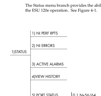
The Status menu branch provides the ability to view the status of the ESU 120e operation. See Figure 4-1.
1) NI PER F R PTS
2) NI ER R O R S 1)STA TUS
3) A CTIVE A LA R MS
4)VIEW HISTO R Y
1) DTE DA TA /CK
5) PO R T STA TUS 0.1 Nx56/64 2) DTE STA TUS
3) PO R T R A TE 6) R EMO TE PO R T
0.2 DR O P MENU ITEMS 7) CLEA R PO R T A LM
Chapter 4. Status Menu
Menu flow is normally depicted from left to right. Arrows on the lower right of the screen indicate the direction of scrolling to use to view additional menu items. At every level of the menu, pressing
Cancel returns the system to the previous menu level. Pressing
Cancel repeatedly returns the system to the Main Menu.
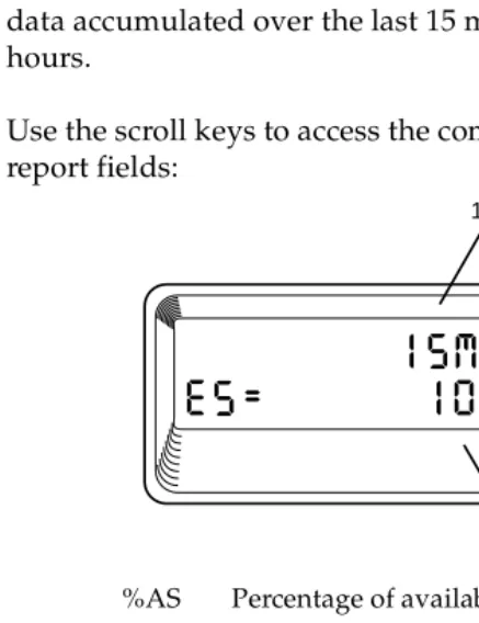
Network Interface Performance Reports (NI PERF RPTS)
The Network Interface Performance Reports display the user’s copy of the performance data. The ESU 120e maintains this perfor-mance data on the network based on G.821. The data displayed is data accumulated over the last 15 minutes and over the last 24 hours.
Use the scroll keys to access the complete display of the following report fields:
Figure 4-2. Network Interface Performance Report %AS Percentage of available seconds
BES Between 2 and 832 errors/sec %EF Percentage of error free seconds
DM Number of minutes with bit error rate of 1 x 10⁻⁶ or greater
ES Number of errored seconds (1 or more errors/ second)
SES Number of severely errored seconds (more than 832 CRC errors/sec). Approximate equivalent to a bit error rate of 1 x 10⁻³ UAS Number of unavailable seconds (10 or more
consecutive seconds) 15 Minutes
24 Hours
Chapter 4. Status Menu
If insufficient time has passed to collect data, NA displays. Con-tinue with standard operating procedures to exit the display.
When this menu is active, performance data can be cleared by pressing Clear (Shift 9) on the keypad. Only the user ’s copy of the performance data is cleared.
Since only the user ’s copy of performance data is cleared by the ESU 120e, the data displayed here might be different from the data sent to the network as PRM data.
Network Interface Errors (NI ERRORS)
The NI Errors submenu displays the types of errors the Network Interface (NI) detects. A blinking CSU error LED indicates that net-work errors are detected.
The asterisk (*) above an item indicates the type of errors detected. The error types are the following:
Active Alarms
This menu item displays a list of current alarms reported by either the base controller or any of the ports. If no alarms are current, using this menu item displays End of List.
This display includes two lines of text. The top line is the alarm source. The bottom line is the alarm message. A list of alarm mes-sages is found in the appendix, ESU 120e System Mesmes-sages.
CRC CRC-4 bit errors. This is valid only if CRC-4 mode is enabled.
BPV Bipolar violations.
XS0 Excess zeros.
Chapter 4. Status Menu
In addition to normal menu operation, you can also access this menu item with the Alarm function (Shift 8) on the keypad. If one or more of the Alarm LEDs are illuminated, an alarm is present. Pressing Cancel returns to the previous menu item.
Figure 4-3. D isplay of Alarm Messages
View History
This menu item both displays and clears the accumulated status changes of the unit.
View History displays a history of the first 20 status changes in the unit, including the date, time, and type of change. The unit also records for viewing, the date and time an alarm became active or inactive, as well as the date and time of test activation or deactiva-tion.
To clear the View History display, press Clear (Shift 9) with the View History menu active.
Alarm Source
Chapter 4. Status Menu
Port Status
Port Status displays the signals monitored on the data ports. For example, the Nx56/64 interface monitors the RTS, CTS, RD, and RD, along with other signal lines. When a port is selected, the LCD indicates if the signal is present.
The base Nx interface offers the status screen listed in this section. When using other option cards, refer to the appropriate User’s Manual for a definition of any status screens offered.
The Port Status of Nx56/64 is examined as an example of how to use this item.
0.1 Nx56/ 64 Menu Items
D TE D ata/ CK
An asterisk (*) indicates an active status of the following lines.
D TE Status
An asterisk (*) indicates an active status of the following lines:
Port Rate
TXD Transmit data from the DTE
RXD Receive data toward the DTE
ETC External Transmit Clock from DTE
LCK Lock Status of the phase locked loop
RTS Request to send from DTE
CTS Clear to send to DTE
DCD Data carrier detect to DTE
Chapter 4. Status Menu
0.2 D rop Menu Items (D SX Errors)
Remote Port
Remote Port displays the status of activity on the Control In remote port. This is useful for troubleshooting communication sessions, and for verifying cabling.
Clear Port Alarm
Clears the Link Failed alarms on option modules that have been removed from the ESU 120e chassis.
ENET Status
CRC An asterisk displays under the CRC if there are CRC errors in extended superframe format (ESF) mode. If CRC-4 is not enabled on the Drop Port, the LCD displays n/a.
BPV An asterisk displays under the BPV if the Drop Port detects bipolar violations.
SLIP An asterisk displays under the SLIP if the drop plug-on board detects frame slips. This is caused by multiple clock sources in the application.
FER An asterisk displays under the FER if the Drop Port detects frame bit synchronization errors.
RX Characters received at remote port
ID Unit ID received at remote port
CR C
Correct CRC received
PC Correct passcode received
TX Characters transmitted from the remote port
TX Indicates that data is being transmitted from the 10BaseT port
RX Indicates that data is being received by the 10BaseT port.
LN K
Indicates the current status of the 10BaseT link integrity test (this should always be on when the unit is connected to a functional 10BaseT hub.
Chapter 5
Configuration Menu
The Configuration menu sets the ESU 120e operational configura-tion, including all network interface parameters, the allocation of the DS0s, and the port parameters. See Figure 5-1 on page 5-2.
Menu flow is normally depicted from left to right. Arrows on the lower right of the screen indicate the direction of scrolling to use to view additional menu items. At every level of the menu, pressing
Cancel returns the system to the previous menu level. Pressing
Chapter 5. Configuration Menu
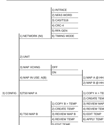
Figure 5-1. Configuration Menu Tree
1) INTFACE 1) CTL PORT 2) NFAS WORD 2) TRAPS 3) CAS/TS16 3) ACCESS 4) CRC-4 4) INIT MODEM 5) RFA GEN 5) EXIT TERM MODE 1) NETWORK (NI) 6) TIMING MODE 6) IP INTERFACE
7) IP ADDRESS 8)SUBNET MASK 9)DEFAULT ROUTER 2) UNIT 10) SLIP RATE
A) SLIP FLOW CTL 3) MAP XCHNG OFF B) PROXY TRAPS
ON
4) MAP IN USE: A(B) 1) MAP A @:HH:MM 2) MAP B @:HH:MM
3) CONFIG 5)TS0 MAP A 1) COPY A > TEMP 1) INTERFACE 2) CREATE TEMP 2) DSO RATE 1) COPY B > TEMP 3) REVIEW MAP A 3) TX CLK CNTRL 2) CREATE TEMP 4) REVIEW TEMP 4) DATA 6) TS0 MAP B 3) REVIEW MAP B 5) EDIT TEMP 5) CTS
4) REVIEW TEMP 6) APPLY TEMP > A 6) DCD 5) EDIT TEMP 7) DSR 6) APPLY TEMP > B 8) “0” INHIBIIT
9) INBAND A) TX CLK SOURCE
0.1 NX56/64 7) PORT CONFIG
Chapter 5. Configuration Menu
NETWORK (NI)
This menu item accesses the configuration of parameters associated with the network interface in the base unit. There are eight sub-menu items that include setting the format, the line build out (LBO), and the timing mode.
Network (NI) Menu Items
The menu items are:
Menu Item Description
Interface (INTFACE)
Selects either the 120Ω DB15 interface or the 75Ω BNC interface.
Choices: 120Ω, 75Ω. BAL and 75Ω UNBAL
In 75Ω UNBAL mode, both the Tx and Rx are shield grounded.
Framing NFAS Word. If enabled, the network interface receiver requires the NFAS word (TS0 in odd frames) and the FAS word (TS0 in even frames) for frame sync. When disabled, only the FAS word is needed for frame sync.
Choices: Enable, Disable
CAS/TS16 Enables/Disables Channel Associated signalling (time slot 16 multiframing). When this menu option is enabled, the following occurs:
1. The TS16 multiframe alignment signal is inserted in the outgoing data stream.
2. Signaling Bits are transmitted in TS 16 for all TS0s that are mapped to a signalling-capable port (Base Drop port, for example). In TS0s that are mapped to “Idle” or data ports, “1s” are transmitted in the signalling bit positions.
Chapter 5. Configuration Menu
• Note that if CAS/TS16 is enabled, TS16 may not be mapped to a port, and will be forced to “Idle”. When CAS/TS16 is disabled, and TS16 is mapped to a port, the data in TS 16 will be mapped through from the network to the mapped port. For common channel signalling ap-plications, CAS/TS16 should be disabled and TS16 mapped to the drop port. TS16 may also be mapped to the base Nx56/64 or an option module data port. • When CAS/TS16 is enabled, TS16 is forced to idle in DS0
Map A and B and may not be mapped. This configura-tion must be used if there are multiple signalling-capable ports that are mapped to the Network Interface. For ap-plications where the Base Drop Port requires channel as-sociated signalling, (connection to a PBX, for example) CAS/TS16 must be enabled and TS16 left idle in the DS0 Map.
CRC-4 When this option is enabled, the CRC-4 checksum bits are transmitted in the outgoing E1 data stream. Also, the received signal is checked for errors.
Choices: Enable, Disable
RFA Gen When enabled, remote frame alarm is transmitted toward the Network during alarms.
Choices: Enable, Disable Timing
Mode
Selects the clock source for transmission toward the network from the NI. See ESU 120 Clock Sources on page 5-5 for more information.
Chapter 5. Configuration Menu
ESU 120e CLOCK SOURCES
The ESU 120e is operable from various clock sources permitting it to perform properly in many different applications. Set the net-work interface clocking options with the clocking options set by the Network (NI) Configuration menu options.
The following clock source options are available:
• Network Timed • Base Drop Timed • Base DTE Timed • Internal Timing
• Normal (CSU) (only when secondary interface module is in-stalled)
Chapter 5. Configuration Menu
Network Timed
The network is the source of timing. The received data clocking is looped back to the network where it is used to determine the trans-mission timing. This option is also referred to as loop timed as the transmission clock is derived from the received clock. See Figure 5-2.
Figure 5-2. Network Timed Clock Source
DTE OSC
Secondary Interface
( O P T I O N )
Network Interface E1 XMIT
E1 Receive
Nx56/64
DTE CLOCK
Drop Port
Chapter 5. Configuration Menu
Base D rop Timed
The PBX is the source of timing. The ESU 120e uses the clock derived by the Base Drop interface for transmission timing (see Fig-ure 5-3).
Figure 5-3. D rop Timed Clock Source
DTE OSC
( O P T I O N )
Network Interface E1 XMIT
E1 Receive
Nx56/64
DTE CLOCK
Drop Port
Chapter 5. Configuration Menu
Base D TE Timed
The DTE is the source of timing. The ESU 120e uses the incoming DTE clock to determine the transmission timing. This is typically used in applications where it is necessary to have the DTE as the primary clock source, (such as limited distance line drivers). See
Figure 5-4.
Figure 5-4. Network Timed Clock Source
DTE OSC
( O P T I O N )
Network Interface E1 XMIT
E1 Receive
Nx56/64
DTE CLOCK
Drop Port
Chapter 5. Configuration Menu
Internal Timing
The ESU 120e is the source of timing. The ESU 120e is configured to use its own internal oscillator as the source of timing. Applica-tions include private line driver circuits where one end is set to net-work and the other to internal. See Figure 5-5.
Figure 5-5. Internal Clock Source
DTE OSC
( O P T I O N )
Network Interface E1 XMIT
E1 Receive
Nx56/64
DTE CLOCK
Drop Port
Chapter 5. Configuration Menu
Normal (CSU) Timing
The typical timing option arrangement is shown in Figure 5-6. The PBX is looped timed sending data to the ESU 120e which is actually synchronous to the received data. The Network Interface (NI) is the actual source of all timings. This timing option is the same as that typically used for CSUs. This is the preferred mode for use with a PBX application.
This timing mode works equally well when the PBX is the source of timing. In that configuration the network would not be providing timing.
Figure 5-6. Normal (CSU)
The network interface and secondary interface clocking options are set by using the Network (NI) Configuration menu options.
DTE OSC
Secondary Interface
(SI)
( O P T I O N )
Network Interface
(NI)
E1 XMIT
E1 Receive
Nx56/64
DTE CLOCK
Drop Port
PBX
(IO PB)
Chapter 5. Configuration Menu
Unit Menu
The Unit menu changes the baud rate of the Control In port and the setup of the Dial Out port. The menu items are:
Menu Item Description
Ctl Port Sets the baud rate for communication with the PC or modem.
Choices: 1200, 2400, 9200, 9600, and 38400 kbps Traps Enables or disables the transmission of trap
messages.
Choices: Enable and Disable
Access Sets the method of connection from the ESU 120e to T-Watch/SNMP.
Choices:
Direct - Used if connected directly to the PC. Dial - Used when connection is through a modem. The dial string is entered from T-Watch/SNMP. Init Modem Allows you to choose an industry standard or a
custom initialization string for a modem connected to the control port.
Choices: Industry standard and Custom Initialization String
Exit Term Mode Takes the unit out of terminal mode.
IP Interface Selects the TCP/IP physical interface; 10-Base-T Ethernet or SLIP using the EIA-232 serial port. Choices: 10-Base-T Ethernet or SLIP
If this option is set to SLIP, the EIA-232 port
may not be used as a terminal interface.
Chapter 5. Configuration Menu
Subnet Mask This defines which part of a destination IP address is the Network number. It is used along with the ESU 120e IP address to determine which nodes must be reached through the default IP Gateway. This value is set to 0.0.0.0 when the IP interface option is set to SLIP.
Default Router All IP Packets destined for nodes not on the ESU 120e unit’s local network are not forwarded through this IP address. Normally, this address defines a router connected to the ESU 120e unit’s local
network. This value is ignored when the IP interface is set to SLIP.
SLIP Rate This sets the baud rate for the Chain-In port when used as the SLIP connection for SNMP management. Choices: 1200, 2400, 9600, 19200, 38400
SLIP Flow CTL This is used to activate flow control on the Chain-In port when used as the SLIP interface. Hardware mode uses RTS and CTS.
Choices: None, Hardware
Proxy Traps This determines which interface is used for forwarding traps from units being “proxied” for. Choices: 10 BaseT, Chain-In
Chapter 5. Configuration Menu
Map Exchange (Map Xchng)
The Map Exchange menu enables and sets the automatic time of day map switch. The unit provides selection of the hour, minute, and seconds for the map switching to take place. The menu items are:
Map In Use: A(B)
This menu item controls the TS0 map the ESU 120e uses and dis-plays the map in current use.
Menu Item Description
OFF Indicates the map in use does not change (disabled). ON Indicates that the map in use will change at a
user-selected time of day (enabled).
Scroll to select Auto to enable or Off to disable the Automatic Map Change feature and press Enter to activate the selection.
When Auto is selected, the unit displays the screens to set times for switching. After editing Map A, press Enter to record the Map A settings and activate the selection fields for Map B. Use the same
Chapter 5. Configuration Menu
TS0 Map A and TS0 Map B
The TS0 maps designate which TS0s are assigned to which port. There are three maps, TS0 Map A, TS0 Map B, and the Temporary (Temp) map. See Figure 5-7.
Figure 5-7. D S0 Map D esignations
TS0 A and TS0 B are the current maps the ESU 120e uses. The Temp map generates a map before putting it into use.
You can copy TS0 A to TS0 B by copying the TS0 A map into the TEMP map. Then apply (write) the TEMP map into TS0 B.
T E M P
Chapter 5. Configuration Menu
The menu items are:
Menu Item Description
COPY A >TEMP This copies the current map (A or B) into a TEMP map area. This permits modification without disturbing the existing map. When the modifications are completed, the TEMP map is written to current MAP A (B) by selecting Apply.
CREATE TEMP This creates a map by defining a port or Idle for all TS0s. When CREATE TEMP is first selected, all TS0s are set to Idle.
PORT: IDLE, TST, + option module ports
TST designates which TS0s are used for QRSS testing when activated under the 4)TEST Menu. When not used for testing, the TST designation is identical to IDLE.
With the cursor on CREATE TEMP, press Enter. The unit displays the selection screen with the cursor positioned on the first selection TS0 number. See Figure 5-8.
Figure 5-8. Create Temp Selection Screen Use either the scroll method or numbers to enter the TS0 number (do not mix the use of the keys). Pressing
Enter completes the selection and moves the cursor to
Select DS0 Number
Chapter 5. Configuration Menu
Scroll to select the port which is dependent on the installed option card. Press Enter to complete the selection and move the cursor back to the TS0 field.With the cursor on the TS0 field, the TS0 number can be incremented or decremented by scrolling. If
Copy is pressed, the contents of the last TS0 entered are placed in the new TS0 number.When all entries are complete, Cancel moves the cursor to the last of the submenu choices, 6)APPLY. Either apply the newly created TS0 map or press Cancel to return to the TS0 Map A (B) submenu choices.
Selecting Apply will not disrupt the operation of unmodified ports
REVIEW MAP A(B)
Permits a quick review of the number of TS0s assigned to each port and the number of unassigned TS0s (Idle or TST) as defined in the currently applied Map A(B).
REVIEW TEMP This menu item is operated the same for the TEMP map as is 3)REVIEW MAP A or Map B.
EDIT TEMP The map in the TEMP file can be edited to whatever configuration is desired. If Map A had been copied into the TEMP file, then after editing, the TEMP file could be applied to MAP A or MAP B. The menu operation is identical to 2) CREATE TEMP with the exception that the existing port selections display. APPLY TEMP > A Writes the TEMP map into Map A. Apply is usually
the last step in updating a map and is accessed automatically at the end of editing or creating a temporary map. Currently, it can be bypassed by selecting another menu choice.
Chapter 5. Configuration Menu
Port Configuration (Port Config)
Port Configuration selects and configures the parameters associ-ated with any data port in the unit. For example, parameters for the Drop Port Interface (PBX) interface are set through this menu. The items that can be set depend on which option module is installed. The list of option ports will vary with the configuration.
The ESU 120e is designed so that any additional ports developed in the future will contain the appropriate menu selections to provide access by use of this menu item.
The Config menus for options ports are described in separate sec-tions of the manual supplied with the option card.
0.1 Nx56/ 64 Port Configuration (Port Config) Menu Items
The menu items are:
Menu Item Description
INTERFACE This option sets the electrical interface for the Base Nx56/64 port.
Choices: V.35, V.11 (X.21), RS530, V.36
TSO RATE This sets the base rate of the interface. The actual data rate depends on the number of DS0s assigned to the Nx port.
Choices: 56K or 64K
TX CLK CNTRL
Controls the clock used by the TSU 120e to accept transmit (TX) data from the DTE. The default is normal. If the interface cable is long, causing a phase shift in the data, the clock can be selected as Invert. This switches the phase of the clock which should compensate for a long cable.
Chapter 5. Configuration Menu
DATA Used to control the inverting of the DTE data. This inversion can be useful when operating with an HDLC protocol. Often used as a means to ensure 1s density.
Choices: Normal or Invert
If Invert is selected, zero (0) inhibit should also be selected to prevent an open DTE input from placing zeros on the network.
CTS Used to control characteristics of CTS. Choices: Normal, (see Table 3-A) or Force On
DCD Data Carrier Detect. Indicates to the DTE when a valid signal is being received at the Network Interface.
Choices: Normal (see Table 3-A) or Force On
DSR Data Set Ready. This signal indicates to the DTE when the DCE is turned on and ready for operations.
Choices: Normal (see Table 3-A) or Force On
0 INHIB The Nx interface will detect an uninterrupted string of zeros (0s) being transmitted toward the network. If 0s are transmitted for >1 second, the TSU 120 will force 1s.
Choices: On or Off
INBAND The Nx56/64 port is capable of providing an inband communications channel (for T-Watch and SNMP) between units. This is accomplished by using 8 kbps of the first DS0 assigned to that particular Nx56/64 port. If in 56 K mode, no data bandwidth will be used. Inband must also be enabled at the destination port.
Choices: On or Off, On Demand
TX CLK SOURCE
This controls the source of the clock used by the TSU 120e to accept transmit data from the DTE. The default is Internal. If the application requires that the DTE device provides the clock with the transmit data, the External setting is used. Choices: Internal, External
Chapter 5. Configuration Menu
Table 5-1. Normal Mode of Operation
0.2 D rop Port Configuration (Port Config) Menu Items
The menu items are: RTS Signal V.54
Loop-back 511 TST ON Self Test Active Netwk Test Active No DS0 Mapped Network Alarm
CTS Follows OFF OFF OFF OFF OFF OFF
DCD — — — OFF — OFF OFF
DSR — OFF OFF OFF OFF OFF —
Where “—” = don’t care
*Until backup becomes active
Menu Item Description
NFAS Word NFAS Word. If enabled, the network interface receiver requires the NFAS word (TS0) in odd frames) and the FAS word (TS0 in even frames) for frame sync. When disabled, only the FAS word is needed for frame sync. Choices: Enable, Disable
CAS/TS16 Enables/Disables Channel Associated signalling time slot 16 multiframing). When this menu option is enabled, the following occurs:
1. The TS16 multiframe alignment signal is inserted in the outgoing data stream (toward the PBX).
2. Signaling Bits are transmitted in TS 16.
3. The TS16 multiframe alignment signal must be received for frame sync.
If CAS/TS16 is enabled on the Drop Port, it must also be enabled on the Network Interface.
Chapter 6
Utility Menu
The utility menu tree displays and sets system parameters (see Fig-ure 6-1). This includes setting the time and date, resetting all parameters to factory values, or re-initiating the unit. This menu also displays the unit software revision and the unit ID setting.
TIME: HH:MM:SS 1) TIME/DA TE DA TE: MM/DD/YY
(R eturns all configurations 2) FA CTO R Y R ESTO R E to factory settings)
3) SET PA SSCO DE 3) UTIL
4) UNIT ID
5) SO FTWA R E R EV (Displays Current Software R evision
6) PO R T UTILITY
Chapter 6. Utility Menu
Menu flow is normally depicted from left to right. Arrows on the lower right of the screen indicate the scrolling direction to view additional menu items. At every level of the menu, press Cancel to return the system to the previous menu level. Pressing Cancel repeatedly returns the system to the Main menu.
Time/ D ate
This menu option displays or edits the current time and date. The ESU 120e maintains the time and date during power-off conditions.
Pressing Enter after any numeric change always records the entry and moves to the next editing position. You can also move to a dif-ferent field to edit by pressing Enter at the editing position without making any change, or by using the Up and Down Arrow keys. Pressing Cancel at any time ends the editing process.
Factory Restore
This menu item restores the factory default settings for all unit parameters, including configured TS0 maps.
Set Passcode
Enter Passcode from Other Menus
The Passcode prompt may make an unexpected appearance from other menu operations. This happens only when the unit is operat-ing in the limited access mode, i.e., without an active passcode. The limited access mode may become active even if a passcode was entered as it does when there is no activity for ten minutes. If the unit is to be remotely accessed using T-Watch PRO, a passcode must be entered. When managing a number of units, the passcode can be the same for all.
Chapter 6. Utility Menu
Pressing any key after entering a passcode causes the unit to return to the previous active menu. In this case it returns to 2)CONFIG, 2)UNIT, 1)CNTRL PORT, 1)DATA RATE to permit changing the data rate.
Change/ Set a Passcode
The passcode can be changed or set at any time or eliminated alto-gether through the Utility menu item 3)SET PASSCODE. This pro-cedure requires the current passcode (if one is established) for operation.
The passcode can only be entered by using numbers. After enter-ing the desired passcode, press Enter.
Set a null passcode at the 3)SET PASSCODE menu by pressing
Enter without any numbers. This sets a null passcode and grants unlimited access.
Special Feature
For added security protection the unit is equipped with an auto-matic time-out for operation with the password. After ten minutes of inactivity, the unit reverts to limited access operation. To make changes in the configuration, the passcode can be reentered. If the passcode number is lost, contact ADTRAN Customer Service for assistance.
No Passcode D esired
At the New Passcode prompt (in the Set Passcode menu), press
Chapter 6. Utility Menu
Unit ID
This menu is used to access the current Unit ID setting. Viewing is available in limited access mode. Editing or changing the Unit ID requires the use of a password as in editing mode. Unit Identifica-tion numbers must be between 2 and 250. If an out-of-range num-ber is entered, the unit assumes the upper limit numnum-ber of 250.
To Set the Unit Identification
In the Unit ID menu (item 4) under the UTIL menu, enter any value between 2 and 250. The number 1 is reserved for the PC.
Pressing Enter records the Unit ID number and establishes its avail-ability for operation by remote control. The unit proceeds to the Set Control Port prompt.
No Unit ID D esired
Without entering any numbers at the Unit ID prompt, press Enter. Pressing Enter with no Unit ID recorded establishes the unit as not able to be operated by remote control.
Software Revision (Software Rev)
This menu provides access to the display of the current software revision level loaded into the base unit controller. This information is required when requesting assistance from ADTRAN Customer Service or when updates are needed.
Chapter 6. Utility Menu
Port Utility
This menu provides access to the display of the current software information for each port installed in the unit. This information is required when requesting assistance from ADTRAN customer ser-vice or when updates are needed.
Enet Address
Displays the Ethernet address for the 10BaseT port.
CMD Mode
Chapter 7
Test Menu
The Test menu initiates different types of unit tests and displays test results in the LCD window. The Test menu contains four items. See Figure 7-1.
Executing tests will disrupt some of the normal operation. See individual menu items concerning tests before executing.
LINE ON
FE1 LOOPBACK
1) LOCAL LOOPBCK PAYLOAD ON
NO LOOPBACK
1) NETWORK TESTS
2) TEST PATTERN ALL ZEROS
QRSS ALL TS0S
QRSS TST TS0S
ALL ONES
5)TEST NONE
3) PATTERN RESULT (Displays results)
2) RUN SELF-TEST 1) LOOPBCK
2) 511 PATT
3) PORT TEST 0.1 NX56/64 3) DISP 511 RESLT
Chapter 7. Test Menu
Menu flow is normally depicted from left to right. Arrows on the lower right of the screen indicate the scrolling direction to view additional menu items. At each level of the menu, pressing Cancel returns the system to the previous menu level. Pressing Cancel repeatedly returns the system to the Main menu.
Network Tests
Network tests control the activation of loopbacks and the initiation of data test patterns.
Network tests are run on the Network Interface (NI). You can select three different test configurations to determine the type of loopback and the pattern to run. Test results display in the LCD window.
Executing Network Tests will disrupt normal data flow unless only TST TS0s are selected for testing.
Loopback Tests
A number of different loopbacks can be invoked locally from the front panel, by T-Watch commands, or remotely by using special in-band codes (AT&T D4 network loop-up and loop-down codes). Additionally, the loopbacks can be remotely controlled by means of out-of-band commands by the E1 ESF FDL or from T-Watch PRO via a modem connection.
Network Interface Loopbacks
Network interface loopbacks (see Figure 7-2 on page 7-3) affect the entire E1 data stream. There are two types of network loopbacks, line loopback and payload loopback.
Line loopback loops all of the received data back toward the net-work. The transmitted data is the identical line code that was received, including any bipolar violations or framing errors.
Chapter 7. Test Menu
Figure 7-2. Network Loopback Tests
LOCAL LOOPBCK
There are three available choices for setting the local loopback:
Scroll to select a setting and record it by pressing Enter. The unit returns the display of 1)LOCAL LOOPBCK and 2)REMOTE LOOP-BCK
REMOTE LOOPBCK
FE1 Loopback sends V.54 loopback code in all mapped TSOs toward the network. Far end will respond by initiating a local line loopback.
TEST PATTERN
All Ones
Sends an all ones pattern to the network.
Line On Activates the line loopback
Payload On Activates the payload loopback
No Loopback Deactivates the loopback
ESU 120e
E1
NI CSU
Payload Loopback Line Loopback
Chapter 7. Test Menu
QRSS Pattern
The QRSS pattern is commonly used to simulate real data in E1 interfaces. This pattern can be assigned to appear in all TS0s or only in TST TS0s. When QRSS is set in all TS0s and one of the net-work loopbacks previously described is activated at the far end, a total end-to-end integrity check can be run without the need for any external test equipment. When QRSS is assigned to TST TS0s, an integrity check of the link can be run along with normal data flow. The TST TS0s are user assigned as part of the TS0 Map.
This sets the pattern for the test and initiates the transmission of the pattern. The test is terminated by selecting None. The following patterns are available:
QRSS always runs at 64K/TS0.
For example, use the up and down arrows to select QRSS ALL TS0s. Press Enter to record the selection. The ESU 120e starts to generate a QRSS test pattern and inserts the pattern into all TS0s. To end the test, select None.
QRSS All TS0s Generates a QRSS test pattern and inserts the pattern into all TS0s
QRSS TST TS0s Inserts a QRSS pattern in those TS0s mapped as TST in the currently active map (A or B)
Chapter 7. Test Menu
PATTERN RESULT
Displays the results of the test currently active. Leaving and returning to this menu item does not interrupt the test.
Pressing 2 injects errors into the test pattern. These errors are detected by