BANERJI, AYAAN. Numerical Study of a Spark Assisted Compression Ignition (SACI) Engine Using the One-Dimensional Turbulence (ODT) Model. (Under the direction of Dr. Tarek Echekki).
Advanced combustion engine concepts like Spark Assisted Compression Ignition (SACI)
are being investigated to provide a solution to the ever-increasing need for novel methods of power
generation with high efficiency and low emissions. This study is conducted with the intent to
understand the operating conditions for the effective functioning of this combustion concept using
the one-dimensional turbulence (ODT) model. The stand-alone ODT model is formulated for
engine simulations and can compute chemical interactions in unsteady fluid conditions with a high
resolution, while offering computational economy. While spark ignition and compression ignition
engines are widely used, SACI combustion is a relatively new concept, which still faces challenges
to being accepted commercially. It offers better operating efficiency as well as greater control over
combustion over a wide load range but involves numerous operational complexities for effective
combustion control. This study investigates the effect major engine operational parameters have
on SACI combustion of iso-octane fuel.
The study is divided into two parts. First, the port fuel injection (PFI) method is
investigated, by varying operating parameters like compression ratio, equivalence ratio and spark
timing. It was observed that spark ignition timing plays a significant role in combustion phasing.
Equivalence ratio is observed to impact maximum in-cylinder pressure and combustion phasing.
Higher equivalence ratio leads to greater in-cylinder pressure generation, as well as greater heat
release during autoignition. Compression ratio increase leads to higher in-cylinder pressures as
well as control over combustion phasing, leading to the conclusion that compression ratio is an
methods of fuel injection is employed. The aim is to investigate the effect of fuel-air stratification
in the combustion chamber. The multipoint fuel injection (MPFI) strategy is found to control
combustion phasing to a certain extent through charge stratification. In this part of the study, the
parameters varied were injection timing into the cylinder and the mass fraction of total fuel directly
injected into the cylinder. It is found that combustion phasing in SACI combustion is not very
sensitive to changes in injection timing, however, a late injection timing causes unstable
combustion due to lack of homogeneity. As the fraction of fuel injected directly increases, there is
direct effect on autoignition observed. It is delayed with increasing direct injection mass, and
© Copyright 2018 by Ayaan Banerji
Dimensional Turbulence (ODT) Model
by Ayaan Banerji
A thesis submitted to the Graduate Faculty of North Carolina State University
in partial fulfillment of the requirements for the Degree of
Master of Science
Mechanical Engineering
Raleigh, North Carolina
2018
APPROVED BY:
_______________________________ _______________________________ Dr. Tiegang Fang Dr. Alexei Saveliev
_______________________________ Dr. Tarek Echekki
ii
DEDICATION
To
Mother, Anindita Banerji, father, Bhargeshwar Banerji
Brother, Amartya Banerji
iii
BIOGRAPHY
Ayaan Banerji was born on 2nd January 1994, in Patna. He then moved to Mumbai and
spent a major part of his life there. He attended St. Mary’s School, for his high school education
and completed his Indian Certificate of Secondary education exam in May 2010. He then joined
Manipal Institute of Technology, Manipal, Karnataka, India to pursue his undergraduate degree in
Mechanical Engineering.
He soon found his passion with automobiles, when he joined Formula Manipal, the official
FSAE university team. He worked with the engine designing and fabrication team, learning as
much as he could about them. His interest in engine research grew while he was working on this
race car prototype for the first two years of his college life. He then participated in the FSAE
competitions held in Germany and Czech Republic, where he was exposed to different technical
and cultural experiences. This experience determined him to prepare for and pursue his further
education in an engineering institution possessing a reputation of varied, contemporary research
at an international level.
In Fall 2016, he joined the Department of Mechanical and Aerospace Engineering, at North
Carolina State University, Raleigh, NC, to pursue his Master’s degree in Mechanical Engineering,
with special interest in Thermal and Fluid Sciences. His dream for internal combustion engine
iv
ACKNOWLEDGMENTS
I would like to express my sincere gratitude to Dr. Tarek Echekki for his vital role in the
successful completion of my Master’s thesis, and will always be thankful for his guidance. I am
also grateful to Dr. Tiegang Fang and Dr. Alexei Saveliev for serving as members of my advisory
committee and providing their valuable insight.
I would also like to thank the friends I made here in Raleigh, Saif, Saurabh, Pinaki, Ayaz,
Sharva, for their ever-present support and comradery for making these past couple of years in this
city feel like home away from home. I would also like to thank Anand, Mayank, Kamaljit, Akash,
Ravi and Rajat for being there to support me ever since my undergraduate years.
A special thanks to my parents and my brother, whose love and support has been
v
TABLE OF CONTENTS
LIST OF TABLES ... v
LIST OF FIGURES ... vi
Chapter 1 Introduction ... 1
1.1 Spark Assisted Compression Ignition (SACI) ... 2
1.2 HCCI Engines ... 4
1.3 Literature Review... 5
1.4 One Dimensional Turbulence (ODT) ... 14
1.5 Objective ... 16
1.6 Overview ... 16
Chapter 2 Numerical Setup... 18
2.1 Domain Specification... 19
2.2 Assumptions ... 21
2.3 Momentum Conservation... 22
2.4 Species Mass Conservation... 22
2.5 Energy Conservation ... 23
2.6 Constitutive Relations ... 23
2.6.1 Ideal Gas Law ... 23
2.6.2 Piston Speed ... 24
2.7 Summary of the ODT Model Equations ... 26
2.8 Numerical Implementation ... 27
Chapter 3 Port Fuel Injection ... 30
3.1 Motivation ... 30
3.2 Run Conditions ... 30
3.3 Results and Discussions ... 33
3.3.1 Spark Timing Sweep ... 33
3.3.2 Equivalence Ratio Sweep ... 53
3.3.3 Compression Ratio Sweep ... 58
3.4 Conclusion ... 72
Chapter 4 Multiple Point Fuel Injection Strategy ... 74
4.1 Motivation ... 74
4.2 Run Conditions ... 75
4.3 Results and Discussions ... 78
4.3.1 Injection Timing Sweep ... 78
4.3.2 Direct Injection Percentage Sweep ... 89
4.3.3 PFI vs. MPFI ... 100
4.4 Conclusion ... 102
Chapter 5 Summary And Future Work ... 103
5.1 Summary ... 103
5.2 Future Work ... 105
vi
LIST OF TABLES
Table 2.1 List of parameters used in the study of SACI combustion and
their values or ranges ... 28
Table 3.1 Fixed parameters of the engine for the different run conditions ... 31
Table 3.2 PFI run conditions ... 31
Table 4.1 Fixed parameters of the engine for the different run conditions. ... 75
vii
LIST OF FIGURES
Figure 2.1 Schematic representation of the 1-D spatial domain specification along the cylinder bore. ... 19
Figure 2.2 Summary of equations used for the One-Dimensional SACI Engine model. ... 25
Figure 3.1 Plot showing the pressure curves for isooctane under SACI combustion at
stoichiometric condition (FA=0.067) with different ignition timings. ... 32
Figure 3.2 Heat release rate diagram for spark time 40dBTDC at stoichiometric
condition, to show the various stages of SACI combustion. ... 34 Figure 3.3 Heat release rate diagram for spark time 45dBTDC at stoichiometric
condition. ... 34
Figure 3.4 Heat release rate diagram for spark time 35dBTDC at stoichiometric
condition. ... 35
Figure 3.5 Plot of isooctane mole fraction vs domain (normalized), for stoichiometric condition, at TDC, for spark timings shown in legend. Autoignition point
for 40dBTDC sparking case. ... 36
Figure 3.6 Plot of isooctane mole fraction vs domain (normalized), for stoichiometric condition, at 18 dATDC, for spark timings shown in legend. Autoignition
point for 35dBTDC sparking case. ... 36 Figure 3.7 Temperature plots showing flame propagation in chamber, for stoichiometric case at 40dBTDC sparking. Times for the instances are shown in the legends. ... 38
Figure 3.8 Temperature plots showing autoignition stage in chamber, for
stoichiometric case at 40dBTDC sparking. Times for the instances are
shown in the legends. ... 39 Figure 3.9 Temperature plots for the case of spark timing 35dBTDC, stoichiometric
mixture. ... 40
Figure 3.10 Temperature plots to demonstrate major combustion events for spark
timing 45dBTDC, stoichiometric case. ... 41 Figure 3.11 Pressure curves for isooctane under SACI combustion at stoichiometric
condition (FA=0.067) with early and late ignition timings. ... 42
Figure 3.12 Heat release rate diagram for spark time 50dBTDC at stoichiometric
condition. ... 44
Figure 3.13 Heat release rate diagram for spark time 30dBTDC at stoichiometric
condition ... 45 Figure 3.14 Heat release rate diagram for spark time 25dBTDC at stoichiometric
condition ... 45 Figure 3.15 Temperature plots for 50dBTDC sparking case (stoichiometric), showing autoignition phase ... 48 Figure 3.16 Temperature plots for 30dBTDC sparking case (stoichiometric), showing
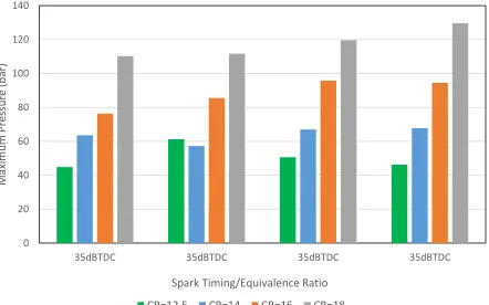
viii Figure 3.17 Comparison of maximum pressures for different spark ignition timing cases discussed above, at stoichiometric conditions. The cases in red are the
unfavorable conditions for the SACI combustion mode. ... 50 Figure 3.18 Pressure traces for spark timing 45dBTDC cases at the different equivalence ratios. ... 51 Figure 3.19 Pressure traces for spark timing 40dBTDC cases at the different equivalence ratios. ... 53 Figure 3.20 Pressure traces for spark timing 35dBTDC cases at the different equivalence ratios. ... 53
Figure 3.21 Comparison of maximum in-cylinder pressure for different equivalence
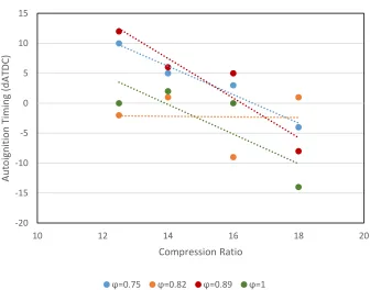
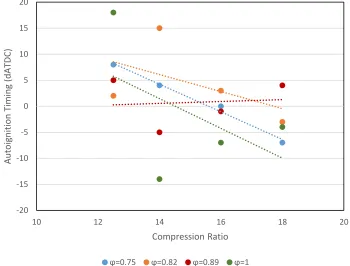
ratios at each case of spark timing ... 54 Figure 3.22 Plot of autoignition start timings vs. spark ignition timing for different
equivalence ratio cases. ... 55 Figure 3.23 Variation in max. pressure with compression ratio for the spark timing
cases at phi=0.75 ... 56 Figure 3.24 Variation in max. pressure with compression ratio for the spark timing
cases at phi=0.82 ... 57 Figure 3.25 Variation in max. pressure with compression ratio for the spark timing
cases at phi=0.89 ... 57 Figure 3.26 Variation in max. pressure with compression ratio for the spark timing
cases at phi=1 ... 58 Figure 3.27 Variation in max. pressure with compression ratio for changing
equivalence ratio cases at a spark timing of 45dBTDC ... 60 Figure 3.28 Variation in max. pressure with compression ratio for changing
equivalence ratio cases at a spark timing of 40dBTDC ... 60 Figure 3.29 Variation in max. pressure with compression ratio for changing
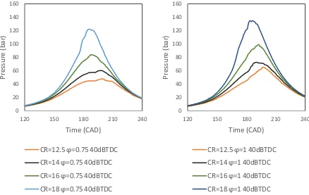
equivalence ratio cases at a spark timing of 35dBTDC ... 61 Figure 3.30 Pressure plots comparing CR cases at ϕ 0.75 and 1 for sparking at
40dBTDC. ... 62 Figure 3.31 Pressure plots comparing CR cases at ϕ 0.75 and 1 for sparking at
45dBTDC. ... 63 Figure 3.32 Pressure plots comparing CR cases at ϕ 0.75 and 1 for sparking at
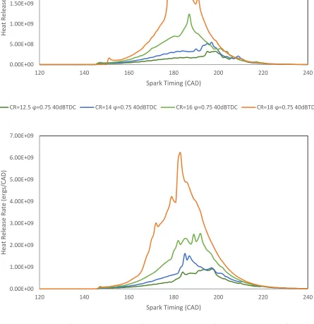
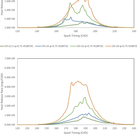
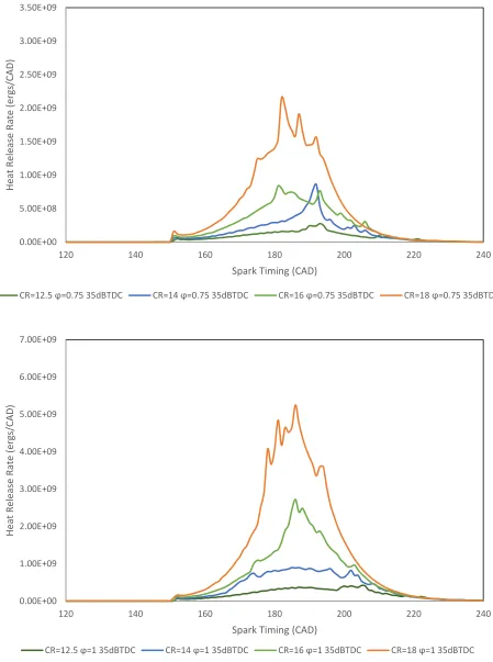
35dBTDC. ... 63 Figure 3.33 Heat release rate diagrams for sparking at 40dBTDC, and ϕ of 0.75 and 1,
for the different CR cases. ... 65 Figure 3.34 Heat release rate diagrams for sparking at 45dBTDC, and ϕ of 0.75 and 1,
for the different CR cases. ... 66 Figure 3.35 Heat release rate diagrams for sparking at 35dBTDC, and ϕ of 0.75 and 1,
ix
Figure 3.37 Autoignition points for cases of sparking at 40dBTDC ... 68
Figure 3.38 Autoignition points for cases of sparking at 35dBTDC ... 69
Figure 4.1 Pressure curves for the injection timing sweep cases, with a DI% of 30% ... 78
Figure 4.2 Heat release rate plot for injection at 130dBTDC, DI% 30% ... 79
Figure 4.3 Heat release rate plot (magnified) for injection at 120dBTDC, DI% 30% ... 79
Figure 4.4 Heat release rate plot for injection at 110dBTDC, DI% 30% ... 80
Figure 4.5 Heat release rate plot for injection at 100dBTDC, DI% 30% ... 80
Figure 4.6 Comparison of maximum pressure for each of the injection timing cases ... 82
Figure 4.7 Temperature plots over the normalized spatial domain, for the injection case of 110dBTDC, during the combustion events. ... 83
Figure 4.8 Temperature plots over the normalized spatial domain, for the injection case of 100dBTDC, during the combustion events. ... 84
Figure 4.9 Plot depicting autoignition timing vs. injection timing, for DI%=30% ... 86
Figure 4.10 Pressure plots for injection timing fixed at 130dBTDC, while DI% is varied ... 87
Figure 4.11 Heat release rate curves for the cases considered. Injection timing 130dBTDC, DI%=20%-60% ... 89
Figure 4.12 Pressure plots for injection timing fixed at 120dBTDC, while DI% is varied ... 90
Figure 4.13 Heat release rate curves for the cases considered. Injection timing 120dBTDC, DI%=20%-60% ... 91
Figure 4.14 Pressure plots for injection timing fixed at 110dBTDC, while DI% is varied ... 92
Figure 4.15 Heat release rate curves for the cases considered. Injection timing 110dBTDC, DI%=20%-60% ... 93
Figure 4.16 Pressure plots for injection timing fixed at 100dBTDC, while DI% is varied ... 94
Figure 4.17 Heat release rate curves for the cases considered. Injection timing 100dBTDC, DI%=20%-60% ... 95
Figure 4.18 Comparison of maximum in-cylinder pressure for different DI% values as injection timing is delayed ... 96
Figure 4.19 Plot showing autoignition points for different injection timing cases, comparing variation in DI% ... 97
Figure 4.20 Comparison between PFI and MPFI cases with injection timing 130dBTDC ... 98
Figure 4.21 Comparison of maximum pressure between PFI and MPFI cases ... 99
1
CHAPTER 1 INTRODUCTION
The requirement for better fuel economy, lower emissions and greater engine efficiency,
has led to the development of numerous innovations for the development of spark assisted (SI) and
compression ignition (CI) engines. Recent advances in internal combustion engines have increased
performance characteristics like volumetric, thermal and combustion efficiencies, harnessing
technologies such as turbochargers, superchargers, ECUs, common rail injection, sensors,
piezoelectric injectors, and many others. However, as we progress into the 21st century, the
restrictions and challenges for vehicles are increasing. In the past two decades there has been rapid
development in the field of advanced combustion engines, one of them being Spark Assisted
Compression Ignition (SACI) engine. This type of combustion engine design has displayed greater
production of in-cylinder pressure, temperature and heat release, compared to SI or CI engines,
due to its integration of higher compression ratios along with spark ignition. Research over the
years has made it possible to control gasoline combustion under increasingly adverse conditions
created by high compression ratios. This has been used to develop homogenous charge
compression ignition (HCCI) engines. This engine concept has been used to successfully increase
thermal efficiency [1,3] and reduce harmful emission like NOx [4]. However, it was also found
that the operating limits of HCCI are restricted to low to medium load conditions [5].
The SACI concept was first viewed as a bridging mechanism while transitioning from low
load HCCI combustion modes to high load SI mode in contemporary research [14-23] to propose
an engine concept suitable for different operating conditions. It was then developed as a
stand-alone engine concept and research was conducted to expand its operating limits from medium to
2 in the cylinder, stable combustion along with reduced emissions can be obtained. This type of
engine was first proposed and patented by Tanahashi et al. [6] and was later improved by Yang
[7]. The controlled combustion phasing combined with stable operation at medium to high load
capacity make SACI combustion concept a versatile method of power production, with higher
efficiency and reduced emissions. The SACI combustion mode is compatible with alternative fuels
such as ethanol [35], indolene and their combinations with conventional fuel sources.
Mazda is the first automotive manufacturer to take a step in this direction. The latest engine
designed by the company, called SKYACTIV-X, uses a combustion concept similar to the one
discussed in this study, called Spark Controlled Compression Ignition (SPCCI). It combines the
principles of SI and CI combustion, using a high compression ratio to pressurize the fuel-air
mixture and then using spark ignition to control the combustion phasing, in order to stabilize the
autoignition process. This concept is very similar to that of SACI.
1.1Spark Assisted Compression Ignition (SACI) combustion
The SACI combustion concept was developed as an improvement of the HCCI combustion
mode. It can be considered as a combination of the working principles of SI and CI engines, since
it employs a high compression ratio to pressurize the combustion charge while providing an energy
input via spark ignition to initiate a flame propagation phase, which stabilizes the autoignition of
the mixture. This allows more control on the heat released by combustion, compared to combustion
dependent solely on spontaneous autoignition of the air-fuel mixture within the chamber. The
spark timing can be varied to exercise control on flame propagation and autoignition phases of
combustion. This way heat released due to flame propagation and autoignition can be monitored
3 an engine. Port fuel injection allows greater homogeneity in the charge mixture, which can result
in stable combustion, by controlling the equivalence ratio of fuel. Direct injection may also be
used, for a more stratified fuel mixture, to promote combustion. To tackle the issue of instability
due to excessive input of heat energy at high pressure, charge dilution is generally preferred to
control the heat release from combustion reactions. This is achieved using either internal or
external exhaust gas recirculation (EGR) or a combination of both. Intake air temperature can be
controlled to induct preheated air into the combustion chamber, to promote the combustion
(autoignition) of the mixture.
The combustion process occurs in four stages: 1.) spark discharge; 2.) early kernel growth
(EKG); 3.) flame propagation; 4.) autoignition. A characteristic SACI combustion will exhibit
these stages, which can be analyzed through different methods like in-cylinder pressure plots, heat
release rate diagram and flame area growth. The different stages release heat energy, which can be
controlled with engine parameter variation. As the heat released during flame propagation is
higher, it increases the combustion chamber temperature. This leads to formation of NOx, which
can be controlled with charge dilution to prevent excessive heat release and control combustion
phasing. SACI allows greater distribution of heat release and lower overall peak heat release rate,
which results in a lower peak pressure rise rate (PPRR). The lower PPRR and the resulting lower
ringing intensity permits the addition of more fuel resulting in a higher load before ringing limits
4
1.2 HCCI Engines
A major concern is the emission of greenhouse gases like carbon monoxide, carbon
di-oxide, nitrogen oxides and particulate matter. Also, ensuring complete combustion and extracting
maximum power from the fuel charge is one of the primary motives of engine manufacturers. In
the past decades, various technologies have been researched to improve the combustion efficiency
of engines. Homogenous charge compression ignition (HCCI) is one of them, and currently
extensive research is being done to commercialize this technology. The major reason this
technology is attractive is its ability to provide a higher thermal efficiency compared to SI engines.
These improvements are made possible partly through unthrottled operation at low load, which
minimizes pumping loss. Thermal efficiency is also enhanced using a higher compression ratio to
promote auto-ignition. Combustion occurs at nearly constant volume (due to the fast burn rate of
the mixture), with greater expansion stroke work for a fraction of the fuel charge, provided by a
low-temperature lean mixture [1]. In HCCI engines, combustion phasing is thermally controlled
with intake temperature heating [2] or variable valve actuation to retain hot residual gases in the
combustion chamber [3]. The peak combustion temperatures are relatively low due to high charge
dilution with air or residual gas. These lower temperatures elevate the ratio of specific heat of the
mixture, which results in greater thermal efficiency. These low combustion temperatures greatly
reduce the NOx emissions from the engine, allowing it to meet emissions regulations without NOx
after-treatment [4]. It is possible to combust lean air-fuel mixtures by auto-ignition, which is not
possible in traditional SI engines. However, HCCI engines are not capable of operating at high
load conditions when naturally aspirated, achieving a maximum of about 4.0-5.0 bar IMEP [5].
Beyond this load condition, the operation becomes unstable due to excessive pressure rise rates,
5 control the combustion stability and ignition of the fuel, in order to control the pressure-rise rate
and temperature of combustion.
1.3 Literature Review
An improvement on the HCCI technology, a method of spark assisted compression ignition
(SACI) was proposed, where a spark is used to control the combustion. A patent by Tanahashi et
al. [6], proposes a spark-assist type self-ignition engine. An engine with a spark plug and an
injector in a combustion chamber, along with a sensor, which senses the gas temperature if it is at
a temperature close to auto-ignition. Depending on this a valve timing device controls the opening
time of the intake valve and maintains the gas temperature close to auto-ignition temperature,
which once achieved triggers the ignition of the spark plug. The objective of this combustion
system is to control the autoignition of the fuel to prevent knocking and prevention of NOx
formation. A subsequent patent proposed by Yang [7], identified disadvantages with the previous
proposal. At low engine load, SACI combustion generates higher levels of nitrous oxides and
results in lower fuel economy than what can be obtained from HCCI combustion. Also, at high
loads, without a degree of spark assist, the compression ignition combustion becomes ineffective
due to loss of accurate temperature control in the combustion chamber. Thus, an engine with dual
modes was proposed, wherein the first mode involves autoigniting the fuel-air mixture, and the
second mode involves assisting the combustion of the mixture with a spark. This was done to add
flexibility to the operating conditions of the engine at different load levels.
Four stages of SACI combustion were identified by Reuss et al. [8], namely, spark
discharge, early kernel growth, flame propagation and compression ignition. It was found that
6 kernel growth (EKG) stage. However, due to limitations in diagnostic methods, the effect of the
spark plasma in this stage could not be measured. This limitation was overcome in the study
conducted by Natarajan and Reuss, [9], and the first conclusion of the previous study was
confirmed. However, it was found that the spark ignition system did not affect the EKG cyclic
variations, but the charge composition distribution did. Pastor et al. [10], combined direct visual
diagnostic methods and spectroscopic analysis of natural radiation, with analysis of Rate of Heat
Release, to validate the works of Reuss [8,9]. The spectral analysis of the combustion reaction
radicals was used to study the progress of the combustion process and identify the transition of the
SACI stages. A similar research was conducted by Benajes et al. [11], for a gasoline partially
premixed spark assisted compression ignition engine at low load to better observe the combustion
process. It was found that, apart from spark assistance and ignition timing, the fuel injection timing
and duration had an important role in improving combustion stability, cyclic stability and
combustion phase duration. The author continued this work in [12] to show the effect on emissions
due to single and double direct fuel injection strategies, and by varying the fuel fraction in the
double injection case. It was concluded that air/fuel mixture distribution was improved using
double injection strategy and increased the fuel energy conversion efficiency.
In order to help understand the spark assisted process, a multi-mode combustion diagram
was proposed by Lavoie et al., [13] to delineate the regimes of ignition, flame propagation,
quenching and knocking, in HCCI, SACI and SI combustion in terms of unburned and burned gas
temperatures near top dead center. It relates constraints due to gas properties, as a function of
unburned gas properties, NOx limits and flame propagation. An analysis of existing experimental
data was used to suggest that the effectiveness of spark assisted compression ignition is best at
7 unable to sustain combustion in this mode. This diagram is useful to identify limiting reduced
equivalence ratios for each mode of combustion. The equivalence ratios were calculated as a
function of equivalence ratio of the combustion charge as well as the residual gas fraction (RGF).
Analysis of available experimental SACI data in terms of the MMCD, indicates that spark assist
is most useful for ignition and burn rate control under moderate to high loads where flame speed
is adequate.
Initially, sparking was used to make a transition from SI combustion to HCCI mode and to
increase the load capacity of the HCCI engine. Persson et al. [14], conducted experiments in this
effort. In this experiment, he used a modified gasoline engine, with a compression ratio for SI
combustion. Therefore, in this research work, different air intake temperatures, in conjunction with
various speed and load combinations, were used to study the response of the engine. It was noticed
that changing the intake temperature caused the combustion timing to vary accordingly. A very
low intake temperature leads to high emissions. Also, at high load conditions, which require richer
mixtures, dilution by EGR can be reduced and can be substituted by intake air heating instead, to
stabilize the combustion thereby minimizing misfires. Another research published by the same
author, [15], investigated the variations and correlations in the parametric outputs, in consecutive
cycles in each of the cylinders of a six-cylinder engine. The correlation coefficient used previously
by Christensen [16], was utilized to detect the periodic behavior on HCCI combustion. There was
not much correlation found between the cylinder operation, however, different engine load levels
and speeds affected the cyclic behavior of the cylinders. Spark assistance was found to increase
the operating regime as well as the efficiency of the HCCI combustion mode.
This technology was utilized by Wang et al. [17], to propose a method for transition
8 observed that combining two stage direct fuel injection and spark ignition enhanced control on
ignition and combustion rate of HCCI mode while extending its operating range. At HCCI critical
status, without sparking, the combustion becomes highly unstable due to knocking and misfire,
causing fluctuations in engine speed, which leads to retardation in ignition timing, causing
repetitive instabilities. This however was mitigated with spark ignition. There was a reported
increase of 39% in IMEP, and reduction in emissions, notably 74% in NOx emissions. The spark
ignition enhances the autoignition process in the combustion chamber, leading to a more uniform
and rapid heat release rate, although, visualizations from the optical engine showed minimal flame
propagation. This points to the fact that sparking plays an assistive role rather than a primary
combustion role. Hyvonen et al. [18], conducted an experiment on a Saab variable compression
ratio engine, with 5 cylinders. In this experiment, spark assisted HCCI was considered a particular
case and another case was considered for a mode change from HCCI to SI, with sparking for
combustion with flame propagation. It was found that with spark assistance the compression ratio
and inlet air temperatures required for combustion were lower compared to HCCI combustion, for
the same operating points. It should also be noted, that with the introduction of spark ignition,
cyclic variations resulting in combustion fluctuations, typical to SI engines, occur in dependence
with A/F variations.
To better understand the transition region between the SI and HCCI region, that is the SACI
region, Wagner et al. [19], created a series of probability maps to predict the combustion variations
by heat released at various levels of internal EGR. It was identified that cyclic variations occur in
combustion events, which are essentially a feedback effect of the recirculated exhaust gas. As a
part of this research, maps were created for each transition zone from conventional SI to HCCI
9 of combustion events occurring in the transition modes at different EGR levels. This pattern was
then compared to the predicted model of the combustion events and matched closely to the
non-linear prediction model. The model was created utilizing works done by Daw et al. [20-22], on
observing non-linear dynamics in a combustion engine. As a continuation of this work, Daw and
Wagner [23], conducted another investigation into the reaction kinetics of an engine in the
SI-HCCI transition combustion region. Through the analysis of data acquired from an engine
operating in these combustion modes, the researchers have created a predictive model for the cyclic
variations of different parameters. This shows that the kinetic parameters can be obtained from
successive cyclic combustion measurements.
The extensive work done by Wagner, Daw, Edwards and others, [19,24-28], on the
investigation of cyclic variability during transition from SI to HCCI combustion modes, was
further investigated by Havstad et al. [29]. A multi-zone combustion model was proposed to
compute combustion events in an economic computational time, as a compromise between high
fidelity engine modeling code, KIVA [30] and existing single zone models [31]. Although the
model presented was unable to analyze the complex reaction dynamics which result in the
instabilities in the combustion mode transitions, it could however predict patterns of instability
during the transition process. The author mentions improvements which could be implemented to
improve the fidelity of the model, to better predict information for stabilizing the spark assisted
HCCI combustion mode.
Persson et al. [32], conducted an experiment focusing on the effect of spark ignition, as
well as certain specific parameters, on combustion initiation and progress. The changes on this
phenomenon were studied by varying negative valve overlap, spark timing and load. A blend of
10 between isooctane and n-heptane. SACI has stable operation at high dilution percentage levels due
to the higher temperature of the residual mixture, which balances the heat losses from the spark
kernel, and makes combustion in the very lean mixture possible. Also, varying the spark timing
affects the onset of autoignition, advancing the sparking, advances the autoignition. Spark timing
also affects the initial flame propagation speed near the spark plug, which can advance or retard
the resulting autoignition of the remaining fuel mixture. Following this, Persson et al., investigated
the effect of induced swirling on SACI combustion [33]. The swirling of the intake charge was
induced by deactivating one of the intake valves on the engine in each scenario. This resulted in
an increase in turbulence in the combustion chamber, thereby accelerating combustion timing.
Using high percentage of EGR dilution in this scenario, however, results in delay in combustion
timing. This can be used for extending the HCCI operating region to lower loads and speeds.
A research conducted by Urushihara et al., [34], utilized the concept of spark assist in HCCI
combustion to extend its operating range. It was conducted experimentally in a single cylinder
engine with multipoint fuel injection. The data was obtained at 1200 and 2400 rpm, with a fraction
of the fuel injected directly, to obtain a stratified mixture near the plug, while the rest of it was
injected through port injection, to develop a homogeneous mixture in the combustion chamber. It
was observed that the SI-CI combustion has higher load capacity compared to HCCI mode, without
intake air heating. However, at low loads, as the intake air temperature rises, through spark and
injection timing retardation, stable combustion can be maintained. It was also found that
introducing internal EGR by Negative Valve Overlap(NVO), can lead to expansion of operating
range of the engine, as well as improve thermal efficiency. The earlier the NVO occurs, the more
stable the combustion is at lower loads. Persson et al., [35], carried out a similar research, using
11 valve, along with a DI in the cylinder, and cases were considered where one port was closed, to
induce turbulence in the combustion chamber [33]. Using only PFI, moderate stratification was
obtained, which increased as the percentage of fuel injected through DI was increased. However,
increased DI percentage lead to slight delay in combustion along with slightly reduced heat release
rates.
As per a research carried out by Laura et al., [36], the goal was to extend the high load limit
of an HCCI engine using SACI technology, while maintaining a stoichiometric equivalence ratio.
In-cylinder pressure rise rate and combustion stability were controlled using cooled external EGR,
spark assist and negative valve overlap. Using this strategy, a maximum engine load of around 7.5
bar NMEP was achieved while maintaining efficiency and complying with emission regulations.
This study showed that stable dilute, and efficient combustion could be achieved with SACI at
loads above the allowable limits for naturally-aspirated HCCI. Spark advance affects the
combustion time and heat release rates, increasing the efficiency and expansion work as the
combustion becomes more constant volume for a given fueling rate. Laura et al., [37], conducted
another research to show that burn duration and combustion phasing for SACI mode can be
controlled by varying spark timing and unburned temperature, while holding composition of the
cylinder charge constant.
Yun et al., [38], conducted a comprehensive investigation to extend the high load-operating
regime of HCCI combustion through spark ignition, to increase fuel economy and avoid knocking
and transitions in combustion modes. The method of negative valve overlap (NVO) was used to
keep the combustion stable at low load conditions [34,39-42]. It was observed that injection timing,
spark timing and higher EGR dilution were essential for efficient spark assisted HCCI combustion
12 found that with increase in engine load, NVO had to be decreased, which led to rise in ringing.
This was tackled by retarding spark timing, however, an increase in pumping losses was observed.
The authors conducted another study, [43], using positive valve overlap (PVO). Through this
method, ringing was relatively lower at high loads, due to lesser hot residuals in the cylinder and
more EGR dilution than NVO, and higher efficiency was achieved due to reduction in pumping
losses. The study by Xie et al., [44], is focused on the SACI combustion using positive valve
overlap (PVO) strategy to optimize the gasoline engine performance at medium–high load. Based
on the demand of iEGR and eEGR, an optimized PVO strategy is proposed, in which the PVO is
formed mainly by advancing intake valve timing and subordinately by retarding exhaust valve
timing. A stable SACI combustion is achieved in the range of 5–9 bar, with significant
improvements in fuel economy, pumping loss and NOx emission.
The study by J.B. Martz et al., [45], investigates the correlation of premixed isooctane-air
laminar reaction front data under the highly dilute, high preheat temperatures of SACI combustion.
HCT, a premixed transient laminar flame simulation, was used to produce reaction front data under
conditions pertinent to both SI and SACI combustion modes, extending on the previous works of
Metghalchi and Keck [46], and Müller et al., [47], which were based on conditions relevant to SI
combustion. The investigation focused on variation of equivalence ratio, unburned temperature
and pressure. This analysis suggested that SACI combustion is most useful at medium and high
engine loads. Data from the steady reaction front and constant pressure adiabatic flame
temperature calculations were used to produce correlations of laminar burning velocity, thickness
and adiabatic flame temperature. Another study conducted by Dahms et al. [48], focuses on similar
objectives but combines different simulation methods to demonstrate a mixed mode combustion
13 A DNS study was conducted by Yoo et al., [49], to demonstrate the combustion
characteristics of iso-octane/air mixture under HCCI and SACI combustion, under various extents
of temperature and turbulence fluctuations, and spark ignition timings. A 99-species reduced
mechanism for the iso-octane/air chemical kinetics was developed and validated against detailed
and skeletal models, using methods established by Mehl et.al, [50], Lu et al., [51-53]. The effects
of parameters such as thermal stratification of mixture, spark timing variation and turbulence
intensity were simulated. A two-dimensional (temporal and spatial) DNS solver [54] utilizing
detailed chemical kinetics mechanism of hydrogen fuel was also developed and studied.
Bhagatwala et al., [55], developed a two and three-dimensional DNS model for investigating HCCI
and SACI combustion. This model used compression heating through mass source/sink terms to
simulate the piston motion. The combustion characteristics were studied, with focus on simulating
the flame motion and combustion phasing process.
Ziegler et al., [56], conducted an experimental research on an optical engine, using
multi-axis imaging to better understand the combustion process in a SACI engine. Although, not many
parametric effects were considered in this paper, it was important in exhibiting the improvement
in visualization of the combustion phenomenon. The detailed images show the flame development
and propagation over the cycle and are helpful to realise the spark assist results in enhancement of
the autoignition of the fuel and heat release, due to an initial flame propagation, while accelerating
ignition time. Ziegler et al., [57], found the effects of intake air temperature variations on
spark-assisted HCCI combustion in a single cylinder research engine. It was found that the equivalence
ratio affected the performance of the combustion mode, however, thermal stratification is a crucial
factor in this mode. It was also concluded through imaging techniques that heat release rate data
14 Liu et al., [58], proposed a ‘controlled Assisted Spark Stratified Compression
ignition(ASSCI) with moderate autoignition’ combustion mode, to minimize knocking while
maintaining high thermal efficiency. After running different test conditions, the conditions best
identified for the setup was dual stage injection combined with 20% cooled external EGR. Using
a fixed high compression ratio and stoichiometric fuel conditions in a GDI engine, it was found
that combustion involved a two-stage heat release process. Also, with minimum spark advance
(knock-limit), using a diluted stoichiometric stratified fuel-air mixture can minimize knocking.
1.4 One Dimensional Turbulence (ODT)
Turbulent fluid flow is characterized by randomness and unsteadiness coupled with rapid
fluid mixing and simultaneous reactions. Such flows possess varied ranges of length and time
scales. Contemporary turbulence models separate large scale turbulent motion and small scale
molecular transport and chemical kinetics in length and time domains. It was found by Peters [60],
that for an extensive range of turbulent combustion cases, scale separation is not a valid aspect for
their modelling.
Kerstein developed the Linear Eddy Model (LEM) [61], a turbulence model to effectively
predict the mixing-reaction couplings at all scales. It spatially and temporally resolves, in a
one-dimensional domain, the processes of turbulent advection, scalar and momentum transport and
chemistry. The model simultaneously implements deterministic processes for the diffusive and
reactive terms of the governing equations and a stochastic method for the turbulent advection term.
This stochastic method applies ‘triplet map’ stirring events, which emulate the compressive strain
and rotational folding characteristics of turbulent eddies and arbitrarily select eddies of varying
15 The One-Dimensional Turbulence (ODT) model is an extension of the LEM model [63].
This model categorizes turbulent advection and molecular transport processes as distinct events on
a one-dimensional domain. The solution of the velocity vector in the ODT model, provides the
necessary details about the shear field, hence a way to drive the turbulence. Thus, it can be
concluded that this model is a self-sufficient turbulence model and can be used independently for
simple flow problems. This model has two main advantages. Firstly, this model can realistically
describe the physics while maintaining fine resolution like DNS. Secondly, this model provides
computational economy. The ODT model has been applied to various turbulence problems due to
its ability to resolve all temporal and length scales on a one-dimensional domain. Various ODT
model formulations have been used as stand-alone models [64,65,66] or as a sub-grid closure
model in hybrid multidimensional formulations like ODT/RANS [67] and ODT/LES [68,69].
As the ODT model is an independent turbulence model, it has been used to study the
in-cylinder turbulent interactions in a Spark Assisted Compression Ignition (SACI) engine, using
iso-octane as the fuel. As the chemical reaction mechanism for iso-iso-octane and air is complex, a primary
reference fuel with reduced chemistry is utilized, since it offers computational economy while
providing sufficient insight into the combustion chemistry characteristics under turbulent
16
1.5 Objective
This study conducts high resolution one-dimensional turbulence simulations of spark
assisted compression ignition (SACI) combustion to investigate this concept, using iso-octane as
a fuel. Numerical studies have been made using this ODT model, since it provides realistic
information regarding chemical interactions in unsteady flow conditions, while providing the
flexibility to study different engine parameters over a wide range. The aim is to investigate suitable
ranges of operating conditions for characteristic SACI combustion. The engine conditions, like
spark timing, equivalence ratio, compression ratio and fuel injection specifications, have been
varied over a wide range, for this purpose. The study was conducted to investigate SACI behavior
under two different fueling conditions: Port Fuel Injection (PFI) and a combination of PFI and
direct injection (DI), termed as Multipoint Fuel Injection(MPFI), to observe the effect of fuel
stratification on combustion.
1.6 Overview
This study first introduces the concept of SACI combustion, and reviews the previous
works done on this concept as well as the ODT model. Then the model formulation is discussed,
including domain specification, the governing equations used and their boundary conditions for
this model, followed by a brief discussion of their numerical implementation in this model. After
that the observations made for varying different parameters in PFI mode of fuel injection are
discussed. This is followed by discussion of results of MPFI strategy of fuel injection. Finally, the
major conclusions from this study are presented, along with possible areas which can be further
17
CHAPTER 2 NUMERICAL SETUP
This section discusses the formulation of the model used in this study of turbulent
combustion of iso-octane air mixture in a spark assisted compression ignition (SACI), single
cylinder engine. The model formulation is based on previous ODT models designed by Gowda
and Echekki [70], and Echekki et al. [71]. The major difference between the previous studies and
the current one is that an additional source term is added in the energy equation, which emulates
spark ignition, activating at the time specified for the various simulation cases, in order to
implement spark assistance for the HCCI model developed by Echekki and Gowda.
To realistically model the numerous interactions occurring in the combustion chamber
during the compression and power strokes in a SACI engine, the fluid is assumed to possess
variable density incompressible flow. This means that the flow always has a sufficiently low Mach
number to function in incompressible conditions, but the density is allowed to vary to simulate the
compression and expansion of the gases in the chamber due to piston movement and heat release.
This model does not consider axial variations in velocity, concentration and temperature as
discussed in the next section. The governing equations of fluid mechanics are used to calculate
thermo-physical properties like density and velocity, which are dependent on the changes in
domain length, temperature, pressure and molar concentration changes.
The momentum balance equation is used to calculate the radial variations of fluid velocity,
which is dependent on changes in temperature and value of moles due to the various reactions. The
species conservation equation is used to calculate molar species concentration change. The energy
conservation equation is also used in the model to compute the temperature variations in the
18 simplify the other governing equations. Additional equations, like the ideal gas equation of state
and overall system mass conservation equation, are applied to compute the density and the
in-cylinder pressure at every iteration.
This chapter discusses the domain selection, the assumptions made, the derivation of the
governing reaction-diffusion equation, and the details of its implementation as a stand-alone ODT
model for SACI mode combustion simulations.
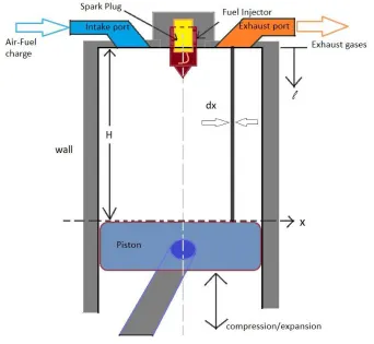
2.1 Domain Specification
In this model the domain for the one-dimensional space is chosen along the lateral direction
(x). This domain is assumed to be located on the piston head and is perpendicular to piston
movement. The domain is divided into a number of differential elements, each of uniform length
(dx), dependent on the domain size specified and the resolution required. These elements are
modeled to possess uniform properties in the axial direction, while maintaining equal
cross-sectional area. The area of cross section (Acs) and length of differential elements (dx) are kept
constant for the duration of the simulation. To account for volumetric change of the combustion
chamber in the axial direction, for the compression and expansion strokes, the variation is modeled
by implementing and updating the stroke length, ℓ, with every iteration, which is defined in the
axial direction as well. This method of domain specification of the combustion chamber,
represented in the Fig. 2.1 simplifies the modeling of the in-cylinder fluid flow as well as the
implementation of fuel injection and moving boundary, while enabling the realistic
implementation of the same. Fuel injection is realized by updating the fuel composition of the
differential element (dx) which is located at the position where fuel injection is specified. This
19 reasonable approximation, since the length scales of individual elements (dx) and actual nozzle
diameters are similar in order of magnitude. The injection occurs over the duration specified, such
that at the end of the injection event the fuel-air mass ratio in the cylinder is equal to the required
value of equivalence ratio.
20
2.2 Assumptions
• The total mass of the system remains constant through the compression and expansion
strokes of the engine. It is assumed that IVC takes place before the compression stroke
begins, i.e. start of simulation, while EVO occurs after the expansion stroke is complete,
i.e. end of simulation. This prevents mass change in the combustion chamber during the
simulation.
• The in-cylinder mixture contains no particulate matter (PM) and is composed of gases at
all times.
• The in-cylinder gaseous mixture is an ideal gas. It is assumed that for the pressure and
volume ranges encountered in an engine, the deviation from ideal gas behavior is
negligible for the mixture.
• The cylinder has a uniform bore and a flat piston geometry.
• Variable-density incompressible flow is assumed, and the in-cylinder pressure is assumed
to be uniform.
• The gas mixture is modeled as a Newtonian fluid.
• Heat flux due to Dufour effect is neglected.
• It is assumed that there is no heat transfer in the axial direction, in the combustion
chamber. The cylinder head and piston surfaces are assumed to be adiabatic, while the
wall is modeled as heat sink with a fixed temperature.
• Mixing is dominated by spray injection due to which reaction and diffusion components
21
2.3 Momentum Conservation
The momentum conservation equation is applied over the differential length (dx), to find
the velocity of the fluid flow.
𝜕𝑢
𝜕𝑡 =
1 𝜌
𝜕
𝜕𝑥(𝜇
𝜕𝑢
𝜕𝑥) + Ω𝑢
The above equation is used as the governing equation for momentum conservation for this model.
The boundary conditions: 𝑢(𝑡, −𝐿
2) = 𝑢𝑙𝑒𝑓𝑡(𝑡) & 𝑢(𝑡, 𝐿
2) = 𝑢𝑟𝑖𝑔ℎ𝑡(𝑡) , 𝑓𝑜𝑟 𝑎𝑙𝑙 𝑡 > 0
2.4 Species Mass Conservation
The species mass conservation equation used in the model is as shown below,
𝜕𝑌𝑘
𝜕𝑡 = −
1 𝜌
𝜕
𝜕𝑥(𝜌𝑌𝑘𝑉𝑘) + 1
𝜌𝜔̇𝑘+ Ω𝑘
𝑌𝑘 is the species mass fraction, defined by 𝜌𝑘 = 𝜌𝑌𝑘.
The boundary conditions: [𝜕𝑌𝑘
𝜕𝑥]𝑥=−𝐿 2⁄ = 0 & [ 𝜕𝑌𝑘
22
2.5 Energy Conservation
The equation for conservation of energy is given below,
(𝜕𝑇 𝜕𝑡) =
1 𝜌𝐶̅̅̅𝑝
𝜕
𝜕𝑥(𝜆
𝜕𝑇 𝜕𝑥) −
1 𝜌𝐶̅̅̅𝑝∑
𝜕
𝜕𝑥(𝜌𝑘𝑉𝑘𝐶𝑝,𝑘𝑇) 𝑁
𝑘=1
− 1
𝜌𝐶̅̅̅𝑝∑(ℎ𝑘𝜔̇𝑘) 𝑁
𝑘=1
− 𝑃̅̅̅𝑇 𝜌𝐶𝑝
[𝑑𝑙 𝑑𝑡]𝑏𝑑𝑟𝑦
+ Ω𝑇
The walls operate under constant temperature conditions, as required for the simulation
case. For constant temperature conditions (emulate external cooling), Dirichlet boundary
conditions are applied which are defined as follows,
Dirichlet boundary
conditions:
𝑇(𝑡, −𝐿
2) = 𝑇𝑤𝑎𝑙𝑙 & 𝑇(𝑡, 𝐿
2) = 𝑇𝑤𝑎𝑙𝑙 , 𝑓𝑜𝑟 𝑎𝑙𝑙 𝑡 > 0
2.6 Constitutive Relations 2.6.1 Thermodynamic Pressure
The ideal gas law expresses the pressure of a gaseous mixture as a function of its density
and temperature.
The volume of the combustion chamber changes with time due to piston movement. The
ideal gas law, however needs to be satisfied at every instance of time. This is achieved by applying
a volume mean. Another aspect is that the overall mixture density used in the relation is calculated
by mass conservation in the total volume of the chamber, as it is assumed that the valves are closed
during the simulation, therefore there is no mass exchange throughout the cycle. The density is
23
𝜌 =𝑚𝑡𝑜𝑡𝑎𝑙 𝑉𝑡𝑜𝑡𝑎𝑙
where 𝑚𝑡𝑜𝑡𝑎𝑙 is calculated using initial values of density and volume, 𝑚𝑡𝑜𝑡𝑎𝑙 = 𝑚0 = 𝜌0𝑉0.
The in-cylinder thermodynamic pressure is formulated as follows,
𝑃𝑇 = 〈 𝜌𝑅𝑢𝑇
𝑀 〉 =
∫ 𝐴𝑐𝑠( 𝜌𝑅𝑢𝑇
𝑀 ) 𝑑𝑥 𝑉𝑡𝑜𝑡𝑎𝑙
2.6.2 Piston Speed
In this model, the origin is considered to be located at the cylinder head and the top dead
center (TDC) as the reference point. If𝑉𝑐 is the clearance volume, 𝐴𝑐𝑠 the bore, 𝑙𝑟𝑜𝑑 the length of
the connecting rod, ‘a’ the crank radius and 𝑙𝑏𝑑𝑟𝑦 the instantaneous distance between the crank
axis and piston axis, the instantaneous total volume of the combustion chamber can be written as,
𝑉𝑡𝑜𝑡𝑎𝑙 = 𝑉𝑐+ 𝐴𝑐𝑠(𝑙𝑟𝑜𝑑 + 𝑎 − 𝑙𝑏𝑑𝑟𝑦)
The instantaneous distance between piston pin and crank axes, can be calculated by
considering the system as a slider-crank mechanism [72].
𝑙𝑏𝑑𝑟𝑦 = 𝑎 𝑐𝑜𝑠(𝜔𝑡) + (𝑙𝑟𝑜𝑑2− 𝑎2(𝑠𝑖𝑛(𝜔𝑡))2) 1 2⁄
24 Also, the following have been defined to establish engine geometry,
𝐻𝑠𝑡𝑟𝑜𝑘𝑒 = 2𝑎
𝑆𝑝
̅̅̅ = 2𝑁𝐻𝑠𝑡𝑟𝑜𝑘𝑒
𝑅 =𝑙𝑟𝑜𝑑 𝑎
By differentiating the instantaneous boundary length with respect to time, and applying
the above relations, an expression for piston speed as a function of time is obtained.
[𝑑𝑙
𝑑𝑡]𝑏𝑑𝑟𝑦 = − 𝜋
2𝑆̅̅̅ 𝑠𝑖𝑛(𝜔𝑡) [1 +𝑝
𝑐𝑜𝑠(𝜔𝑡)
(𝑅2− (𝑠𝑖𝑛(𝜔𝑡))2)1 2⁄ ]
Here the negative sign on the RHS is because of the simulation beginning from bottom
25
2.7 Summary of the ODT Model Equations
The ODT model equations discussed above have been summarized in Fig. 2.2. To account
for turbulent advection, a stochastic term (Ω) is added to each of the deterministic equations. The
numerical implementation of this stochastic term has been discussed in Section 2.8.
Momentum Conservation 𝜕𝑢 𝜕𝑡 = 1 𝜌 𝜕 𝜕𝑥(𝜇 𝜕𝑢 𝜕𝑥) + Ω𝑢
Boundary conditions 𝑢(𝑡, −𝐿
2) = 𝑢𝑙𝑒𝑓𝑡(𝑡) & 𝑢(𝑡, 𝐿
2) = 𝑢𝑟𝑖𝑔ℎ𝑡(𝑡) , 𝑓𝑜𝑟 𝑎𝑙𝑙 𝑡 > 0
Species Conservation 𝜕𝑌𝑘
𝜕𝑡 = − 1 𝜌 𝜕 𝜕𝑥(𝜌𝑌𝑘𝑉𝑘) + 1 𝜌𝜔̇𝑘+ Ω𝑘
Boundary conditions [𝜕𝑌𝑘
𝜕𝑥]𝑥=−𝐿 2⁄
= 0 & [𝜕𝑌𝑘 𝜕𝑥]𝑥=𝐿 2⁄
= 0 𝑓𝑜𝑟 𝑎𝑙𝑙 𝑡 > 0
Energy (𝜕𝑇 𝜕𝑡) = 1 𝜌𝐶̅̅̅𝑝 𝜕 𝜕𝑥(𝜆 𝜕𝑇 𝜕𝑥) − 1 𝜌𝐶̅̅̅𝑝∑ 𝜕 𝜕𝑥(𝜌𝑘𝑉𝑘𝐶𝑝,𝑘𝑇) 𝑁 𝑘=1 − 1 𝜌𝐶̅̅̅𝑝∑(ℎ𝑘𝜔̇𝑘) 𝑁 𝑘=1 − 𝑃̅̅̅𝑇 𝜌𝐶𝑝 [𝑑𝑙 𝑑𝑡]𝑏𝑑𝑟𝑦 + Ω𝑇
Boundary conditions 𝑇(𝑡, −
𝐿
2) = 𝑇𝑤𝑎𝑙𝑙 & 𝑇(𝑡, 𝐿
2) = 𝑇𝑤𝑎𝑙𝑙 𝑓𝑜𝑟 𝑎𝑙𝑙 𝑡 > 0 (𝐼𝑠𝑜𝑡ℎ𝑒𝑟𝑚𝑎𝑙 𝑤𝑎𝑙𝑙)
Additional Equations 𝑃𝑇 = 〈𝜌𝑅𝑢𝑇 𝑀 〉 = ∫ (𝜌𝑅𝑀 ) 𝑑𝑥𝑢𝑇 ∫ 𝑑𝑥 [𝑑𝑙 𝑑𝑡]𝑏𝑑𝑟𝑦 = − 𝜋
2𝑆̅̅̅ 𝑠𝑖𝑛(𝜔𝑡) [1 +𝑝
𝑐𝑜𝑠(𝜔𝑡)
(𝑅2− (𝑠𝑖𝑛(𝜔𝑡))2)1 2⁄ ]
𝜌 =𝜌0(𝑉𝑐+ 𝐴𝑐𝑠𝐻) ∫ 𝐴𝑐𝑠𝑑𝑥
26
2.8 Numerical Implementation
The one-dimensional turbulence (ODT) model implements the unsteady governing
equations, summarized in the previous Section 2.7, numerically. It does so by dividing the terms
into two categories. The diffusive terms are computed deterministically using a central difference
scheme to update the 1-D spatial profile. Temporal discretization of the governing equations is
attained by splitting the diffusion and reaction terms. Diffusion progress is achieved using
first-order forward Euler method, while the source term is calculated using DVODE, a stiff-integrator
[73]. Mixture-averaged transport properties for heat and mass transfer are computed using
transport libraries [74] that are provided within the CHEMKIN II suite [75].
Turbulent advection is implemented stochastically, achieved through the application of a
‘triplet map’ for each stirring event [62,71]. These maps replicate the compressive strain and
rotational folding effects that are characteristic of eddy events. Eddy segments are randomly
selected with a boundary located at 𝐱̂, 𝑎𝑛𝑑 𝑠𝑖𝑧𝑒 𝐥̂, so that an eddy of length span ⌊𝐱̂, 𝐱̂ + 𝐥̂⌋ is
selected for application of the triplet map in the one-dimensional scalar field. A conservative
rearrangement is performed by replacing the selected profile of segment length, 𝐥̂, with three
duplicate profiles compressed to a third of their original length. The middle copy is then inverted
to maintain continuity in values obtained in the new profile. The derivatives at the interfaces of
the three duplicate profiles, however, are not continuous.
The velocity component of the scalar field in the domain space is used to calculate the rate
of shear, which in turn provides a method of modulating the location and frequency of the stirring
events. The frequency is governed by an ‘eddy rate distribution’ which is calculated using a select
time scale with every transport event occurring at a given instant. This method of selection of
27 This model also has two parameters A and β, which are of order unity [71], and have magnitudes
similar to those used in an earlier work, which studied ODT simulation of auto-ignition in turbulent
jets [77]. The parameter, A, is a function of eddy characteristic time and the inverse of the rate of
shear applied at the selected eddy. The parameter, β, is a relation of eddy characteristic time and
elapsed temporal evolution of the domain. The purpose of this parameter is to prevent the selection
of triplet maps which have longer characteristic times than elapsed simulation time, thus allowing
stirring events to have progressively growing eddy sizes.
This study is conducted using a primary reference fuel (PRF), with a 171-species skeletal
kinetic mechanism, for Iso-octane (C8H18)-Air chemistry [78], based on the detailed mechanism
developed by Lawrence Livermore National Laboratory (LLNL) [79,80], which consists of 874
species and 3796 elementary reactions. The skeletal mechanism consists of 171 species and 861
reactions. The model has the flexibility to vary different parameters, in order to study the effect of
their variations, independently or in combinations, on the SACI combustion mode. Table 2.1 lists
the common parameters considered in this study along with their values or range of values. The
specific setup and run conditions for different problem sets have been discussed in the subsequent
chapters along with the results of their variations. The simulation runs were performed on DELL
workstations, utilizing a 64bit Windows operating system, equipped with Intel Core i7 2.4 GHz
processor and 16GB RAM. The simulations are made over 360 crank angle degrees (CAD), from
beginning of compression stroke to the end of expansion stroke, with a computation time of 16 to
28
Table 2.1: List of parameters used in the study of SACI combustion and their values or ranges
Fixed Parameters Value/ Range Units
Stroke length (H) 8.2 cm
Cylinder Bore (L) 8.0 cm
Compression ratio 12.5-18 -
Rod fraction (R) 2.0 -
Engine speed 2000 Rev/min
Port Injection velocity 1000 cm/s
Direct Injection velocity 1000 cm/s
Wall temperature 380 (107) K (℃), isothermal
Intake Pressure 1.0 bar
Intake charge temperature 500 K
Equivalence ratio 0.75-1.0 -
Spark timing (dBTDC) 50-20 -
Oxidizer temperature 500 (227) K (℃)
Fuel Temperature (at
29
CHAPTER 3
PORT FUEL INJECTION 3.1 Motivation
The aim is to study the behavior of SACI operation using isooctane as a fuel, without the
utilization of EGR. Experimental investigations conducted previously, utilize engines modified to
operate in SACI mode, with port fuel injection (PFI), direct injection or a multipoint fuel injection
strategy with direct injection and port fuel injection. This chapter investigates the range of SACI
combustion, the effect on combustion phasing and the characteristic results observed due to
changes in equivalence ratio through port fuel injection, spark timing and compression ratio. The
multipoint fuel injection strategy is studied in the following chapter. These two methods were
chosen to observe the differences due to charge homogenization and fuel stratification.
3.2 Run Conditions
The simulations were done under two different modes of fuel injection. First, port fuel
injection was investigated and then a combination of direct and port fuel injections. To compare
these two modes of injection, other engine parameters such as the compression ratio, the cylinder
dimensions, the intake velocity of fuel/ air charge, and the engine speed were kept constant. To
study the chemical behavior of the fuel, equivalence ratio, spark timing and compression ratio were
varied. The combustion cylinder wall is an isothermal boundary with a fixed temperature during
the combustion cycle. An elevated intake charge temperature is used to substitute the effect of
exhaust gas recirculation and to ensure that the fuels are injected in gas phase. It is assumed that
for a port fuel injection the fuel/air charge forms a homogenous mixture by the end of the intake
30 The simulation takes place from the beginning of the compression stroke (180 dBTDC)
and ends at the end of the expansion stroke (180 dATDC). The domain size (bore) is from -4 to +4
cm, i.e. 8 cm bore size. It is divided into 201 discretized grid points, giving a resolution of 0.4 mm.
Compression and expansion of the domain length is performed by applying the function for piston
speed. The change in length (stroke) is applied only to the work term for cylinder boundary in the
governing equations. The other transport and source terms are executed with a constant domain
with a resolution as specified above. The extent of change in the length is governed by the
compression ratio and the engine speed. Temperature changes of the in-cylinder mixture occurs
due to the compression and expansion of the domain.
To simulate PFI, some assumptions are made. The fuel/air charge is injected well before
the intake valve closes (IVC), and compression begins, such that, a homogenous mixture is
assumed to be formed at the beginning of compression stroke. The spark, modelled as a high
energy input at the centre of the 1D domain for a fraction of the domain width (bore), is activated
31
Table 3.1: Fixed parameters of the engine for the different run conditions
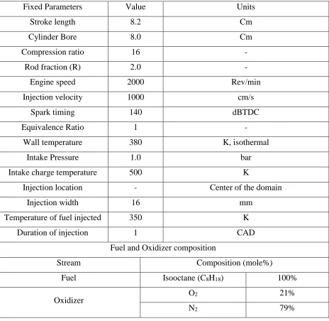
Fixed Parameters Value Units
Stroke length 8.2 cm
Cylinder Bore 8.0 cm
Compression ratio 12.5 -
Rod fraction (R) 2.0 -
Engine speed 2000 Rev/min
Injection velocity 1000 cm/s
Wall temperature 380 K, isothermal
Intake Pressure 1.0 bar
Intake charge temperature 500 K
Fuel and Oxidizer composition
Stream Composition (mole%)
Fuel Isooctane (C8H18) 100%
Oxidizer
O2 21%
N2 79%
Table 3.2 below summarizes the cases, which are considered for the PFI parametric study.
The equivalence ratio is varied over four values, for different spark timings. Then, the
corresponding cases are analysed to obtain suitable ranges of equivalence ratios and spark timings.
Table 3.2: PFI run conditions
PFI run conditions
Equivalence ratio 0.75, 0.82, 0.89, 1
32
3.3 Results and Discussions
3.3.1 Spark Timing Sweep
Figure 3.1: Plot showing the pressure curves for isooctane under SACI combustion at stoichiometric condition (FA=0.067) with different ignition timings.
Figure 3.1 shows the variation in the in-cylinder pressure due to changing ignition timing.
The legends denote the different spark timings for which the curves have been plotted. Also shown
with dashed lines is the pressure curve corresponding to motoring (i.e. no chemistry). A trend is
observed as the spark timing is advanced. At 35dBTDC spark timing, the maximum pressure is
around 46 bar, which is lower than the other curves. With spark advance, the maximum pressure
rises and then falls, with the curve for 40dBTDC spark timing exhibiting the largest in-cylinder
pressure of about 65 bar. The ignition of the charge in all cases is almost immediate, as seen in
0 10 20 30 40 50 60 70
120 140 160 180 200 220 240
Pres
su
re
(b
ar
)
Time (CAD)