Automobile to Minimize the Deteriorating
Effects
Amir Hussain Idrisi
1, Gaurang Deep
2, Vijay Sharma
3Assistant Professor, Department of Mechanical Engineering, SRMS CET, Bareilly, UP, India1 ,2 ,3
ABSTRACT: Clutch is the most important component of any automotive machine. It is a mechanism which is used to
transmitting the rotation from one shaft to another shaft by engagement and disengagement of the same. It is a connection between engine and transmission system which transmit power in the form of torque from engine to the gear assembly. When vehicle is in motion clutch is first disengaged for the drive to allow for gear selection and then again engaged smoothly to power the vehicle to transfer torque to the driving wheels.
In the present work SolidWorks software is used for modelling of two different types centrifugal clutch and ANSYS 14 workbench for static analysis then comparison is made for the maximum principle stress developed and maximum deflection in the three shoe clutch and rigid body type clutch which can be used in automotive vehicles.
KEYWORDS: Centrifugal Clutch, FEM, Solid works, Ansys workbench.
I. INTRODUCTION
Clutch
A clutch is a machine member used to connect a driving shaft to a driven shaft so that the driven shaft may be started or stopped without stopping the driving shaft. It is generally seen in automobiles. A little consideration will show that in order to change gears or to stop the vehicle, the driven shaft should not be connected with the energy source, but at the same time the engine should continue to run so it becomes necessary that the driven shaft should be disengaged from the driving
shaft. The engagement and disengagement of the shafts is obtained by means of a clutch which is operated by a lever.
Types of Clutches
Following are the two main types of clutches commonly used in engineering practice : 1. Positive clutches
2. Friction clutches
Positive Clutches
Square jaw clutch (b) spiral jaw clutch
Fig.1 Jaw clutches
Friction Clutches
A friction clutch has its application in the transmission of power of shafts and machine parts which must be started and stopped frequently. It is likewise utilized when force is to be conveyed to machines which is partially or fully loaded. The frictional force is utilized to begin the driven shaft from rest and gradually brings it up to the proper speed without excessive slipping of the friction surfaces. In automobiles, friction clutch is utilized to interface the engine to the drive shaft. In operation consideration ought to be taken so that the friction surfaces engage easily and gradually bring the driven shaft up to appropriate speed. The proper alignment of the bearing must be maintained and it should be located as close to the clutch as possible. It likewise be noticed that:
1. The contact surfaces should develop a frictional force that may pick up and hold the load with reasonably low pressure between the contact surfaces.
2. The heat of friction should be rapidly dissipated and tendency to grab should be at a minimum.
3. The surfaces should be backed by a material stiff enough to ensure a reasonably uniform distribution of pressure.
Considerations in Designing a Friction Clutch
The following considerations must be kept in mind while designing a friction clutch. 1. The suitable material forming the contact surfaces required to be chosen.
2. The moving parts of the clutch should have low weight in order to minimise the inertia load, especially in high speed service.
3. The clutch should not require any external force to maintain contact of the friction surfaces. 4. The provision for taking up wear of the contact surfaces must be provided.
5. The clutch should have provision for facilitating repairs.
6. The clutch should have provision for carrying away the heat generated at the contact surfaces.
7. The projecting parts of the clutch should be covered by guard.
Types of Friction Clutches
Though there are many types of friction clutches, yet the following are important from the subject point of view :
1. Disc or plate clutches (single disc or multiple disc clutch), 2. Cone clutches, and
3. Centrifugal clutches.
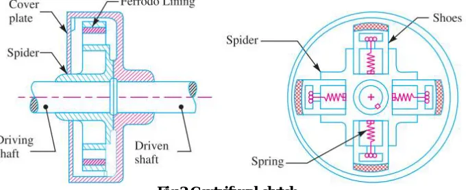
Centrifugal Clutch
Fig.2 Centrifugal clutch
II. OBJECTIVE OF WORK
Following are the major objectives of the given work
i) Firstly, to facilitate an automatic transmission system, which must has high strength and low deformation as compared to existing system.
ii) Secondly, to introduce light-weight vehicle transmission system where the transmission belt and pulleys are substituted with a centrifugal clutch and planetary gear assembly which is more compact and which avoid loss of power when operating at high speed.
iii) Lastly, to provide an automatic transmission which is light in weight, compact and economical of manufacturing.
III. MODELLING OF CENTRIFUGAL CLUTCH
In this section the modelling of Centrifugal clutch is done by SolidWorks modelling software. SolidWorks enables to design models as solids in progressive 3D solids modelling environment. Solid models are geometric models that offer mass properties such as volume, surface area and inertia.
Fig.3 Model of Rigid body type
Fig.4 Model of Three shoe clutch
IV. ANALYSIS OF CENRIFUGAL CLUTCH
The ANSYS software is a handy tool that has the capability to decide the type of elements that are required for the analysis purpose. The Finite Element Method is a mathematical tool used to compute ordinary equations and partial differential equations. Since it is a numerical tool, it has the ability to solve the complex problems that are represented in differential equations form. Mesh generation is one of the most critical aspects of engineering simulation. Too many cells may result in long solver runs, and too few may lead to inaccurate results. ANSYS Meshing technology provides a means to balance these requirements and obtain the right mesh for each simulation in the most automated way possible. ANSYS
Meshing technology has been built on the strengths of stand-alone, class-leading meshing tools. The strongest aspects of these separate tools have been brought together in a single environment to produce some of the most powerful meshing available. This helps in automatic choosing of elements and nodes and thus simplifies the job of FEM model creation. The meshing is performed by opening the ANSYS meshing application in workbench environment wherein the sizes of the elements are controlled.
Fig. 5 Three shoe clutch model imported in Ansys for analysis
V. RESULTS AND DISCUSSION
a) Maximum Principle stress
Fig. 7 Maximum Principle stress of three shoe clutch
Fig. 8 Maximum Principle stress of Rigid body type clutch
Fig. 9 Total deformation of Three shoe clutch
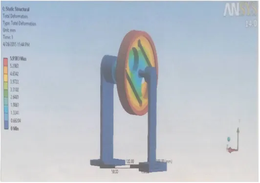
Fig. 10 Total deformation of Rigid body type clutch
Fig. 9 and fig. 10 shows maximum Deformation as 0.33029 mm and 5.9583 mm for three shoe cutch and rigid body type clutch respectively.
VI. CONCLUSION
It can be concluded from the result that the stress generated and deformation in three shoes clutch is less as compared to rigid type clutch system.
Table: Comparison between three shoe clutch and rigid body type clutch.
Type Three shoes clutch Rigid body type
clutch
Analysis also expressed the location of maximum deformation which is at clutch drum for three shoe clutch and bearing support for rigid body type clutch.
REFERENCES
[1] K.S.Aravindh et. fem analysis of wet multi plate clutch by varying friction surface material international research journal of engineering and technology (irjet) volume: 02 issue: 06 | sep-2015
[2] Prof. Nitinchandra r. patel et. design of centrifugal clutch by alternative approaches used in different applications international journal of innovative research in science, engineering and technology Vol. 1, Issue IV, April 2013
[3] Ananthasuresh, G.K., and Kota, “Designing Compliant Mechanisms”, Mechanical Engineering, Vol. 117, No.11, pp. 93-96.
[4] Karanjkar A. S et all, “Modelling and Simulation of Multi-Drive Clutch”, International Journal of Recent Development in Engineering and Technology, Volume 4, Issue 4, April 2015)
[5] B.Sreevani , M.Murali Mohan, “Static and Dynamic Analysis of Single Plate Clutch”, International Journal of Innovative Research in Science, Engineering and Technology, Vol. 4, Issue 9, September 2015
[6] Karan sehgal, Anuj pratap, and Ravi kuhar,. “CENTRIFUGAL CLUTCH DESIGN FOR VARIOUS APPLICATIONS”, IJRDO-Journal Of Mechanical And Civil Engineering, Vol. 1, Issue-5 May, 2015.
[7] Namrata Ashok Narkhede1 , Dheeraj Varma, “MODELLING AND ANALYSIS OF SINGLE CIRCULAR GROOVES MADE ON DRY FRICTION CLUTCHES”, International Journal of Research in Engineering and Technology, Vol. 5 Issue 8, Aug-2016.
[8] A.Rama Krishna Reddy, Dr.P.H.V.Sesha Talpa Sai, Dr. Mangeelal, “Design Modelling and Analysis of a Single Plate Clutch”, International Journal & Magazine of Engineering, Technology, Management and Research, Vol. 2, Issue 8, August 2015.
[9] Ganesh Raut, Anil Manjare, P Bhaskar “Analysis of Multidisc Clutch Using FEA” International Journal of Engineering Trends and Technology (IJETT) – Volume 6, issue 1, Dec 2013.
[10] Achi, P. B. U, “Design and Testing of an Automatic Clutch”, Sadhana, Vol. 9, No.3, pp 23-238.
[11] May Thin Gyan , Hla Min Htun , Htay Htay Win, “Design and Structural Analysis of Single Plate Clutch”, International journal of scientific engineering and technology research, ISSN 2319-8885, Vol. 03, Issue.10 May-2014, Pages:2238-2241.
[12] Abhijit Devaraj, “Design optimization of a kevlar 29 single disk friction clutch plate based on static analysis using ansys”, International journal of engineering sciences & research technology, vol. 4, issue 8, August, 2015.
[13] P.Naga Karna, Tippa Bhimasankara Rao, “Analysis of Friction Clutch plate using FEA”, International Journal of Engineering Research and Development, vol. 6, issue 2, pp 81-87, March 2013.