Single Stage Single Switch LED Driver with
Improved Power Factor Correction and Soft
Switching
Hasna V K 1, R. Gowtham Kumar 2
P.G. Student, Department ofElectrical & Electronics Engg, Maharaja Institute of Technology, Coimbatore, India1
Asst. Professor, Department ofElectrical & Electronics Engg, Maharaja Institute of Technology, Coimbatore, India2
ABSTRACT: Light Emitting Diodes (LEDs) with their current performances have been proved to be the most suitable solution for street lighting applications. Nowadays, a topic of interest in this context is the design for electronic driver in order to take the advantage of LEDs performances. However, requirements such as high power factor, long life time, accurate current control and high efficiency pose challenges to the design of LED driver circuits. A novel high-power-factor single-stage single-switchlight-emitting diodes (LEDs) driver for street lighting system is proposed in this paper. By integrating the single-ended primary-inductor converter (SEPIC) power factor correction circuit and Class-E resonant dc/dc converter, the proposed converter exhibits extreme simplicity and high reliability, as there is only one active power switch. The LED driver could achieve nearly a unit power factor by operating the SEPIC circuit at discontinuous conduction mode. With careful parameters design of a single Class-E resonant converter, the proposed converter can achieve soft-switching characteristics, which could significantly reduce the switching losses and greatly improve the system efficiency. Operational principle, analytical results, and design considerations are presented, and a based on the circuit topology, the simulation process of the proposed LED Driver using MATLAB software is presented to verify the theoretical analysis.
KEYWORDS:LED Driver, Power Factor Correction, SEPIC converter, Class-E resonant converter.
I. INTRODUCTION
Developing efficient lighting systems is an essential task today due to the huge amount of energy consumed by lighting sources as they represent approximately 20 % of electrical energy consumed in the world. With the advancement of lighting materials and manufacturing process, a new lighting source, that is high brightness Light Emitting Diodes (LEDs), are now attracting more and more attention. An LED driver is a self-contained power supply which has outputs that are matched to the electrical characteristics of the LED. The power level of the LED is maintained constant by the LED driver as the electrical properties change throughout the temperature increases and decreases seen by the LED or LEDs. The conventional LED driver is a two-stage system which is constructed by a constant current control dc/dc converter with a power factor correction (PFC) stage. The PFC stage achieves nearly a unit power factor (PF) and a low total harmonic distortion (THD), while the dc/dc converter provides a well-regulated output.
II. PROPOSEDSYSTEM
proposed converter can achieve soft-switching characteristics, which could significantly reduce the switching losses and greatly improve the system efficiency.
III.OPERATIONALPRINCIPLEOFTHEPROPOSEDLEDDRIVER
Fig. 1 shows the traditional two-stage LED driver based on SEPIC circuit and Class-E converter in cascade connection, where each of the power stages can operate independently as a complete power converter. By applying the graft scheme, switches S1 and S2 operate synchronously and share a source-source common node type, which are combined to form a T-type graft schemes switch.
Figure 1: Conventional two-stage LED driver
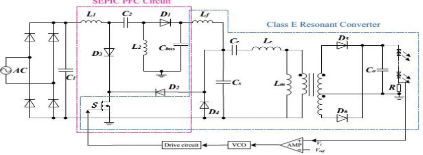
Thus, the proposed single-stage ac/dc converter based on SEPIC circuit and Class-E converter by sharing one active switch is depicted in Fig. 2. It is noticed that there are only two extra diodes added to block a possible voltage difference when the switch S is in OFF state.
The SEPIC circuit consists of inductance L1, L2, capacitance C2, Cbus, diodesD1,D2,D3and a power switch S. It is
designedto work in DCM as a PF preregulator to make the input current sinuous shape and in phase with the input voltage. The Class-E circuit is made up of a choke inductance Lf, a power switch S, a resonant cavity, and load. It steps
down the bus voltage to drive LED, serving as an output regulator. And owing to the soft-switching characteristics, the system efficiency is also improved.
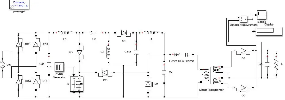
IV.SIMULATIONMODELS
The simulink model is builded with components using the values given in the below table.
Vin 156 Peak Voltage with 60Hz
L1 3 mH
L2 159 μ H
Lf 1.8 mH
Lr 1.4 mH
C1 0.47 μ F
C2 200 nF
Cs 4 nF
Cr 1.8 nF
Cbus 200 μ F
Co 100 μ F
Load 100 W
Working Frequency 100KHz
Open loop Simulation
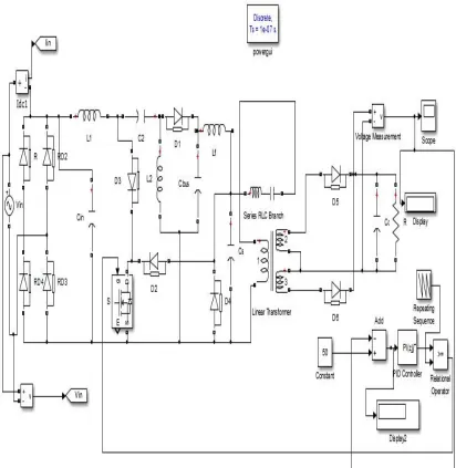
Closed Loop Simulation
Simulink Model of Closed Loop single-stage LED Driver based on SEPIC and Class-E converter by sharing one active switch is shown below
V. SIMULATIONOUTPUT OUTPUT VOLTAGE
Figure 5: Output Voltage Measurement
Output Voltage: 49.28V
LEDs are designed to run on low voltage, direct current electricity. However, most places supply higher voltage (120-277V), alternating current electricity. An LED driver rectifies higher voltage, alternating current to low voltage, direct current. Thus the driver converted the input AC voltage (AC power) to low-voltage DC power required by the LEDs, and protects the LEDs from line-voltage fluctuations.
POWER FACTOR
Power Factor: 0.9998
TOTAL HARMONIC DISTORTION
The total harmonic distortion, or THD, of a signal is a measurement of the harmonic distortion present and is defined as the ratio of the sum of the powers of all harmonic components to the power of the fundamental frequency. THD is used to characterize the linearity of audio systems and the power quality of electric power systems.
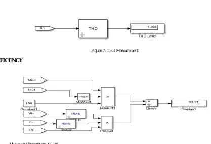
THD: 1.4
Figure 7: THD Measurement
EFFICENCY
MAXIMUM EFFICENCY:93.3%
VI.CONCLUSION
REFERENCES
[1] P. Fang, Y. F. Liu, and P. C. Sen, “A flicker-free single-stage offline LED driver with high power factor,” IEEE J. Emerg. Sel. Topics Power
Electron., vol. 3, no. 3, pp. 654–665. Sep. 2015.
[2] C.-A. Cheng, H.-L. Cheng, F.-L. Yang, and C.-W. Ku, “Single-stage driver for supplying high-power light-emitting-diodes with universal
utility-line input voltages,” IET Power Electron., vol. 5, no. 9, pp. 1614– 1623, Nov. 2012.
[3] S. Moon, G.-B. Koo, and G.-W. Moon, “A new control method of inter-leaved single-stage flyback AC–DC converter for outdoor LED
lighting systems,” IEEE Trans. Power Electron., vol. 28, no. 8, pp. 4051–4062. Aug. 2013.
[4] C.-A. Cheng, H.-L. Cheng, and T.-Y. Chung, “A novel single-stage high-power-factor LED street-lighting driver with coupled inductors,”
IEEETrans. Ind. Appl., vol. 50, no. 5, pp. 2821–2826, Sep./Oct. 2014.
[5] L. Y.-Cun and C. C.-Lin, “A novel primary-side regulation scheme for single-stage high-power-factor AC–DC LED driving circuit,” IEEE