1242 | P a g e
Design & Implementation of Fuzzy Inference System
For Automatic Braking System
D. R. Solanke
1,
K. D. Chinchkhede
2,
A. B. Manwar
3 1,2,3Department of Applied Electronics, SGB Amravati University Amravati, Maharashtra (India)
ABSTRACT
The significant application of fuzzy set theory and fuzzy logic are investigated. Attempt is made to simulate
Fuzzy Logic Controller (FLC) for an Automatic Braking System. Keeping this idea in mind, an initiative is taken
to design and simulate a Fuzzy Inference System (FIS) to perform Antiskid braking in a quasi - virtual
environment. In this paper, the implementation of a Mamdani Fuzzy Inference System has been demonstrated
with the application of an automatic braking system. The system consists of fuzzy logic controller that analyzes
possible accident situation based on the inter-vehicle distance and their relative speed. The controller
determines the sufficient brake pressure required to prevent collision while providing a smooth ride for the
passengers in vehicle. This paper illustrates the simulation and design concepts of fuzzy logic controller for
automatic braking system.
Keywords:
Centroid, Defuzzification, Fuzzification, Fuzzy Inference System, Mamdani
.I. INTRODUCTION
Driver Assistance Systems (DAS) have been attempted as early as in 1950s.The fundamental components of
DAS include Parking Assistance System, Adoptive front lighting system(AFS), Blind spot detection,
Emergency braking system, Collision warning system, Driver drowsiness alert, Adoptive cruise control and
Electronic stability control (ESC). The emergency braking could be achieved through Automatic brake system
(ABS). The ABS is a nonlinear system can not easily be controlled by classical control methods. Several
approaches of system modeling are identified [1]. In present work Fuzzy system modeling (model based
approach) has been used for our research purpose. The uniqueness of a fuzzy modeling approach is its ability to
utilize both qualitative and quantitative information. Qualitative information is human modeling expertise and
knowledge, which are utilized in the form of fuzzy sets, fuzzy logic and fuzzy rules. The theory and design
concepts of Fuzzy Logic Controller presented in [2] facilitate better understanding of the object, which is
essentially that of a control problem in our case. Here we have designed a fuzzy logic controller using fuzzy
logic tool box in MATLAB (Version 7.0.0.499 R2010a 32 bit) software and simulate the designed model using
the Simulink. The main function of the fuzzy logic controller used here is to provide automatic braking without
any manual involvement. Within the several inference strategies, Mamdani‟s technique is the most frequently
used in the existing fuzzy control applications due to its simplicity [3]. Experiments and theoretical
investigations in the referred Literature confirm that Mamdani‟s technique give better performance than that of
other methods in fuzzy control applications [4].The Mamdani Fuzzy Inference System is developed with two
1243 | P a g e
inter-collision distance (m/s) & output is the brake shoe pressure (lbs per unit time). Each input function is
defined with seven membership functions (five triangular & two trapezoidal) and Centroid defuzzification
method is used for extracting the crisp output. The fuzzy controller takes the decision with reference to the
speed and collision distance between the vehicles.The hardware implementation of fuzzy controller for specific
application [5] is presented in simple way in order to realize the proposed model. In order to detect collision
distance of the vehicle, suitable non-contact type sensors and wheel speed sensors can be utilized. Once the
detection is done, these systems either can provide an alert to the driver or take action automatically without any
driver input. Collision avoidance through braking is possible at low vehicle speeds (e.g. below 50 km/h), but it
becomes very difficult at higher vehicle speeds.
This paper has two main contributions. Firstly, a DC motor plant has been designed by solving some physical
equations [6] for second order system and its performance has been observed. Secondly, for the same system a
fuzzy logic controller has been proposed with simple approach and suitable number of rules (Forty nine rules) as
it gives the good performance for larger rule set [7]. The model of the both Fuzzy logic Controller and
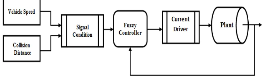
Automatic Braking System (plant model) are represented in figure 1. Simulation results for a second order
system have been demonstrated. The main aim of the work presented in this paper is to create, analyze the
model and carry out the simulation of fuzzy logic controller for non linear dynamic system implemented for
Automatic Braking System.
Figure 1. Auto Braking System Controller
II . ARMATURE CONTROLLED DC MOTOR MODEL
The two input variables (e.g. speed and distance) are taken into consideration to control vehicle speed through
the brake pressure using DC motor linear (actuator) position control. Hence it is necessary to prepare the
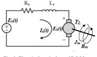
mathematical model of DC motor. The equivalent circuit of a DC motor is depicted in Figure.2, with the
1244 | P a g e
Fig. 2 Electrical equivalent of DC MotorAccording to the Kirchhoff‟s voltage law in armature loop, the electrical equation of motor is described as
(2.1)
where the armature is current, is the back emf voltage and is the armature emf voltage. The
back emf voltage is proportional to the angular velocity (t) of the rotor in the motor [8] [9]; its
electromechanical equation is expressed as
(2.2)
Where is the back emf constant. In addition, the motor generates a torque proportional to the armature
current, given as
(2.3)
Where is the torque constant.
Mechanical dynamics of DC motor is found to be
(2.4)
Take Laplace transform of eq. (1)
(2.5)
1245 | P a g e
(2.6)
(2.7)
Laplace transforms of mechanical system dynamic eqn. (2.4)
(2.8)
If the input voltage is constant, the resulted Armature current , Angular velocity
and torque are also constant in the steady state.
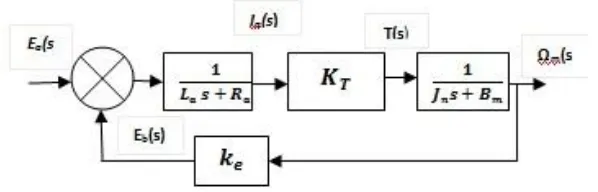
From equations (2.5) (2.7) (2.8) and (2.6), we can draw the block diagram of armature controlled DC motor as
shown below.
Fig. 3. Plant model of DC motor
The feedback formulae to reduce the block diagram
(2.9)
G(s) is the product of the entire block in forward path
1246 | P a g e
Clearly, the motor will encounter two external sources [10], the input voltage to drive the motor and the
torque reacted from the motor speed
.
TABLE I
Parameters used in DC motor
Sr. No. Parameter Value
1 Max. Speed (ωm) 500 rad/sec
2 Max. Armature Current (Ia) 2.0 A
3 Back emf constant (Ke) 0.060 V s/rad
4 Torque constant (KT) 0.06 N-m/A
5 Friction constant (Tf) 0.012 N-m
6 Armature resistance (Ra) 1.2 Ω
7 Armature Inductance (La) 0.020 H
8 Armature inertia (Jm) 6.2×10⁻⁴ N-m-s2/rad
9 Armature viscous friction (Bm) 1×10⁻⁴ N-m-s/rad
According to the parameters mentioned in table I, the transfer function of armature controlled DC motor (plant)
is derived as follows:
III. FUZZY SET THEORY AND FUZZY LOGIC
The concept of Fuzzy Logic (FL) was conceived in 1965 by Prof. Lotfi A. Zadeh of the University of California
at Berkeley [11]. He elaborated his ideas in his paper that introduced the concept of "linguistic variables", which
in this article equates to a variable defined as a fuzzy set [12]. He presented not only a control methodology, but
also a way of processing data by allowing partial set membership rather than crisp set membership or
1247 | P a g e
uncertain, imprecise or without sharp boundaries. The FL poses the ability to mimic the human mind to
effectively employ modes of reasoning that are approximate rather than exact [15]. He also reasoned that
humans do not require precise, numerical information input, and yet they are capable of highly adaptive control.
He suggested that, if feedback controllers could be programmed to accept noisy, imprecise input, they would be
much more effective and perhaps easier to implement. Fuzzy Logic provides a simple way to arrive at an
accurate conclusion based upon vague, ambiguous, imprecise, noisy, or missing input information.
In traditional hard computing, decisions or actions are based on precision, certainty, and vigor. Whereas in soft
computing, tolerance and impression are explored in decision making. With FL, we can specify mapping rules
in terms of words rather than numbers. Computing with the words explores imprecision and tolerance.
According to the authors [16] claimed that Fuzzy logic can easily be implemented on a standard computer.
3.1 Fuzzy Sets and Membership Function
A fuzzy set is an extension of a crisp set. Crisp sets allow only full membership or no membership at all,
whereas fuzzy sets allow partial membership. A fuzzy set A on a universe of discourse Uis characterized by a
membership function that takes values in the interval [0, 1]. Various types of membership functions [17]
were used, including triangular, trapezoidal, generalized bell shaped, Gaussian curves, polynomial curves, and
sigmoid functions. Figure 3.3 shows input (vehicle speed and collision distance) membership functions.
Triangular curves depend on three parameters a, b, and c are given by
(3.1)
In Equation (3.1), a, b, and c are the parameters that are adjusted to fit the desired membership data. The
parameter b is the half width of the curve at the crossover point.
3.2. Logical operations and if-then rules
Fuzzy set operations are analogous to crisp set operations. The most elementary crisp set operations are union,
intersection, and complement, which essentially correspond to OR, AND, and NOT operators, respectively. Let
A and B be two subsets of U. The union of A and B, denoted as , contains all elements in either A or B;
that is , . The intersection of A and B, denoted as A B, contains all the
elements that are simultaneously in A and B; that is ,. The complement of A
is denoted by , and it contains all elements that are not in A; that is , and
1248 | P a g e
In FL, the truth of any statement is a matter of degree. In order to define FL operators, we have to find the
corresponding operators that preserve the results of using AND, OR, and NOT operators. The answer is min,
max, and complement operations. These operators are defined, respectively, as
(3.2)
(3.3)
(3.4)
Most applications use minfor fuzzy intersection,maxfor fuzzy union, and for complementation.
Fuzzy inference systems consist of if–then rules that specify a relationship between the input and output fuzzy
sets. Fuzzy relations present a degree of presence or absence of association or interaction between the elements
of two or more sets. Let U and V be two universes of discourse.
A singleton fuzzy rule assumes the form “if x is A, then y is B,” where , and has a
membership function, where . The „if‟ part of the rule, “x is A,” is called the antecedent or
premise, while the „then‟ part of the rule, “y is B,” is called the consequent or conclusion. In designing a fuzzy
inference system, membership functions are associated with term sets that appear in the antecedent or
consequent of rules.It was Mamdani (1977) who first proposed the minimum implication, and later Larsen
(1980) proposed the product implication.
IV. FUZZY INFERENCE SYSTEM
A fuzzy inference system (FIS) essentially defines a nonlinear mapping of the input data vector into a scalar
output, using fuzzy rules. General model of FIS is shown in Figure 1. It can be seen from the figure that the FIS
contains four components:
A. Fuzzification
B.
Rule baseC.
Inference engineD.
Defuzzification1249 | P a g e
The fuzzifier maps input numbers into corresponding fuzzy memberships. This is required in order to activate
rules that are in terms of linguistic variables. The fuzzifier takes input crisp values and determines the degree to
which they belong to each of the fuzzy sets via membership functions.For a two input fuzzy controller 3,5,7,9
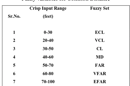
or 11 membership functions for each input are mostly used [18] [19]. The fuzzy set of collision distance was
fuzzified using trapezoid and triangular membership function within the universe of discourse with 7 linguistic
values, as shown in Fig.5, the linguistic values are ECL (Extremely Close, VCL (Very Closed), CL (Closed),
MD (medium), FAR (Far), VFAR (Very Far), and EFAR (Extremely Far).
Table 2.
Fuzzy variables for Vehicle Speed
Sr.No.
Crisp Input Range
(km/hrs)
Fuzzy Set
1 0-40 DSL
2 20-60 VSL
3 40-80 SL
4 60-100 MSL
5 80-120 FST
6 100-140 VFS
7 120-160 EFS
Similarly the linguistic terms for vehicle speed are DSL (Dead Slow), VSL, SL, MSL, FST, VFS and EFS
(Extremely Fast).
Table 3.
Fuzzy variables for Collision Distance
Sr.No.
Crisp Input Range
(feet)
Fuzzy Set
1 0-30 ECL
2 20-40 VCL
3 30-50 CL
4 40-60 MD
5 50-70 FAR
6 60-80 VFAR
7 70-100 EFAR
The required fuzzy membership function for vehicle speed, collision distance and applied brake pressure
1250 | P a g e
Fig. 5. Input membership function for collision distance
Fig. 6. Input membership function for vehicle speed
The inference engine stage consists of fuzzy rules which decide what action to be taken. This is the main block
of the fuzzy controller and constructed from the expert knowledge and experience [20].
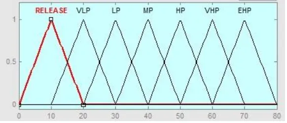
Fig. 7. Output membership function for applied brake pressure
The inference engine defines mapping from input fuzzy sets to output fuzzy sets. It determines the degree to
which the antecedent is satisfied for each rule. If the antecedent of a given rule has more than one clause, fuzzy
operators are applied to obtain one number that represents the result of the antecedent for that rule. It is possible
1251 | P a g e
5.1 DefuzzificationThe input for the defuzzification process is a fuzzy set (the aggregated output fuzzy set), and the output of the
defuzzification process is a crisp value obtained by using some defuzzification method such as the Centroid,
height or maximum. A fuzzy inference system maps an input vector to a crisp output value. The defuzzifier
maps output fuzzy sets into a crisp number [21]. Given a fuzzy set that encompasses a range of output values,
the defuzzifier returns one number, thereby moving from a fuzzy set to a crisp number. The most popular
defuzzification method is the Centroid, which calculates and returns the center of gravity of the aggregated
fuzzy set.
5.2 Centroid defuzzification method
In this method, the defuzzifier determines the center of gravity (Centroid) of B and uses that value as the
output of the FLS. For a continuous aggregated fuzzy set, the Centroid is given by
(4.1)
The Centroid defuzzification method finds the “balance” point of the solution fuzzy region by calculating the
weighted mean of the output fuzzy region. It is the most widely used technique because, when it is used, the
defuzzified values tend to move smoothly around the output fuzzy region.
If the universes are discrete, it is always possible to calculate all thinkable combinations of inputs before putting
the controller into operation. In a table based controller the relation between all input combinations and their
corresponding outputs are arranged in a table. Such array implementation improves execution speed [22]. The
formulated table helps to develop „If–Then‟ rules connecting the 3 variables (ifvehicle speed is x andcollision
distance is y then brake pressure is z). The rules are entered using the Rule editor window. By taking the rule
viewer we can see the effect of each rule on the different values of the variable.
Fig. 8. Mapping between input and output fuzzy variables
V. RESULTS AND DISCUSSION
The rule-based feature of fuzzy models allows for a model considered in a way that is similar to the one that
humans use. Conventional methods for computer automation based on numerical data can be complemented by
1252 | P a g e
aims: analysis, design, control, monitoring, supervision, etc. Rather than as a fully automation technique, fuzzy
modeling should be seen as an interactive method, facilitating the active participation of the user in a
computer-assisted modeling
The experimental results of the controller will be presented in this section. Figure 9 shows the effect of input
and output fuzzy variable observed in rule viewer in fuzzy logic toolbox. The designed FLC model is simulated
with different numbers of membership function and it was found that, Performance accuracy is better with seven
membership functions. So it is more appropriate for proposed system, which has 49 possible control signal (rule
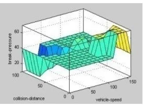
based)[23].The Graphical representation of both the simulation are presented in figure 10 and figure 11 through
Surface mapping, which is a three dimensional plot. It is obtained in the MATLAB fuzzy logic environment,
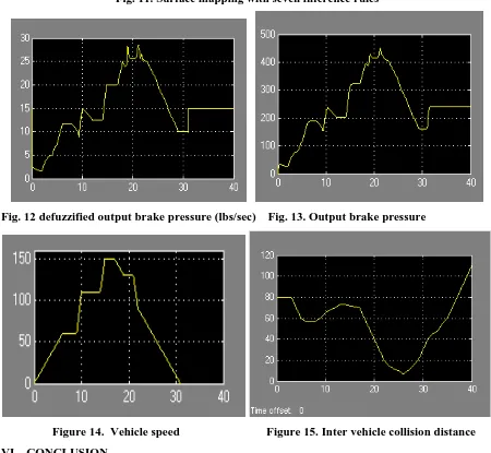
shows the relation between the input and the output values. Figures 14 and 15 shows the user defined control
signals (collision distance and vehicle speed) required for the forty nine rules. These two inputs are then applied
to fuzzy inference engine. The figure 12 shows abrupt changes in applied brake pressure (Defuzzified output)
whereas these fast transitions are slow down by suitable transfer function of plant as shown in figure 13..
Fig. 9. Input and output Fuzzy variables in Rule viewer
1253 | P a g e
Fig. 11. Surface mapping with seven inference rules
Fig. 12 defuzzified output brake pressure (lbs/sec) Fig. 13. Output brake pressure
Figure 14. Vehicle speed
Figure 15. Inter vehicle collision distance
VI. CONCLUSION
The presented experimental results show that it is possible to build an Automatic Braking System with low-price
hardware and inaccurate sensors. The design, implementation and simulation results of Fuzzy Inference System
1254 | P a g e
integrated with Simulink software and Fuzzy Logic Toolbox. Because of the great enhancement in Simulink
block performance, improvement of FIS interfaces, and reinforcement of software functions have become very
efficient and turned into reality. By implementing the proposed control strategy for a multi- purpose
microprocessor, custom hardware can be developed with ABS application Authors believe that using advanced
electronics hardware if combined with software, ABS model along with the test vehicle will be capable to tackle
the accidental situation.. We expect that auto braking features provide the biggest benefits to collision-avoidance
system that would brake of its own, if the driver is not able to avoid a forward collision.
REFERENCES
[1] Disha Sharma, “Designing and Modeling Fuzzy Control Systems”,International Journal of Computer
Applications Vol.16issue 01, February 2011,pp.46-53
[2]. YING, PENG. “Intelligent control for 2DOF helicopter via genetic algorithms”. scholarbank.nus.edu.sg,
Diss. 2003
[3]. Shuwei Guo, Liliane Peters and Hartmut Surmann, “Design and Application of an Analog Fuzzy Logic
controller”, IEEE transaction on fuzzy systems, vol. 4 issue 4, Nov 1996, pp. 429 – 438
[4]. C. C. Lee, Fuzzy Logic in Control Systems: Fuzzy Logic Controller”, IEEE Transaction on Systems,
Man, and Cybernetics, vol. 20, issue 02, 1990, pp. 404-435.
[5]. M D Hanamane, R R Mudholkar and S R Sawant, “Implementation of fuzzy temperature controller using
microprocessor”, Journal of Scientific and Industrial Research, Vol. 65, Feb 2006, pp.142-147
[6]. Yasser Ali Almatheel and Ahmed Abdelrahman” Speed control of dc motor using fuzzy logic controller”,
2017 IEEE International Conference on Communication, Control, Computing and Electronics, Khartoum,
Sudan.
[7]. Y.Yongquan, H.Ying and Z.Bi, “The dynamic fuzzy method to tune the weight factors of Neural fuzzy PID controller,” 2004 IEEE international Joint conference on Neural networks, pp. 2397-2402.
[8]. Ananthababu B. , “Fuzzybased speed control of BLDC motor with bidirectional DC-DCconverter”,
International Conference on Green Engineering and Technologies, 2016 , pp. 01 – 06.
[9]. Himanshu Choudhary, Shahida Khatoon and Ravindra Singh, “ANFIS Based Speed Control of DC
Motor”, 2nd International Conference on Innovative Application of computational Intelligence on Power,
Energy and Control with their Impact on Humanity (CIPECH-16), 2016, pp 63-67.
[10]. Yong Ping-Chen, “Dynamic System Simulation and Implementation.” NCTU Department of Electrical
and Computer Engineering, Spring Course, 2015, pp 2.1-2.3
[11]. Zadeh, Lotfi A.. "Fuzzy sets". Information and Control. Vol..8 issue 3, 1965, PP.338–353.
[12]. Zadeh, Lotfi A.. "Outline of a new approach to the analysis of complex systems and decision processes".
IEEE Transactions on Systems, Man and Cybernetics. 1973 vol.1: 28–44.
[13]. P. Singhala, D. N. Shah and B. Patel, “Temperature Control using Fuzzy Logic”, International Journal of
1255 | P a g e
[14]. Harpreet Singh, Madan M. Gupta, Thomas Meitzler, Zeng-Guang Hou, Kum Kum Garg, Ashu M. G. Solo, and Lotfi A. Zadeh7, “Real-Life Applications of Fuzzy Logic”, Hindawi Publishing Corporation
Advances in Fuzzy Systems Volume 2013, pp.01-03
[15]. Absal Nabi,”Design of Fuzzy Logic PD Controller for a Position Control System”, International Journal
of Engineering and Management Research, Volume-3, Issue-2, April 2013, pp. 31-34
[16]. Tarun Kumar Das, Yudhajit Das, “Design of A Room Temperature And Humidity Controller Using
Fuzzy Logic”, American Journal of Engineering Research, Volume-02, Issue-11, pp-86-97
[17]. Grzegorz Filo, “Modeling of fuzzy logic control system using the MATLAB Simulink program”,
CzasopismoTechniczne. Mechanika, Vol.107, issue 8,2010, pp.73-81.
[18]. S.Chopra, R.Mitra and V.Kumar, “Fuzzy controller: Choosing an appropriate & smallest rule set ”,
International Journal of Computational Cognition, Vol.3, issue.4, 2005, pp. 73-78.
[19]. S.R.Vaishnav, Z.J.Khan, “Design and Performance of PID and Fuzzy Logic Controller with Smaller Rule
Set for Higher Order System” , Proceedings of the World Congress on Engineering and Computer
Science ( WCECS 20070), October 24-26, 2007, San Francisco, USA, pp.855-858
[20]. P. A. Saudagar, D. S. Dhote, K. D. Chinchkhede, “Design of Fuzzy Logic Controller for Humidity
Control in Greenhouse”, International Journal of Engineering Inventions Volume 1, Issue 11
,December2012,pp. 45-49
[21]. Mrs. A.A Thorat, Suhas Yadav, S.S.Patil, “ Implementation of Fuzzy Logic System for DC Motor Speed Control using Microcontroller”, International Journal of Engineering Research and Applications
,Vol. 3, Issue 2, March -April 2013, pp.950-956
[22]. Jantzen, Jan. "Design of fuzzy controllers." Technical University of Denmark, Department of
Automation, 1998, pp.362-367.
[23]. AA Bature, Mustapha Muhammad, Auwalu M. Abdullahi, “ Design And Real Time Implementation Of
Fuzzy Controller For DC Motor Position Control”, International journal of scientific & technology