Design and Implementation of PLC Based
Control Panel for Hydraulic Assembly Press
V.Mahesh Kumar 1, A.Sivasankar2, G.Prabakaran3, R.Dhanabal4, A.Muthu Krishnan5
Assistant Professor, Jay Shriram Group of Institutions, Tirupur, Tamilnadu, India1
UG Scholar, Jay Shriram Group of Institutions, Tirupur, Tamilnadu, India2, 3,4&5
ABSTRACT: Automation is basically the delegation of human control functions to technical equipment, aimed to achieve higher productivity, superior quality and efficient use of energy and raw materials. Now a days PLC serves this purpose. PLC is an industrial computer that monitors input, makes decision based on its program and controls output to automate a process or machine. It is used to reduce human efforts, to get maximum efficiency from machine and control them with human logic. It can be effectively used in applications ranging from simple control such as small number of relays to complex automation systems. The PLC used in this project is micro PLC of the SIEMENS Company’s S71200 SIEMANTIC. The operations of PLC can be done through control panel. A control panel is an area where control or monitoring instruments are displayed. Conventional control panels are most often equipped with push buttons and analog instruments. This control panel is designed to control the 5T hydraulic flywheel assembly press. The flywheel which is used in four stroke engines.The control panel consists of PLC kit, bus bars, transformers, SMPS, protection and safety circuits, I/O terminals, alarms, lamp, timers, indicators, relays and contactors. The output terminals are suitably connected to the valves, pumps, motor etc., of the machine. The panel wiring reduces the complexity in the system hardware. This system is widely used in automobile industries for assemble freewheel which involves the gear wheel assembly. As PLC is a real time system, it is most suitable for flexible and accurate operation of the machine.
KEYWORDS: flywheel, hydraulic assembly, automation.
I.INTRODUCTION
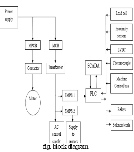
II.BLOCK DIAGRAM
fig. block diagram
MCB:
MCBs or Miniature Circuit Breakers are electromechanical devices which protect an electrical circuit from an over current. The over current, in an electrical circuit, may result from short circuit, overload or faulty design. An MCB is a better alternative to a Fuse since it does not require replacement once an overload is detected. Unlike fuse, an MCB can be easily reset and thus offers improved operational safety and greater convenience without incurring large operating cost. The principal of operation is simple. An MCB functions by interrupting the continuity of electrical flow through the circuit once a fault is detected.
CONTACTOR:
A contactor is an electrically controlled switch used for switching an electrical power circuit, similar to a relay except with higher current ratings and a few other differences.Contactors typically have multiple contacts, and those contacts are usually normally-open, so that power to the load is shut off when the coil is de-energized. Perhaps the most common industrial use for contactors is the control of electric motors.
CONTROL TRANSFORMER:
A control transformer, (also known as an industrial control transformer, or a control power transformer, or even a machine tool transformer), is essentially an isolation transformer that provides excellent voltage regulation. A control transformer is very often designed to produce a high level of secondary voltage stability during brief periods of overload condition, typically known as inrush current.
SMPS:
RELAY:
A relay is usually an electromechanical device that is actuated by an electrical current. The current flowing in one circuit causes the opening or closing of another circuit.When there is current through the coil of wire on the control side a magnetic field is produced. This magnetic field attracts the armature and closes the contacts on the load side. In
normally open (NO) relay the contacts are in normally open state. When the coil is energized the contacts are closed.
In normally closed (NC) relay the contacts are in normally closed state. When the coil is energized the contacts are
opened.
INDUCTION MOTORS:
A motor is nothing but an electro-mechanical device that converts electrical energy to mechanical energy Induction motors are widely used in industrial drives because they are rugged, reliable and economical. An induction motor is an AC electric motor in which the electric current in the rotor needed to produce torque is obtained electromagnetic induction from the magnetic field of the stator winding.
PROXIMITY SENSOR:
A proximity sensor is a sensor able to detect the presence of nearby objects without any physical contact.Aproximity sensor often emits an electromagnetic field or a beam of electromagnetic radiation (infrared, for instance), and looks for changes in the field or return signal. The object being sensed is often referred to as the proximity sensors target.
LVDT:
The term LVDT stands for the linear variable differential transformer. It is the most widely used inductive transducer that convert the linear motion into the electrical signals. LVDT works under the principle of mutual induction, and the displacement which is a non-electrical energy is converted into an electrical energy. The output voltage of an LVDT is linear function of core displacement.
LOAD CELL:
Load cell is a type of transducer which performs the functionality of converting force into an electric output which can be measured. Piezoelectric load cells work on the same principle of deformation as the strain gauge load cells, but a voltage output is generated by the basic piezoelectric material - proportional to the deformation of load cell. The acting pressure was displayed in special meter.
PLC:
Programmable Logic Controller (PLC) is a digital computer used for the automation of various electro-mechanical processes in industries, such as control of machinery on factory assembly lines. These controllers are specially designed to survive in harsh situations and shielded from heat, cold, dust, and moisture etc. PLC consists of a microprocessor which is programmed using the computer language.
The program is written on a computer and is downloaded to the PLC via cable. These loaded programs are stored in non – volatile memory of the PLC. During the transition of relay control panels to PLC, the hard wired relay logic was exchanged for the program fed by the user. A visual programming language known as the Ladder Logic was created to program the PLC.The analog and digital input modules are connected to plc for connecting LVDT and load cell.
SCADA:
SCADA systems deploy multiple software and hardware elements that allow industrial organizations to Monitor, gather, and process data, Interact with and control machines and devices such as valves, pumps, motors, and more, which are connected through HMI (human-machine interface) software. SCADA also records and logs all events into a file stored on a hard disk or sends them to a printer. SCADA applications warn when conditions become hazardous by sounding alarms.
SCADA software was implemented in this project. SCADA software for this machine has able keep the records of 5 years such as number of cycles, Motor on time, machine working status, etc.
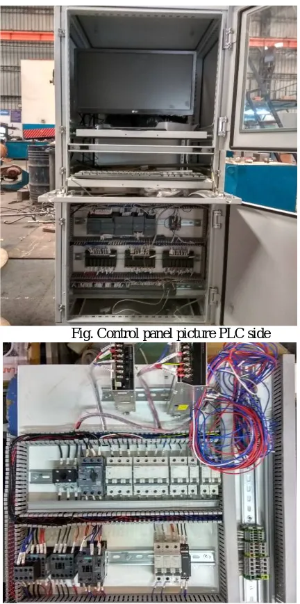
III.CONTROL PANEL
A panel board is an element of a system used to supply electricity .primary function is to divide an electrical feed into supplementary circuits while providing shielding and protection for each circuit in an enclosed space.
Panel board is tend to made up of circuit breaker, bus bars, switches, relays and other protective equipments. The panel board consists MS channel to place the components and PVC channels to provide wiring
The machine control box was separately placed which consists push buttons, selector switches& load cell meter.
Fig. Control panel picture PLC side
IV.SOFTWARE DETAILS
The software used in the proposed system of our project is TIA13. It is an overall project management tool that allows for complete system (multiple controllers, HMIs, networks, SCADAs,etc.) to be programmed, monitored, saved and stored all in one software package . The ladder logics are developed using TIA13. The details of the software is described in this chapter. The ladder logics are developed in multiple modules.
Fig. TIA portal
Design steps of TIA13
Step1: Start
Step2: Create a new project Step3: Add devices
Step4: Device configuration
Step5: Communication through Ethernet Step6: Program downloading
Step7: Program execution in machine Step8: Stop
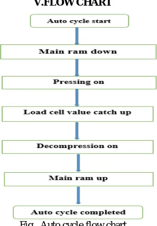
V.FLOW CHART
AUTO CYCLE START
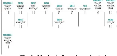
The auto or manual mode was decided by using the selector switch. When auto mode was selected the PLC enables the auto cycle. The freewheel gear wheel was placed in the die and the auto cycle was started
Fig. ladder logic for auto cycle start
MAIN RAM DOWN
When the machine is ready for the cycle, the PLC enable the output to the loading valve. So that the main ram starts to move down. The program was adjusted change the speed of the main ram.
Fig. ladder logic for main ram down
PRESSING ON
On reaching the proximity sensor mounted on the machine, the signal is sent to the PLC. Now the ram starts pressing the material at the specified pressure after receiving signal from proximity sensor mounted. The pressure can be up to 160 bars. The
Fig. ladder logic for pressing on
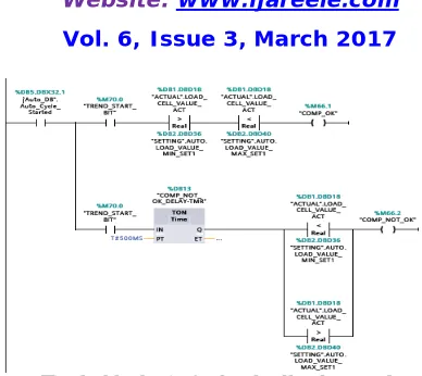
LOAD CELL VALUE CATCHUP
Fig. ladder logic for load cell value catchup
DECOMPRESSION
After preset pressure was attained by load cell the oil pressure was decomposed.
Fig. ladder logic for decompression
MAIN RAM UP
After the decompression process, the main ram is moved up to its original position. It is confirmed by proximity sensor mounted on the top.
Fig. ladder logic for main ram up
AUTO CYCLE COMPLETE
After all the process the cycle was completed, and the machine is ready for next cycle.
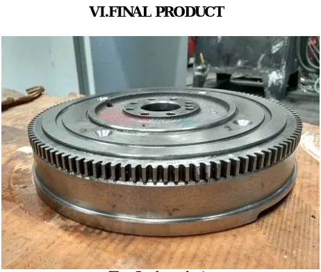
VI.FINAL PRODUCT
Fig. final product
VII.CONCLUSION
Thus in all industries many manual operations are done and many accidents also according for the operators and thus it cannot be avoided at any situations. We can make the manual operations by automatic and thus it reduces the manual operations as well as the accidents occurring to the operators can be avoided. The PLC operation involves the operation with SCADA which is very easy to operate from a personal computer itself. Thus the operating time also get reduced with high production. Today industrial automation software requirements include capability to implement application involving widely distributed devices, high reuse of software components, formal verification that specifications are fulfilled.
REFERENCES
[1]Erickson,K.T.(1996) ‘programmable logic controller’.potential IEEE,Vol.5,pp.14-17
[2]RathodBalasahepS,Sathish.M.Rajmane ‘A case Study on design of a flywheel for punching press operation’ IJEAT, Vol.3,april-2013 [3]Flochova,J, Auxt,F ,May2007, “decision and control”,IEEE transactions on automation design,vol.46,no.pp.1874-1879
[4]Frank D.Petruzella ,” programmable logic controller”, Tata Mcgraw Hill,3rd edition,2005 [5]‘Omran selection guide’, vol.3-2013
[6]‘Power engineering guide-Siemens’ edition 8.0 [7]www.electrical4u.com