1056 |
P a g e
Reduction in sidelobe and SNR improves by using Digital
Pulse Compression Technique
Devesh Tiwari
1, Dr. Sarita Singh Bhadauria
2Department of Electronics Engineering,
Madhav Institute of Technology and Science, Gwalior, (India)
ABSTRACT
Digital pulse compression is the technique to convert short pulse to long pulse because energy content
of long pulse with low peak power would be the same with short pulse having high peak power. In this
paper pulse compression is performed by Matched Filter in signal processing environment. At some
finite interval of time the high peak amplitude of signal with narrow bandwidth gives the energy of the
transmitted pulse from the radar. Matched filter gives the signal to noise ratio at the receiver output.
Sidelobe reduces to -63 db. Signal to noise ratio (SNR) improves to 12dB. Non linear frequency
modulated (NLFM) pulse compression is used. They have been claimed to provide a high range
resolution, improved SNR, low cost, good interference mitigation and spectrum weighting function.
High range side lobe can cause poor performance in both target and weather detection. The results
have been validated using experimental data.
Keywords
:
Digital pulse compression, FFT, IFFT, peak side lobe level, Linear frequency
modulation (LFM), Non linear frequency modulation(NLFM), matched filter, side lobe
suppression filter.
I. INTRODUCTION
The Pulse compression is the technique in which a long duration pulse with high energy is modulated.Linear
frequency modulated or phase modulated increases the bandwidth of the transmitted signal. Now these
modulated pulse is transmitted through parabolic reflector in radar. These long duration pulse strikes with the
different number of targets, echo returned to the receiving antenna. These signal passed through matched filter
and noise present in the signal is compressed by the matched filter processor. Pure matched filter gives a low
side lobes. The NLFM signals also assure better detection rate characteristics and they are more accurate in
range determination.
1057 |
P a g e
In the pulse compression NLFM pulse resolving closely placed multiple targets known as range resolution.
Another advantage it reduces sidelobe to many possible preferable values. The mathematical expressions is
discussed to achieve the desired value. The NLFM signal is given tothe matched filter. The output of the
matched filter is given to the sidelobe suppression filter.
S(n) is the transmitted signal. y(n) is the output signal. A compressed output received in which sidelobe reduces
by supressionsidelobe filter. The description is given below
y(n
)
o/pSidelobe suppression to -63 dB.
II. PULSE COMPRESSION METHOD
This section includes some of the discussions of journal papers on RADAR pulse compression method.
Shinriki, et al.,[8] have given a new idea of pulse compression method for normal pulse. In this proposed
method a filter whose impulse response in frequency domain is the ratio between the desired waveform and
input signal in frequency domain. This method has the advantage of compressing to arbitrary pulse width given
by the desired waveform and this method yields low peak sidelobe level.
Justin Sagayaraj M, Manisha Sanal, have given few sample optimum biphase codes with low sidelobes. They
have Optimized FIR filters for digital pulse compression waveform. They have achieved low sidelobe level of
-35 dB to -40 dB.
M. Archana, M. Gnanapriya have given the idea of low power pulse compression RADAR with
Sidelobesuppresion. This method discuss the LFM pulse compression method in frequency domain. The higher
sidelobe level is suppressed by using different windows method.
III. EVALUATION OF PARAMETERS
The parameters are peak sidelobe ratio (PSR) is given by
P
ulse compression ratio is given byWhere c is the speed of light, τ is the pulse width.
The instantaneous frequency modulation function of tangent based NLFM is given by
PCR
=
PSR = 10
(1) Matched
filter
1058 |
P a g e
ƒ (t)
=
, -
< t <
(2)where γ = , α > 0 is sidelobe control factor. β is the bandwidth
.
Hybrid Non Linear Frequency Modulation can be implemented. The instantaneous frequency of NLFM is
given by
ƒ (t) = [ + , - < t < (3)
The parameter represents Linear Frequency Modulation term. While the parameter is chebyshev shaped
spectrum i.e. constant sidelobe level.
The Phase of NLFM is obtained by integrating the instantaneous frequency.LFM signal has the higher peak
sidelobe level. Non linear frequency modulated signal has reduced the sidelobe level to greater extent.
III. DESIGN OF MATCHED FILTER
Matched filter improves the SNR at the output of the receiver. Matched filter is a system used in the initial stage
of digital system receiver. Matched filter is used to decrease Probability error by increasing Signal to Noise ratio
(SNR)
.
The matched filter has an adaptability to the signals of same waveform despite different amplitude and time
delay. Signal s(t) matches to the signal αs(t-τ). The general method is to use MATLAB tools. To generating
ideal chirp signal, filter use this chirp signal gives the spectrum and compress the result because echo signal is
not ideal, the noise and clutter are not identical. So SNR at the output of the receiver.
( ) = (4)
Where, S(t) =
No(t) = df
No(t) is the output noise at receiver. S(t) is the signal received at the output. is the fourier transform of the
input signal. H(f) is the matched filter response.
Now by using Schwartz inequality
| |2= | |
H(f) = Si(f) (5)
This is our required matched filter expression.
= (6)
Where Eo is the output energy and No is the output noise. Signal to noise ratio is inversely proportional to noise
1059 |
P a g e
transmitted signal. Basically the amplitude is increased at some time interval and pulse width of noise is
compressed. SNR improves at the receiver of the pulsed radar.
IV. COMPARISION OF WINDOW TECHNIQUES
HAMMING WINDOW
:
It is used to find out leakage factor, relative sidelobe attenuation, main lobe width(-3dB).
(7)
When N = 140
Leakage factor = 0.04%
Relative sidelobe attenuation = -42.68 dB
Main lobe width (-3dB) = 0.018555
Fig2.
Sidelobe attenuation curves, N = 140When N = 124
Leakage factor = 0.03.%
Relative sidelobe attenuation = -42.6 dB
Main lobe width (-3dB) = 0.019531
1060 |
P a g e
KAISER WINDOW
(8)
When β = 0.5 and α = 140
Leakage factor = 8.6 %
Relative sidelobe attenuation = -13.6 dB
Main lobe width (-3dB) = 0.012695
Fig4. Sidelobe attenuation curves,
When β = 0.5 and α = 124
Leakage factor = 8.39 %
Relative sidelobe attenuation = -13.6 dB
Main lobe width (-3dB) = 0.013672
Fig5. Sidelobe attenuation curves,
it is - Hence for above comparision hamming window technique provides better result. Leakage factor is always
less in hamming window compared to Kaiser window for finding out the sidelobe attenuation. In hamming
window technique sidelobe attenuation provides better result as -42.69 dB. In Kaiser window technique 13.6 dB.
V. RESULT OF MATLAB SIMULATION
The compressed output pulse is obtained in matlab. The long duration pulse is compressed and at some time
1061 |
P a g e
.
Fig6. Theinitilpulse compression.
Sidelobe values lies between -20dB to 20dB.
The reduction in the sidelobe is the major work in this paper. For this reduction signal waveform analyser tool
is used to get desired result. The ratio of Peak sidelobe power to the main lobe power is find out.
Fig7.The shape of ambiguity surface function.
The reduction in the sidelobe for mismatching filter is a hecting process for some window techniques. For this
mismatching filter the Kaiser window gives the appropriate reduction in the sidelobe.
Fig8. The sidelobe representation waveform.
The sidelobe peak value is approx. 62dB.
1062 |
P a g e
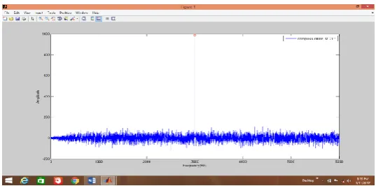
The amplitude of sidelobe lies -62dB to – 70dB.
Fig10. The sidelobe reduces pulse.
It reduces to – 42 dB in MATLAB environment.
Fig11. ROC curves evaluate SNR = 12dB.
12 dB represented by above red curves which is having some initial probability of pulse detection ( ).
Probability of false alarm is very low value( ).
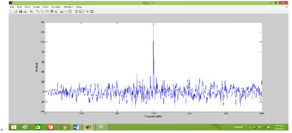
Fig 12. The digital pulse compression output.
Pulse compression ratio = 37.71
VI. CONCLUSION
The real time generation of LFM and NLFM waveform is used precisely that gives a proper range sidelobe
levels. The NLFM processing algorithm has the advantage to improve the shape of the compression pulse
waveform. The effective sidelobe reduction technique NLFM algorithm is used. It has a wide applicability in the
pulse compression technique. The higher sidelobe level reduces by using different window techniques. The
parameters peak sidelobe level, main lobe width, compressed pulse width of hamming and Kaiser window is
calculated. The window are used according to their requirement to suppress the sidelobes. This paper examines
1063 |
P a g e
signal has been simulated and implemented using MATLAB. Digital pulse compression by matched filter
perform in matlab software with the help of programming. Pulse compression is implemented to improve the
radar range resolution long pulse for long range detection. Both matlab simulation and implementation results
show a very good agreement with the theory and concepts of pulse compression. Pulse compression with the
reduced sidelobes is the main work area.
In Future work Costas Pulses can be used that follow the frequency hopping sequence gives sidelobe levels
which is 1/N of the mainlobe peak for any delay and Doppler shift. Work can also be extended to add some
Doppler effect and constant false alarm rate algorithm for finding speed, eliminating clutter and echoes
disturbances.
REFERENCES
[1] M. I. Skolnik, “Radar Handbook” 3rd edition, Mc-Graw Hill 2008.
[2] B. R. Mahafza“Radar signal analysis and processing using MATLAB”, CRC Press 2009.
[3] Mark A Richards, “Fundamentals of Radar signal Processing, Tata Mc Graw Hill, 2005.
[4] Xiaojun Wang, Shuhua Wei, GuochenAn, “system Design and Experimental Analysis of digital pulse
compression based on FPGA”, 2008.
[5] Vikram Thakur Amit kumarvermaParamanandajena, G.Surya Prasad, Design and Implementation of FPGA
based digital pulse compression via fast convolution using FFT-OS” IIT Bhubaneswar, india 2015.
[6] Adnan Orduyilmaz, Gokhankara, Ali caferGurbuz, Murat Efe, Real time Pulse compression radar waveform
generation and Digital Matched Filtering, 2015.
[7] N. Levanon and E.Mozeson, “Radar Signals” Wiley and Sons, 2004.
[8] A. V. Oppenheim, R.W. Schaefer, and J.R. Buck, “Discrete time signal processing”, Prentice-Hall,
Englewood Cliffs, NJ,1998.
[9] A.W. Doerry, “Generating Nonlinear FM Chirp waveform for radar ,” Technical report, Sandia Technical
Laboratories, September, 2006.
[10] S. Wang, M. Grabb, J. Poplawski, “ Nonlinear- FM Waveform Design Procedure,”communications and
signal processing laboratory, technical report, Sandia Technical Laboratories, September, 2006.
[11] S. K. Mitra, “Digital Signal Processing, A Computer based approach ,” 3rd edition, 2006.
[12] Bijay Kumar Sa, Optimisingsidelobes and Grating lobes in frequency modulated pulse compression, NIT
Rourkela, 2013.
[13] M. Archana, M. Gnanapriya, power LFM Pulse compression RADAR with sidelobe suppression,
international journal of advanced research in electrical, electronics and instrumentation engineering, 2014.
[14] RaghupatruniJeevanmai, Dr. N.Deepika Rani, sidelobe reduction using frequency modulation pulse