*
Pilot study about the micro hydropower generation by use of
flow induced vibration phenomenon
Yoshifumi Yokoi1,*
1National Defence Academy of Japan, Department of Mechanical Engineering, 1-10-20 Hashirimizu, Yokosuka 239-8686, Japan
Abstract. In order to construct a micro power generation system using a piezo-electric element, power generation was tried using excitation oscillation of the bluff cylinder by the vortex shedding from the bluff cylinder. The bluff cylinder consists of a board spring section in which the piezo-electric element was attached, and a body section. The bluff cylinder was inserted into the water flow, the shape and the submersion depth of the bluff cylinder, and the flow velocity were varied, and the power generation characteristic was investigated. As a result, it was found that it can generate electricity by vortex excitation. It was found that the length and the submersion depth of the body section influence power generation. It was shown that the power generation characteristic changes with cross-sectional shape of the bluff cylinder. The most suitable state was the case where the submersion depth was set to 140 mm with a circular cylinder with a span length of 250 mm. It is important to choose the power generation object which suited the use purpose.
1 Introduction
Considering an energy problem in recent years, it is interesting to exploit effectively the hydraulic power energy of the small scale and medium scale which is not yet used. As the example, the development and utilization in a river, an irrigation canal, etc. of low drop micro hydropower generation are performed actively. Those trends were reported by Turbomachinery Society of Japan [1, 2]. In realization of the plan, there are many matters which cannot be suitable by extension of the technique developed in the large-scale water-power generation of the concentration of all aspect of a society in one place. Therefore, development of new power generation technique or some method is needed. In response to such background, the power generation method using the self oscillation (vortex excitation) by the vortex shedding from the bluff cylinder placed into the flow is proposed by Bemitsas et al. [3], Uno & Kawashima [4], Koide et al. [5] and Hiejima et al. [6]. In order not to have a rotation mechanism the merit of vortex excitation type power generation is a maintenance-free. And the assembly and installation are also easy. Furthermore, since there is no impeller, power generation is possible, without damaging the living thing which lives in water by rotation of the impeller.
In this study, the piezo-electric element was used for the power generation element, and power generation was tried using excitation oscillation of the bluff cylinder by the vortex shedding from the bluff cylinder. Design manufacture of the power generation bluff cylinder was performed. And some tests were performed by the power generation bluff cylinder which was inserted into the
water flow. In such tests, the shape and the submersion depth of the submersion section, and the flow velocity were varied, and the power generation characteristic was investigated.
2 Experimental apparatus and method
2.1 Outline of experimental apparatus
Experimental apparatus consists of a closed circuit water channel, a test bluff cylinder-traverse apparatus, and an oscillating frequency measuring device. The closed circuit water channel is the apparatus (water capacity 4 m3) used by the previous report [7]. The sizes of the test
section were 2 m in length, 800 mm in width, and 430 mm in depth, the flow velocity range was 0 - 1.2 m/s, and the turbulence to the average flow velocity was less than ±1.5 %. The test bluff cylinder-traverse apparatus is 2 axis dial slight movement type, and those moving ranges are 72 mm and 64 mm, respectively. Those directions of moving are the depth direction and the width direction. As for the oscillation frequency measuring device, the storage oscilloscope (KENWOOD, DCS-7020) was used.
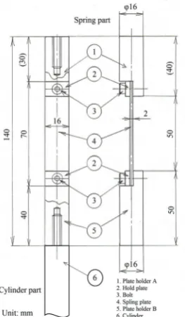
2.2 Test cylinders and generators
Fig. 1. The schematic drawing of a test cylinder spring section
Fig. 2. Body section shape of the test cylinder (circular cylinder, square cylinder, and triangular cylinder)
(a) (b)
Fig. 3. The aspect of the power generation object, (a) piezo-electric sensor, (b) piezo-electric buzzer
Fig. 4. The photograph of the situation where the test cylinder was set in the traverse apparatus
mm made from vinyl chloride. As for the body, the circular cylinder, the triangular cylinder, and the square cylinder were prepared. Figure 2 shows the shape of those cylinders. The length of circular cylinder is two kinds, 250 mm and 500 mm, and the diameter is 16 mm. The length of a triangular cylinder and a square cylinder is 250 mm, and those side lengths are 15 mm.
The power generation object was set in the section of the board spring. The used power generation objects were shown in Fig. 3. One of which is a piezo-electric sensor (Tokyo sensor company, DT1-028 K/L) and the other is a piezo-electric buzzer (SPL company, PT08-Z185). These two kinds of power generation objects are made by different material and the manufacture method.
2.3 Experimental parameters
Experiment parameters are the length of bluff cylinder, the submersion depth of the body (draft), its setting
posture, and water flow velocity. The submersion depth of the body is three kinds (70, 140 and 210 mm). The posture of a triangular cylinder and a square cylinder is in the state where the angle was directed to the flow, and the state which directed the plane. The water flow velocity was varied to 44 steps in the range of 0 - 1.2 m/s.
2.4 Experimental procedure
The experiment procedure is the following. The power generation object is set in the board spring section of the test bluff cylinder, and the test bluff cylinder is attached in the traverse apparatus. The direction is decided to oscillate right-angled to the flow in the case of the attachment. The body is sunk in the target submersion depth. An aspect that it was set based on the procedure is shown in Fig. 4. The target flow velocity is caused by inverter operation of the pump of the closed circuit water channel. The voltage variation waveform from the power generation object sensor is observed with the storage oscilloscope, and output voltage and frequency are measured. Here, the frequency measured the signal of voltage waveform, observed the time jitter with the storage oscilloscope, and determined for fluctuation frequency.
Traverse apparatus
To storage oscilloscope Power generation
object
70
2.5
2.0
1.9
2
2.2
250
140
2.2
1.7
1.7
1.9
2
210
2.1
1.6
1.6
1.9
205
0.9
380
0.8
500
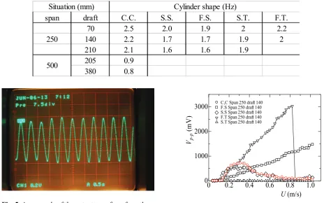
Fig. 5. An example of the output waveform from the power generation object
0 0.2 0.4 0.6 0.8 1.0 0
1000 2000 3000
U (m/s) Vp-p
(m
V
)
C,C Span 250 draft 140 F.S Span 250 draft 140 S.S Span 250 draft 140 F.T Span 250 draft 140 S.T Span 250 draft 140
Fig. 6. Relationship between flow velocity and output voltage, in the case of circular cylinder
3
Experimental result and discussion
3.1 Measurement of natural frequency
The result of having measured the characteristic vibration of the overall system of the test bluff cylinder with a board spring is shown in Tab. 1. The meaning of the symbols used in the table are the following. The symbol "C.C." is a circular cylinder, the symbol "S.S." is the square cylinder which directed the angle to the flow, the symbol "F.S." is the square cylinder which directed the plane to the flow, the symbol "S.T." is the triangular cylinder which directed the angle to the flow, and the symbol "F.T." is the triangular cylinder which directed the plane to the flow. When the submersion depth of the body (draft) became shallow, it was confirmed that the character frequency as the overall system tends to become high.
3.2 Power generation characteristic test
Since the piezo-electric element reacts to unsteady stress, it can generate electricity by the lift alternately produced by the Karman vortex. An example of the power generation voltage waveform is shown in Fig. 5. In the beam which generally has a uniform section, if amplitude becomes large near critical oscillation
Side view Bird 's-eye view (a)
Side view Bird 's-eye view (b)
Side view Bird 's-eye view (c)
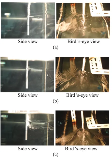
Fig. 7. Flow feature around circular cylinder, (a) flow
velocity; 0.13 m/s, (b) flow velocity; 0.38 m/s, (c) flow velocity; 0.79 m/s
Side view Bird 's-eye view (a)
Side view Bird 's-eye view (b)
Side view Bird 's-eye view (c)
Side view Bird 's-eye view (d)
Fig. 8. Flow feature around square cylinder, (a) sharp
square cylinder (S. S.), flow velocity; 0.29 m/s, (b) sharp square cylinder (S. S.), flow velocity; 0.6 m/s, (c) Flat square cylinder (F. S.), flow velocity; 0.6 m/s, (d) Flat square cylinder (F. S.), flow velocity; 1.02 m/s the range of the flow velocity 0.22 - 0.38 m/s,
considering this matter, as for the circular cylinder body and the sharp square body, it turns out that it is in the setting situation of having been most suitable for the use.
3.3 The aspect of the flow around the bluff cylinder
Figures 7 - 9 show the aspect of the flow of the circular cylinder, the square cylinder, and the triangular cylinder. The length of those bluff cylinders used here was 250mm. Figure 7 shows the aspect of the flow when sinking the circular cylinder 140 mm and varying the flow velocity. Where a right-hand side photograph is seen from the width side (underwater), a left-hand side photograph is in the state which looked at behind from slant. In Fig. 7(a), it is shown that the dimple of the water surface has produced alternately behind the circular cylinder. That shows that the Karman vortex is formed. The difference of a water level has not occurred between the upstream side of the circular cylinder, and the down stream side. In Fig. 7(b), the length which forms the dimple of the water surface of the circular cylinder behind becomes short, and an aspect that the wave is pulled from the circular cylinder can be seen. The difference of the water level can be seen have occurred between the upstream side of the circular cylinder, and the down stream side. As for this state, the value of the produced voltage becomes the maximum so
Side view Bird 's-eye view (a)
Side view Bird 's-eye view (b)
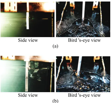
Fig. 9. Flow feature around triangular cylinder, (a)
sharp triangular cylinder (S. T.), draft; 70 mm, flow velocity; 0.6 m/s, (b) Flat triangular cylinder (F. T.), draft; 140 mm, flow velocity; 0.6 m/s
0 0.2 0.4 0.6 0.8 1.0 0
1000 2000
U (m/s)
Vp-p
(m
Fig. 10. Relationship between flow velocity and
output voltage, in the case of circular cylinder, the piezo-electric buzzer was used
0 0.2 0.4 0.6 0.8 1.0 0
1000 2000 3000 4000
U (m/s)
Vp-p
(m
V
)
C.C Span 250 draft 140 ブザー C.C Span 250 draft 140 圧電センサ
Fig. 11. Relationship between flow velocity and output
voltage, in the case of circular cylinder, comparison of the piezo-electric sensor and the piezo-electric buzzer upstream side of the square cylinder, and the down
stream side. At this time, the value of the produced voltage was in the state which was a little less than the peak. On the other hand, generating of the Karman vortex is not seen by Fig. 8(b). An aspect that the towing wave has arisen from the square cylinder is shown. At this time, the difference of the water level occurs around the square cylinder, and the state where it became depressed from the water surface is remarkable. Figures 8(c) and 8(d) are in the state which directed the face (side) to the flow (F.S.), and those flow velocities are 0.6 m/s and 1.02 m/s, respectively. Formation of the Karman vortex is not seen behind of the square cylinder, but it is shown that the towing wave has arisen from the square cylinder. The difference of the water level between the upstream side of the square cylinder and the down stream side is also large, and involving in air bubbles is shown. Moreover, it is shown that the cellular involvement becomes intense with the increase in the flow velocity. This state does not exist at the self oscillation by the Karman vortex shedding, and the square cylinder is made for movement slowly carried out in a lift component direction to be carried out by the disproportionate flow which flows into the dimple produced behind square cylinder, and is considered that the voltage value produced with the increase in the flow velocity as shown in Fig. 6 increases in monotone. Figure 9 shows the aspect of the flow at the time of using the triangular cylinder. Figure 9(a) shows the state when making it sink 70 mm, where the angle of the triangular cylinder is directed to the flow (S.T.), and setting the flow velocity as 0.6 m/s. The Karman vortex which should be formed behind the triangular cylinder is negated by interference of the towing wave, and is not seen. The difference of the water level exists between the upstream side of the triangular cylinder, and the down stream side. In the difference of this water level, it seems that it does not become what moves the triangular
cylinder since it has equal balance on both sides of the triangular cylinder in the case of the inflow to the down stream side. On the other hand, Fig. 9(b) shows the state when making it sink 70 mm, where the side of the triangular cylinder is directed to the flow (S.T.), and setting the flow velocity as 0.6 m/s. Although formation of the Karman vortex is not seen behind the triangular cylinder, an aspect that the flat surface triangular cylinder is moving slowly greatly like the time of the flat surface square cylinder is seen. The difference of the water level in front and in rear of the triangular cylinder is also large, and an aspect that air bubbles are entangled in is shown. In the bluff cylinder which directed the "side" to the flow, although the Karman vortex was not produced behind the bluff cylinder, the bluff cylinder performed slowly large movement. The cause of that is because the flow which turns behind the bluff cylinder carries out unbalance on both sides. Therefore, since amplitude also becomes large by the increase in the flow velocity, the value of the voltage produced as shown in Fig. 6 also becomes large.
3.4 Comparison of power generation elements
The experimental result when using a piezo-electric buzzer as the power generation object is shown in Fig. 10. In this experiment, using the circular cylinder with length of 250 mm, the submersion depth of the body was set to 70, 140, 210 mm, and water flow velocity was varied to 44 steps in the range of 0 - 1.2 m/s. Even when it changes into the piezo-electric buzzer, the power generation characteristic does not change, but since a case with a submersion depth of 140 mm of the body has wide peak width, it is thought that it is most suitable for the use. Figure 11 shows and compares the power generation voltage characteristic of two kinds of power generation objects (electric sensor and piezo-electric buzzer). Here, the circular cylinder of 250 mm length with submersion depth of 140 mm is used. In any case, the peak of power generation voltage is shown at the flow velocity range of 0.22 - 0.38 m/s. However, the clear difference is shown among both. It is shown that the voltage which a piezo-electric buzzer produces is about 4 times the voltage which a piezo-electric sensor produces. Since there is a difference on manufacture in the used product of two piezo-electric elements, it is guessed that such a result was obtained. It was found that it is important to choose the piezo-electric element corresponding to the purpose.
4 Conclusions
The following conclusions were obtained as a result of performing the characteristic test of the bluff cylinder pendulum aiming at generating electricity by vortex excitation.
(1) Generating of voltage was accepted by vortex excitation through the piezo-electric element.
(2) The length and the submersion depth of bluff cylinder influence the movement of the oscillating pendulum.
(3) The magnitude and its peak width of the voltage
produced by vortex excitation corresponding to the flow velocity are changed by cross-sectional shape of the body section.
(4) The most suitable state was the case where the submersion depth was set to 140 mm with the circular cylinder with span length of 250 mm.
(5) It is producing pendulum movement of the bluff cylinder, even when the balance of the inflow produced according to the difference of the water level collapses. In this case, the value of voltage continues increasing in monotone with the increase in the flow velocity.
(6) It is important to choose the power generation object which suited the use purpose.
Author is thankful to Mr. Jalernsk Kamon, Mr. Srisuntornsiri Rungsak and Mr. Kouichirou Ooue who helped this work and who are the student staff of my laboratory.
References
1. Turbomachinery Society of Japan ed., Turbomachinery, 30(3), 129 (2002)
2. Turbomachinery Society of Japan ed., Turbomachinery, 30(4), 193 (2002)
3. M. M. Bemitsas,K. Raghavan,Y. Ben-Simon,E. M. H. Garcia, Journal of Offshore Mechanics and Arctic Engineering, 130, 041101(2008)
4. M. Uno, R. Kawashima, Turbomachinery, 38(2), 121 (2010)
5. M. Koide, T. Sekizaki, S. Yamada, T. Takahashi, M. Shirakashi, Transactions of the Japan Society of Mechanical Engineers, 77(775), 702 (2011)
6. S. Hiejima, K. Oka, K. Hayashi, H. Inoue, Annual Journal of Civil Engineering in the Ocean, 69(1), 12 (2013)