Finite Element Modelling of Moving Heat
Source and Study of the Effect of Welding
Torch Speed on Residual Stress
Sreenivasa Prashanth P
1, Jose M.J.
2P.G. Student, Dept. of Mechanical Engineering, Government College of Engineering Kannur, Kerala, India1
Assistant Professor, Dept. of Mechanical Engineering, Government College of Engineering Kannur, Kerala, India2
ABSTRACT: Present work is a numerical study of the effect of welding speed on welding induced residual stress in TIG welding. The moving heat source was modelled as a Uniformly Distributed Circular Heat Flow in ANSYS Workbench 15.0 to get the longitudinal and transverse residual stresses which were validated with the experimental data from literature. A study was conducted with the help of the model to assess the influence of change in welding torch speed on residual stresses. The predicted effect of weld speed on residual stress is in good agreement with the established knowledge in literature
.
KEYWORDS: ANSYS Workbench 15.0, Uniformly Distributed Circular Heat Flow, Welding Torch Speed.
I. INTRODUCTION
Welding induced residual stresses are to be minimized and safely controlled for producing good quality welds because the residual stresses can lead to various types of weld failures. Since welding is a very complex process, experimental methods to analyse residual stress are less likely to give reasonably accurate results. Computational Welding Mechanics (CWM) and Finite Element Methods (FEM) are becoming increasingly popular to address the design and manufacturing related issues in Welding Engineering. Arc welding is the simplest and the commonly used method for welding in industries and out of which the Tungsten Inert Gas (TIG) Welding is the most popular. Residual stress analysis in TIG welding comprises of computing the longitudinal and transverse residual stresses developed within the work piece. In addition to residual stresses, deformations are also a good source to study about the welding processes, parent materials and consumables [1]. While stresses after welding are determined by completely arresting the movements of work piece during welding, the deformations such as longitudinal, transverse and angular deformations are estimated after allowing relaxation in expansion along the specified directions. The important process parameters in TIG welding are the welding torch speed, welding current, welding voltage and rate of welding gas flow. Welding torch speed is the velocity with which the welding torch is moving along the weld centre line. With other conditions remaining the same, the increase in welding torch speed will cause less heat input to the work piece and hence less residual stresses and distortions. Change in welding speed will also bring changes in depth of penetration [2, 3], bead width, reinforcement height and type of weld microstructure.
intensity of heat load applied on the planar area of heat source. The simplest is the uniform heat load, but it differs much from the reality where the heat intensity varies right from the geometric centre of the area to its ends. In general, the intensity of heat flux is the maximum at the centre of the area and fades towards the ends. The Gaussian Heat Source Model is a planar model in which the heat flux is distributed as Gaussian and its value is the maximum at the centre of the disc and nearly 5% at the diametrical ends. Again, the Gaussian heat source may be approximated to a uniform circular one without any substantial error if the effective diameter of the heat source is very low.
The present work is a study about the effects of change in welding torch speed on longitudinal and transverse residual stresses using a Uniformly Distributed Circular Moving Heat Source Model developed in ANSYS Workbench 15.0. The transient thermal model for the circular heat source was developed and the resulting temperature field was fed to a static structural model for obtaining the sequential coupling between the thermal and structural models. The results from simulating the static structural model were analysed for the residual stress values at specified points either side of the weld centre line. The residual stress distributions were validated with the experimental results available in literature. This model was used to study the effects of changing the welding torch speed and the results were in good agreement with the knowledge in literature [4].
II. MODELLING&SIMULATION
The material selected for the TIG Welding process was structural steel with a density of 7850 kg/m3. Size of the rectangular work piece was of 300 x 75 x 10 mm and the heat source was assumed to be moving horizontally along the Weld Centre Line (WCL) which was the geometrical centre line of work piece with a length of 300 mm. Leaving 10 mm on either end, the welding started at x=10 mm and ended at x=290 mm on WCL. Welding torch remained vertical and the heat flux fell on the circular area normally. The radius of welding arc was fixed as 5 mm and circular area of 10 mm diameter was drawn on the top of work piece for the heat source.
A ‘Static structural’ module was dragged and dropped on the ‘Project Schematic’ window of ANSYS Workbench 15.0 and the default engineering data for structural steel was assigned for the material. The geometrical part of the modelling work was done using the ‘Geometry’ cell of the ‘Static Structural’ module. The circular area for heat source was created through extrusion with ‘imprint faces’. The geometrical model was fed to a ‘Transient thermal’ module where the necessary heat source parameters were defined.
The resulting temperature distribution from the ‘transient thermal’ model was inserted to another ‘Static structural’ module on the ‘Project Schematic’ window as the sequential coupling between thermal and structural models. The work piece was given boundary conditions such that its movement was completely arrested in all the directions. Simulation of the second ‘static structural’ model gave the residual stresses along transverse and longitudinal directions. Simulations were performed for three different welding speeds: 6.5 mm/s, 10 mm/s and 20 mm/s.
III.RESULTS &DISCUSSIONS
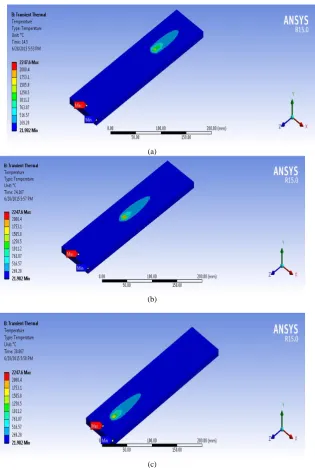
(a)
(b)
(c)
Fig. 2 Longitudinal Residual Stress for different Welding Speeds
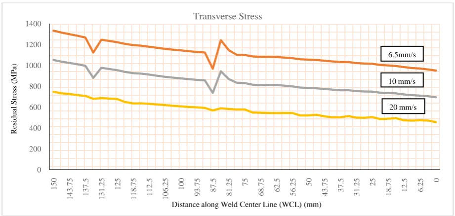
Fig. 3Transverse Residual Stress for different Welding Speeds
From Fig. 2, it is clear that the stress is the maximum on the WCL and gradually decreases thereafter to the end of work piece. Stress after welding is the maximum for weld made at 6.5 mm/s and it is quite reasonable because slower the speed, more will be the heat input and hence more will be the residual stress developed. Weld with a speed of 20 mm/s finishes fast and less total heat is imparted to the work piece resulting in less residual stress. The weld made at the
0 200 400 600 800 1000 1200 0 1 .5 6 2 5 3 .1 2 5 4 .6 8 7 5 6 .2 5 7 .8 1 2 5 9 .3 7 5 1 0 .9 3 7 1 2 .5 1 4 .0 6 2 1 5 .6 2 5 1 7 .1 8 7 1 8 .7 5 2 0 .3 1 2 2 1 .8 7 5 2 3 .4 3 7 25 2 6 .5 6 3 2 8 .1 2 5 2 9 .6 8 7 3 1 .2 5 3 2 .8 1 2 3 4 .3 7 5 3 5 .9 3 8 3 7 .5 R esi d u al S tr ess (M P a)
Distance from Weld Center Line (WCL) (mm)
Longitudinal Stress 6.5 mm/s 10 mm/s 20 mm/s 0 200 400 600 800 1000 1200 1400 150 1 4 3 .7 5 1 3 7 .5 1 3 1 .2 5 125 1 1 8 .7 5 1 1 2 .5 1 0 6 .2 5 100 9 3 .7 5 8 7 .5 8 1 .2 5 75 6 8 .7 5 6 2 .5 5 6 .2 5 50 4 3 .7 5 3 7 .5 3 1 .2 5 25 1 8 .7 5 1 2 .5 6 .2 5 0 Re sid u al S tr ess (MP a )
Distance along Weld Center Line (WCL) (mm) Transverse Stress
6.5mm/s
10 mm/s
moving torch. For the transverse stress also, slower welding leaves behind more residual stress and there seems to be a disturbance at about 87 mm from the beginning end of work piece for all the three cases. Even though the reason for the disturbance could not be understood, it was observed that the amplitude of this disturbance was more for welding with the slowest speed. The fastest welding overlooks this disturbance and maintains a smoother distribution.
IV.CONCLUSION
The following points may be concluded from the study:
(1) Welding speed has an inverse effect on residual stress distribution. The more the welding speeds, the less is the residual stress. This is due to the larger heat input in the case of slow moving welding torch.
(2) In the case of longitudinal residual stress distribution, the steepness of curve is the highest for welding at 20 mm/s and it reduces with welding speed. The higher temperature gradient associated with higher welding speed is cited to be the reason.
(3) Residual stress depends on the size of weld pool also. Slow welding creates large sized weld pool and the lesser rate of cooling makes the curve less steep or more diverging.
(4) Any disturbance in heat flow makes fluctuations in residual stress and its amplitude will be more in the case of slow welding. With higher speed, the peaks are averaged out leading to a smoother curve.
REFERENCES
[1] A.H. Yaghi, D.W.J. Tanner, T.H. Hyde, A.A. Becker, W. Sun, 2011, Abaqus Thermal Analysis of the Fusion Welding ofa P92 Steel Pipe,SIMULIA Customer Conference.
[2] Jodh Singh, Surinder Singh Bhinder, 2014,Effect of Welding Speed on Depth of Penetration DuringArc Welding of Mild Steel Plates,
IJRMET,Vol. 4, Issue 2, Spl- 2 ,May – October.
[3] A. Raveendra1, Dr. B. V. R. Ravi Kumar, Dr.A.Sivakumar,N.santhosh, 2014, Effect of welding parameters on 5052aluminium alloy weldmentsUsing TIG welding, International Journal of Innovative Research in Science, Engineering and Technology,Vol. 3, Issue 3, March, 10302-10309.