Department of Electrical & Electronics Engineering, College of Engineering Perumon, Kollam, Kerala – 691601, India
Review of Efficiency Control of Single Phase
Induction Motor
Rahul M 1, Sindhu V 2
P.G. Student, Department of EEE, Sree Buddha Engineering College, Alappuzha, Kerala, India1
Assistant Professor, Department of EEE, Sree Buddha Engineering College, Alappuzha, Kerala, India2
ABSTRACT: - Power factor correction (PFC) is common in commercial and industrial applications. A need to extend the application of PFC will increased with the dwindling natural resources used for power generation and also exceeding energy demand, hence more efficient power usage and motor system are required at the forefront of utility's demand side management system. The aim is to design and build an active PFC using a boost DC/DC converter and implement it on a single phase induction motor for small industrial and residential applications. However it can be developed to a three phase system for bigger industrial applications. The basic architecture of this will includes a power supply, a rectifier, DC/DC boost converter, an inverter, control circuitry, and a single split phase induction motor. The energy usage of the motor without PFC is recorded and then compared with energy of a motor with PFC. The cost analysis of the two energy usage is compared and the main objective is to realise some savings. This paper discusses system design, influence of the PFC on the system’s power consumption and power factor, comparing the results between two systems, and also cost evaluation.
KEYWORDS:PFC (power factor correction), photovoltaic, DC/DC boost converter, single phase induction motor, inverter.
I. INTRODUCTION
In this paper it describes the improvement of power factor of an induction motor by using capacitor bank. When power factor is improved, then the energy will be saved automatically. The power factor is the goal of any electrical utility company since if the power factor is less than one, then they have to supply more current to the user for a given amount of power use[1]. But in so doing they occur more line losses. Induction motors are the most widely used electrical motors due to their reliability, low cost, low maintenance and robustness. For industrial and mining applications, 3-phase AC induction motors are used as prime movers for the vast majority of machines. It has been estimated that 70% to 80% of all electricity in the world is consumed by these types of motors. At no load condition induction motor has very low power factor. Power factor will improves at increasing load from no load to full load. Power factor correction is achieved by the addition of capacitors in parallel with the connected motor circuits and can be applied at the starter, otherwise it can be applied at the switchboard or distribution panel.
Department of Electrical & Electronics Engineering, College of Engineering Perumon, Kollam, Kerala – 691601, India
but it becomes a problem in industry where multiple large motors are used [2]. Thus the Power factor correction is usually achieved by adding capacitive load to offset the inductive load present in the power system.
II. POWER FACTOR
In an AC circuits there is generally a phase difference between the voltage and current. The term Cosϕ is known as the power factor of the circuit. If the circuit is inductive, then the current is lags behind the voltage and the power factor is called lagging power factor. If the circuit is capacitive then the current leads the voltage and power factor is said to be leading power factor. The average power in an AC circuit is expressed in terms of rms current and voltage, ie P= VI. A. The purely resistive load would have a power factor of 1.0 (unity).
Power factor correction is a technique of counteracting the undesirable effects of electrical loads that create a power factor that is less than one. Power factor correction may be applied either by an electrical power transmission utility to improve the stability. Low power factor is an issue, it can be solved by adding power factor correction capacitors to the plant distribution system.
AC power flow has three components:
Real power or active power (P), expressed in watts (W) Apparent power (S), expressed in volt-amperes (VA)
Reactive power (Q), expressed in reactive volt-amperes (VAR)
The VA and VAR are the non-SI units mathematically identical to the Watt, but are used in engineering practice instead of the Watt in order to state what quantity is being expressed behind it. The power factor is defined as the ratio of real power to apparent power. If the power is transferred along a transmission line, it does not consist purely of real power that can do work once transferred to the load. But it consists of a combination of real and reactive power, called apparent power. The power factor will describes the amount of real power transmitted along a transmission line relative to the total apparent power flowing in the transmission line.
The Power Triangle:
Fig.1 Power Triangle
The various components of AC power can be related by using the power triangle. The real power is extends horizontally in the î direction as it represents a purely real component of AC power. And the apparent power represents a combination of both real and reactive power. Therefore it can be calculated by using the vector sum of these two components. We can conclude that the mathematical relationship between these components as:
S2 = P2 + Q2
Department of Electrical & Electronics Engineering, College of Engineering Perumon, Kollam, Kerala – 691601, India
Cosϕ, power factor = (P, real power / S, apparent power)
POWER FACTOR OF AN INDUCTION MOTOR
The only possible source of excitation in an induction machine is the stator input. The induction motor therefore must be operate at a lagging power factor. The power factor is very low at no load and increases to about 85 to 90 percent at full load in an induction motor. The improvement being caused by the increased real-power requirements with increasing load. The presence of air-gap between the stator and rotor will greatly increases the reluctance of the magnetic circuit of an induction motor. Also an induction motor draws a large magnetizing current (Im) to produce the
required flux in the air-gap.
(i)At no load condition, an induction motor draws a large magnetizing current and a small active component to meet the no-load losses. Thus, the induction motor takes a high no-load current lagging the applied voltage by a large angle. Hence the power factor of an induction motor on no load is very low, it may about 0.1 lagging.
(ii)When an induction motor is at loaded condition, the active component of current will increases while the magnetizing component remains about the same. Also the power factor of the motor is increased. Because of the large value of magnetizing current, which is present regardless of load, the power factor of an induction motor even at full load exceeds 0.9 lagging.
Induction machine may become self-excited when a sufficiently heavy capacitive load is present in their stator circuits. Then the capacitive current furnishes the excitation and cause serious overvoltage or excessive transient torques.
c
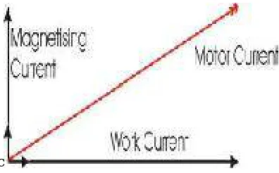
Fig 2. Current components of an induction motor
The magnetizing current is the current that establishes the flux in the iron and it becomes very necessary if the motor is going to operate. The magnetizing current does not contribute to the actual work output of the motor. The magnetizing current and the leakage reactance can be considered as the passenger components of current that will not affect the power drawn by the motor. But it will contribute to the power dissipated in the supply and distribution system.
Department of Electrical & Electronics Engineering, College of Engineering Perumon, Kollam, Kerala – 691601, India
In reducing the losses in the distribution system, power factor correction is added to neutralize a portion of the magnetizing current of the motor. The corrected power factor will be 0.92 - 0.95 some power retailers offer incentives for operating with a power factor of better than 0.9, while others penalize consumers with a poor power factor. The net result is that in order to reduce wasted energy in the distribution system. Thus the consumer will be encouraged to apply power factor correction methods.
DISADVANTAGES OF LOW POWER FACTOR
1.) Large Line Losses (Copper Losses):
The line Losses is directly proportional to the squire of current, Power Loss = I2*R i.e., the larger the current, the greater the line losses i.e. I>>line losses .Power Loss = I2xR = 1/CosФ
2.
. Since I ∝1/CosФ. Thus, if Power factor = 0.8, then losses on this power factor =1/CosФ2 = 1/ 0.82 = 1.56 times will be greater than losses on unity power factor.
2.) Large kVA rating and Size of Electrical Equipment:
Almost all electrical machinery are rated in kVA. But, it is clear from the following formula that power factor is inversely proportional to the kVA i.e. CosФ = kW / kVA. Therefore, the lower the power factor, the larger the kVA rating of machines also, the larger the kVA rating of machines. The larger the Size of machines and the larger the size of machines and the larger the cost of machines.
3.) Greater Conductor Size and Cost:
In case of low power factor, current will be increased, and then to transmit this high current, we need the larger size of conductor. Also, the cost of large size of conductor will be increased.
4.) Poor Voltage Regulation and Large Voltage Drop:
The voltage Drop = V = IZ. In case of low power factor, current will be increased. So the larger the current, the Larger the voltage drop. Also the voltage regulation,V.R = (VNo Load – VFull Load)/ VFull Load. In case of the low power factor there
would be large voltage drop which cause low voltage regulation. Therefore, keeping voltage drop in the particular limit, we need to install Extra regulation equipment.
5.) Low Efficiency:
In the case of low power factor, there would be large voltage drop and large line losses and this will cause the system or equipment efficiency too low. Due to low power factor, there would be large line losses; therefore, alternator needs high excitation.
6.) Penalty from Electric Power Supply Company on Low Power factor:
The electrical power supply company imposes a penalty, for power factor below certain limit, in electric power bill. So power factor should be maintained at a specified value.
III. SIMULATION AND RESULTS
Department of Electrical & Electronics Engineering, College of Engineering Perumon, Kollam, Kerala – 691601, India
Fig.4 Simulink model of induction motor
The following characteristics of the SPIM is Plotted. Current vs. time. Figure 5 shows the total stator current. The stator reactive current changes direction at approximately mechanical power of 3kW as the rotor resistance value is decreased. Furthermore, with the reduction of the rotor resistance, magnitude of the stator reactive current becomes more capacitive (i.e. negative value) implying that reactive power is fed back to the grid.
Fig.5 Rotor current at constant load
From the simulation result the value of current obtained is as shown below
CALCULATION OF LOAD TORQUE
N = 120F/P = 3600
ω= 2ᴨN/60 = 376.99
Load torque = P/ ω = 0.494
CALCULATION OF LOAD CURRENT
Department of Electrical & Electronics Engineering, College of Engineering Perumon, Kollam, Kerala – 691601, India
=110/13.306
=8.26 A
III. CONCLUSION
A review of efficiency improvement of single phase induction motor is conducted. Each individual large consumer should be corrected for practically unity power factor, and to do this the proper synchronous condenser capacity should be introduced at some point in the consumer's line where the most economical results can be obtained. This, however, will vary very largely with each individual consumer and must be studied in each case. The operating single phase induction motor at unity power factor is practically very difficult. When the load on motor changes, it may result in under or over correction of power factor.
REFERENCES
[1] B.A. Mather, D. Maksimovi, “A simple digital power factor correction rectifier controller,” IEEE Trans. Power Electronics, vol. 26, no. 1, pp. 9-19, Jan. 2011.
[2] S. B. Monge, J. C. Crebier, S. Ragon, E.Hertz, D. Boroyevich, Z. Gurdal, M. Arpilliere, and D. K. Lindner, “Design of a boost power factor correction converter using optimization techniques,” IEEE Trans. Power Electronics, vol. 19, no. 6, pp. 1388-1396, Jan. 2004.
[3] On semiconductor ® “Power factor correction (PFC) Handbook,” HBD 853/D Revision 4, February 2011.
[4] H. Huang, E. F. Fuchs, and J. C. White, “Optimal placement of the run capacitor in single-phase induction motor designs,” IEEE Trans. Energy Convers., vol. 3, no. 3, pp. 647–652, Sep. 1988.
[5] K. Sundarareswaran, “An improved energy-saving scheme for capacitor-run induction motor,” IEEE Trans. Ind. Electron., vol. 48, no. 1, pp. 238–240, Feb. 2001.
[6] Sharkawi E l,Chen M A, Vandari S V, Fisser G W, Butter N G, Vinger R J,“An Adaptive Power Factor Controller for Three Phase Induction Generator”,IEEE Transaction on Power Apparatus and Systems,,Volume PAS 104,PP.1825-1831,1985.
[7] Sharkawi E l,Chen M A, Vandari S V, Fisser G W, Butter N G, Vinger R J,“Develpoement and Field Tasting of A Closed Loop Adaptive Power Factor Controller”, IEEE Transaction on Energy Concession, Volume 3,PP.235-240,1998.
[8] Marlar Thein Oo, Ei Ei Cho, “Proceedings of World Academy of Science,Engineering and Technology”, ISSN, Volume 32, PP.2070-3740, 2008. [9] Al Ali, Negan A R, Kassas M M, “A PLC Based Power Factor Controller forA 3 Phase Induction Motor”, IEEE Conference on Industry
Applications, Volume: 2, PP.1065-1072, 2000.
[10] Ayres,Barbi C A, “ CCM Operation Analysis of A Family of Converter forPower Recycling During the Burn-in Test of Synchronized UPSs”, IEEE Conferences on Power Electronics Specialist, Volume 2,PP. 986-992,1996.
[11] Nalbant M K, “Power Factor Calculations and Measurement”, IEEE Conferences on Applied Power Electronics, PP.453-553,1990. [12] Rakendu Mandal, Sanjoy Kumar Basu, Asim Kar,Syama Pada, “A Microcomputer Based Power Factor Controller”, IEEE Transaction on
Industrial Electronics, Volume 41,PP.361-671,1994.
[13] Sharaf AM and Huang H, “Nonlinear Load Reactive Compensation and PowerFactor Correction Using Modulated Power Filter”.