ISSN(Online): 2320-9801
ISSN (Print): 2320-9798
I
nternational
J
ournal of
I
nnovative
R
esearch in
C
omputer
and
C
ommunication
E
ngineering
(An ISO 3297: 2007 Certified Organization)
Vol. 3, Issue 6, June 2015
Automatic Intrusion Recognition, Tracking
and Destruction for Security Systems
Rupali N. Wadekar, Dr. M. S. Nagmode
PG Student, Dept. of E&TC, MITCOE, Pune, India
Professor, Dept. of E&TC, MITCOE, Pune, India
ABSTRACT: Areas which are very sensitive regarding unwanted harmful activities need an efficient security system. Such security system should be capable of identifying the intruding objects successfully. If such systems are capable of tracking and destroying the intruding objects, there will be no need to appoint human soldiers in sensitive areas. This paper proposes a system that automatically recognizes tracks and destroys the intruding object in the area under surveillance. System is rotation as well as scale invariant. SIFT has been included to make the system illumination invariant. Though SIFT increases the computational time and complexity, high recognition accuracy is obtained. Thus, such a system will ensure tight security without endangering the precious life of human soldiers. The system proposed here is a complete independent system in which camera, image processing software, supplementary hardware takes care of destroying intruding objects automatically. Total 10 objects of different sizes and shape are tested. From experimental results it is found that system gives good performance for various shapes and sizes. Overall recognition accuracy is 95%.
KEYWORDS: Illumination invariant; rotation invariant; scale invariant; SIFT. I. INTRODUCTION
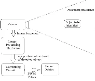
The system is proposed for detecting, tracking and destroying intruding objects. System is provided with a camera which is mounted at suitable place from where a complete view of area under interest can be obtained. In order to have better results, it should be made sure that the camera does not move at all from its initial position. Otherwise it will affect the recognition accuracy. Images obtained from camera are given to image processing software. This software processes the images to extract the features of the detected object. Features of database object are stored prior to that of detected object. Then, features of database object and detected object are compared to decide whether the detected object is intruding one. If so, x-y position of this object is sent to microcontroller which provides PWM pulses to servo motor. Depending on the width of PWM pulses, angle of rotation of servo motor is controlled. On servo motor, cannon is placed, which gets fired if intrusion is detected. The system tracks the object until it gets completely destroyed. Following figure, Fig. 1 shows block diagram of complete system.
II. RELATED WORK
This section of paper describes the work that has been done in the area of video surveillance systems, different approaches followed for better results in object recognition and tracking. Researchers have attempted to develop a complete independent system for detecting an intrusion and tracking it until it gets destroyed using image processing algorithm, microcontroller, servo motors and other supplementary hardware [1], [2]. Shape and color of an object is extracted and compared with database object to decide whether it is intruding one. Canny edge detection algorithm has been used and PWM pulses are used to adjust rotation of servo motor. Satisfactory results are obtained in experimentation.
ISSN(Online): 2320-9801
ISSN (Print): 2320-9798
I
nternational
J
ournal of
I
nnovative
R
esearch in
C
omputer
and
C
ommunication
E
ngineering
(An ISO 3297: 2007 Certified Organization)
Vol. 3, Issue 6, June 2015
offices, shopping malls or traffic highways. Tracking of pedestrians and vehicles play the key role in video surveillance systems. Dimensions of bounding box are used to distinguish between pedestrians and vehicles.
Fig. 1 Block diagram of a complete system
YigithanDedeoglu [4] has presented a smart visual surveillance system which is capable of moving object detection in real-time, classification and tracking. The system has a stationary camera; system is capable of operating on color as well as gray scale video. An adaptive background subtraction scheme is used for moving object detection which is found to work reliably in indoor as well as outdoor environments. Temporal differencing and adaptive background mixture models are the two other object detection schemes, proposed for detection and performance quality comparison. The proposed system is able to perform functions like distinguishing transitory and stopped foreground removed objects; classifying detected objects into various groups such as vehicle, human and human group; tracking objects and generating trajectory information in multi-occlusion cases and detecting fire in video imagery. This system is assumed to work in real time. And for real time performance, the computational complexity and the constant factors of the algorithms used are important. Use of this system is restricted to stationary cameras and video inputs obtained from Pan/Tilt/Zoom cameras. The initial input to this system is fed from video imagery from a static camera which is monitoring a required site. Most of the methods are able to work on both color and monochrome video imagery.
ISSN(Online): 2320-9801
ISSN (Print): 2320-9798
I
nternational
J
ournal of
I
nnovative
R
esearch in
C
omputer
and
C
ommunication
E
ngineering
(An ISO 3297: 2007 Certified Organization)
Vol. 3, Issue 6, June 2015
System can be made more efficient if it is made illumination invariant. A popular method used for appearance and illumination invariant human detection is Histogram of Oriented Gradients (HOG) detector [17]. To recognize the objects on different scales Scale invariant feature transform (SIFT) [18] based method is used. S. Nigam, M. Khare, R.K. Srivastava, and A. Khare proposed a hybrid of HOG and SIFT methods [19] for human object detection.
III.METHODOLOGY
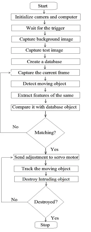
Working of the system is explained using flowchart as shown in Fig. 2.
A. Camera:
Camera used for experimentation is Zebion web camera with 1.3 Mega Pixel interpolated resolution, high quality 5G wide angle lens, 6 auto lighting LEDs for night vision, snapshot button for still image capture, compliance with USB 2.0, video resolution of 800 x 600 pixels and image resolution of 640x480, 800x600, 1280x1024 pixels. It is mounted at suitable place from where a complete view of area under interest can be obtained. It is very much necessary that camera should not move from its initial position. Otherwise it will adversely affect the recognition accuracy since every frame of video is subtracted from background. Thus due to change in background results will also change. Video frames are given to the computer with MATLAB code. A Night-Vision Camera and camera with different resolution and colour depth can be used depending upon requirement of application.
B. Image Processing:
A computer with Intel 1.6 GHz processor and 512MB RAM is used as Image Processing hardware. Camera is connected to this PC via USB port. MATLAB is used as image processing software. Image frames captured by camera are given to this software. It processes these images for feature extraction.
Pre-processing:
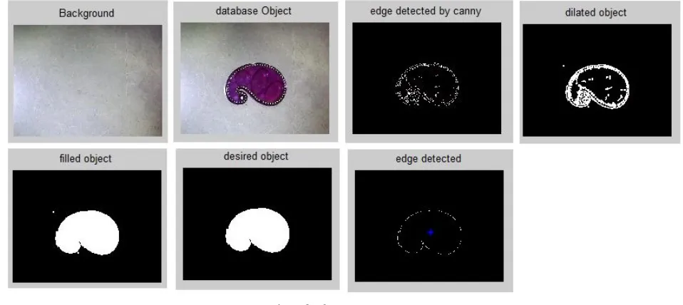
When an object is observed from a far distance, its colour and shape distinguish it from other objects and background. Therefore it is necessary to first separate the object from background and other objects. To do this, background subtraction method is used. Once the result of subtraction is available, edge of an object is detected using canny edge detection algorithm. But the edges of the object are unclear and broken. To overcome this problem, image is dilated with some suitable mask. Holes in binary images are black portion of image surrounded by white boundary. These holes are filled with filling operation to get number of different unconnected white areas. These white areas arerelated to different objects in image. At this stage, we get a number of white regions. These unwanted regions are due to illumination variation, camera imperfections and minor changes in the background while capturing images. Since we are interested in only intruding object, we need to select only the corresponding region. The area of unwanted white regions is smaller than the white region corresponding to intruding object. Thus, if we select only the white region with maximum area, we get intended object. Edge of this image is detected using canny edge detection method. After this step, we get a clear edge of an object.
Feature Extraction:
In this system, shape, colour and SIFT key points of an object are extracted. a) Shape:
In order to save shape descriptor of an object, we need to calculate distance of all points on its edge from some arbitrary point; this point is taken as centroid of an object. In this case, distances of points on the edge are taken at the angles with interval of 10 degrees from centroid. Thus 36 different distances are stored in shape descriptor of an object.To increase the accuracy, we can increase the number of distances by decreasing the interval of angle, but this will increase the computation time.
ISSN(Online): 2320-9801
ISSN (Print): 2320-9798
I
nternational
J
ournal of
I
nnovative
R
esearch in
C
omputer
and
C
ommunication
E
ngineering
(An ISO 3297: 2007 Certified Organization)
Vol. 3, Issue 6, June 2015
means dividing each distance from the maximum distance available in the descriptor. This brings all readings of shapedescriptor in the range of 0-1. 1 corresponds to the maximum distance. Thus, scale invariance is achieved. If an object is rotated, it should be correctly identified by the software. To do this circular shifting of readings is done. Thus, rotation invariance is achieved.
Fig. 2 Flowchart of working of the system b) Colour:
ISSN(Online): 2320-9801
ISSN (Print): 2320-9798
I
nternational
J
ournal of
I
nnovative
R
esearch in
C
omputer
and
C
ommunication
E
ngineering
(An ISO 3297: 2007 Certified Organization)
Vol. 3, Issue 6, June 2015
E.g. red, green and blue colours can be distinguished as in HSV plane as: Red pixels have values >0.8 and <0.15, Green pixels have values >0.15 but <0.48, Blue pixels have values >0.48 but <0.8.Thus second gross feature of the objects that is its colour is detected.
Scale Invariant Feature Transform (SIFT):
In addition to shape and colour, SIFT (Scale Invariant Feature Transform) key- points are used to describe the object. SIFT is robust to illumination variations. It is patented algorithm, therefore not freely available. Hence, SIFT executable is used in this system. Feature extraction is also performed on database object. Comparison of features of detected image and database object is done. If results match, the detected object is considered as an intruding object which needs to be destroyed.
Following are the main steps in evaluating SIFT key points [18]: 1) Detection of scale-space extrema:
In this step, potential interest points are identified using difference-of-Gaussian function. These points are scale and pose invariant. Scale space of an image is defined as:
( , , ) = ( , , ) ∗ ( , )
eq. (1) Where ( , , ) is variable scale Gaussian and ( , ) is an input image,∗denotes the convolution operation.
( , , )is given by,
( , , ) = 1 2
( )/
eq. (2) To efficiently detect stable key points, Difference-of-Gaussians (DOG) is used which is computed by difference of two nearby scales separated by constant multiplication factor k.
( , , ) = ( , , )− ( , , ) ∗ ( , )
= ( , , )− ( , )
eq. (3) Thus D can be computed by simple image subtraction. Construction of ( , , ) can be efficiently done as shown in Fig. 3.The initial image is incrementally convolved with Gaussians to produce images separated by a constant factork in scale space. Then each octave of scale space is divided into an integer number s such that = 2 . Adjacent image scales are subtracted to produce the difference-of-Gaussian images.Once a complete octave has been processed, the Gaussian image is resampled that has twice the initial value of σ by taking every second pixel in each row and column. Local maxima and minima of ( , , )is calculated by comparing each sample point with its eight neighbours in the current image. At the same time each sample point is also compared with its nine neighbours in the image above and below it. If this point is either larger or smaller than all these neighbouring points, then only it is selected.
2) Localization of accurate key points:
At this stage, key points are selected depending on their stability. For stability, key points with low contrast are rejected.
3) Orientation assignment:
In this step, gradient magnitude ( , ) and orientation ( , ) are computed for each sample using pixel differences.
( , ) = ( ( + 1, )− ( −1, )) + ( ( , + 1)− ( , −1)) ( , ) = ( ( , + 1)− ( , −1) ⁄(( ( + 1, )− ( −1, ))
eq. (4) An orientation histogram is formed from the gradient orientations of sample points within a region around the key point. The highest peak in the histogram is detected.
4) Key point descriptor:
ISSN(Online): 2320-9801
ISSN (Print): 2320-9798
I
nternational
J
ournal of
I
nnovative
R
esearch in
C
omputer
and
C
ommunication
E
ngineering
(An ISO 3297: 2007 Certified Organization)
Vol. 3, Issue 6, June 2015
into orientation histograms summarizing the contents over 4x4 sub-regionswith the length of each arrow corresponding to the sum of the gradient magnitudes near that direction within the region.
Fig. 3 (a) and (b) Process of detecting scale space extrema, (c) Process of generating key-point descriptor [18]
C. Controlling Circuit:
Microcontroller is used as controlling circuit. x-y position of the intruding object is sent to microcontroller. Microcontroller is interfaced with computer using serial cable. MAX232 IC is used to convert RS232 standard level signal to TTL logic level. Microcontroller is used to send PWM pulses to servo motor. Angle of rotation of servo motor is changed according to the width of PWM pulses applied to it. Microcontroller used is 89V51RD2 which has 80C51 Central Processing Unit, operating frequency from 0 MHz to 40 MHz, 64 kB of on-chip Flash user code memory.
D. Servo Motor
Servo motor decides the angle of projection of cannon. The results obtained after Image Processing are fed to microcontroller which in turn controls firing angle and time for projectile launch.
IV.EXPERIMENTATION AND RESULTS
ISSN(Online): 2320-9801
ISSN (Print): 2320-9798
I
nternational
J
ournal of
I
nnovative
R
esearch in
C
omputer
and
C
ommunication
E
ngineering
(An ISO 3297: 2007 Certified Organization)
Vol. 3, Issue 6, June 2015
said to be recognized. If number of readings used for shape description is increased, then it drastically improves accuracy. More readings are taken, more accurately shape of the object can be described. Inclusion of SIFT has improved the accuracy. At the same time, computation time and complexity is increased. So, this system is useful in applications where high accuracy is needed.
Thus by implementing this automatic system one can ensure complete intrusion free area under surveillance. This system has great application for military purpose. System eliminates need of human soldier to be appointed for this danger work, as this work is done by this system automatically. Fig. 4 gives result of pre-processing for one of the test objects used in experiments. In this figure, results for dilation, filling, selection of maximum area, detected edge and centroid are shown.
Fig. 4 Result of pre-processing
Table I gives experimental results for 5 different objects. It gives recognition accuracy, feature extraction time, matching time for recognition with SIFT and without SIFT. Table shows that though processing time with SIFT is greater, recognition accuracy is improved.
Table I
Experimentation results
Sr.
No. Object
No. of trials taken
No. of correct recognition
results
Recognition accuracy
(%)
Feature extraction time
(sec)
Matching time (sec)
Total time (sec) Without SIFT
1 Object 1 80 74 93 1.02 1.38 2.4
2 Object 2 80 75 94 0.88 1.56 2.44
3 Object 3 80 74 93 0.91 1.56 2.47
4 Object 4 80 74 93 0.89 1.53 2.45
5 Object 5 80 75 94 0.91 1.54 2.45
With SIFT
1 Object 1 80 77 96 1.19 2.55 3.74
2 Object 2 80 76 95 0.86 2.61 3.47
3 Object 3 80 76 95 0.84 2.76 3.6
4 Object 4 80 76 95 0.85 2.83 3.68
ISSN(Online): 2320-9801
ISSN (Print): 2320-9798
I
nternational
J
ournal of
I
nnovative
R
esearch in
C
omputer
and
C
ommunication
E
ngineering
(An ISO 3297: 2007 Certified Organization)
Vol. 3, Issue 6, June 2015
V. CONCLUSION
The system proposed in this paper is very useful for military applications where it is needed to detect and track the intruding object in the area under surveillance. A simple system is implemented which automatically detects and tracks the intruding object until it is destroyed completely. This system avoids need of appointing human soldiers in entry restricted area where a very tight security is needed. Thus, precious life of human soldiers is taken care of. The system is rotation as well as scale invariant.
REFERENCES
1. Amit Kenjale, “Automatic Object Recognition, Tracking and Destruction for Military Application”, World Congress on Information and Communication Technologies, pp. 1485-1489, 2013.
2. Archana R. Borse and Dilip S. Patil, “Visual Object Recognition, Tracking and Control for Automated Video Surveillance System”, International Journal of Latest Research in Science and Technology, vol. 2, Issue 6, pp. 77-80, November-December 2013.
3. “Object Classification and Tracking in Video Serveillance” by Qi Zang and ReinhardKletteg.
4. “Moving Object Detection, Tracking and Classification for Smart Video Surveillance” By YigithanDedeoglu.
5. Diplaros A., Gevers T., Patras I., “Combining Color and Shape Information for Illumination-viewpoint Invariant Object Recognition”, IEEE Transactions on Image Processing, vol. 15, Issue: 1, Jan. 2006.
6. SanketRege, RajendraMemane, MihirPhatak, Parag Agarwal, “2D Geometric Shape and Color Recognition using Digital Image Processing”, International Journal of Advanced Research in Electrical, Electronics and Instrumentation Engineering, Vol. 2, Issue 6,pp. 2479-2487, June 2013.
7. Shih-Chia Huang and Bo-Hao Chen, “Highly Accurate Moving Object Detection in Variable Bit Rate Video Based Traffic Monitoring Systems”, IEEE Transactions on Neural Networks and Learning Systems, Vol. 24, No. 12, December 2013.
8. M. Hagedoorn, “Pattern Matching Using Similarity Measures”, PhD thesis, Universiteit Utrecht, 2000. 9. R. C. Veltkamp and M. Hagedoorn, “State of the Art in Shape Matching”, Technical Report, Utrecht, 1999.
10. G. Scott and H. Longuet-Higgins, “An Algorithm for Associating the Features of Two Images”, Proceedings Royal Society London, vol. 244, pp. 21-26, 1991.
11. D. Sharvit, J. Chan, H. Tek, and B. Kimia, “Symmetry-Based Indexing of Image Databases”, Journal of Visual Communication and Image Representation, vol. 9, no. 4, pp. 366-380, Dec. 1998.
12. Shalinee Patel, Pinal Trivedi, and Vrundali Gandhi, “2D Basic Shape Detection Using Region Properties”, International Journal of Engineering Research and Technology, vol. 2, no. 5, pp. 1147-1153, May 2013.
13. Himani S. Parekh, Darshak G. Thakore, Udesang K. Jaliya, “A Survey On Object Detection And Tracking Methods”, International Journal Of Innovative Research In Computer And Communication Engineering, Feb 2014.
14. Swati Nigam, Kaushik Deb and Ashish Khare, “Moment Invariants based Object Recognition for Different Pose And Appearances in Real Scenes”, supported in part by Council of Scientific and Industrial Research, Human Resource Development Group, IEEE, 2013.
15. Y. Zhao, and S. Belkasim, “Multiresolution Fourier descriptors for multiresolution shape analysis”, IEEE Signal Processing Letters, vol. 19, no. 10, October 2012.
16. M. Hu, ”Visual pattern recognition by moment invariants”, IRE Transactions on Information Theory IT, vol. 8, pp. 179-187, 1962. 17. N. Dalal, and B. Triggs, “Histogram of oriented gradients for human detection”, CVPR, pp. 886-893, 2005.
18. D. lowe, “Object recognition from local scale invariant features”, ICCV, 1999.
19. S. Nigam, M. Khare, R.K. Srivastava and A. Khare, “An effective local feature descriptor for object detection in real scenes”, IEEE Conference on Information and Communication Technologies, 2013.
BIOGRAPHY
Rupali N. Wadekar has completed her B.E. in E&TC Engineering from MIT College of Engineering, Pune and currently pursuing M.E in VLSI & Embedded System from MIT College of Engineering, Pune. Her research interests include image processing and embedded systems.
![Fig. 3 (a) and (b) Process of detecting scale space extrema, (c) Process of generating key-point descriptor [18]](https://thumb-us.123doks.com/thumbv2/123dok_us/1484884.1181673/6.595.81.484.215.561/process-detecting-scale-space-extrema-process-generating-descriptor.webp)