University of Windsor University of Windsor
Scholarship at UWindsor
Scholarship at UWindsor
Electronic Theses and Dissertations Theses, Dissertations, and Major Papers
1-1-1980
Single-crossarm stayed column with initial imperfections.
Single-crossarm stayed column with initial imperfections.
Kevin Chi-Yuen Wong
University of Windsor
Follow this and additional works at: https://scholar.uwindsor.ca/etd
Recommended Citation Recommended Citation
Wong, Kevin Chi-Yuen, "Single-crossarm stayed column with initial imperfections." (1980). Electronic Theses and Dissertations. 6753.
https://scholar.uwindsor.ca/etd/6753
This online database contains the full-text of PhD dissertations and Masters’ theses of University of Windsor students from 1954 forward. These documents are made available for personal study and research purposes only, in accordance with the Canadian Copyright Act and the Creative Commons license—CC BY-NC-ND (Attribution, Non-Commercial, No Derivative Works). Under this license, works must always be attributed to the copyright holder (original author), cannot be used for any commercial purposes, and may not be altered. Any other use would require the permission of the copyright holder. Students may inquire about withdrawing their dissertation and/or thesis from this database. For additional inquiries, please contact the repository administrator via email
SINGLE-CROSSARM STAYED COLUMN WITH INITIAL IMPERFECTIONS
by
Kevin Chi-Yuen Wong
A Thesis
submitted to the Faculty o f Graduate Studies through the Department of
Civil Engineering in Partial Fulfillment of the requirements for the Degree
o f Master o f Applied Science at The University of Windsor
Windsor, Ontario, Canada
U M I Number: E C 5 47 3 6
IN FO RM A TIO N T O USERS
The quality of this reproduction is dependent upon the quality of the copy
submitted. Broken or indistinct print, colored or poor quality illustrations
and photographs, print bleed-through, substandard margins, and improper
alignment can adversely affect reproduction.
In the unlikely event that the author did not send a complete manuscript
and there are missing pages, these will be noted. Also, if unauthorized
copyright material had to be removed, a note will indicate the deletion.
UMI Microform E C 5 4 7 3 6 Copyright 2010 by ProQuest LLC
All rights reserved. This microform edition is protected against unauthorized copying under Title 17, United States Code.
ProQuest LLC
789 East Eisenhower Parkway P.O. Box 1346
Ann Arbor, Ml 48106-1346
TO MY FAMILY
ABSTRACT
SINGLE-CROSSARM STAYED COLUMN WITH INITIAL IMPERFECTIONS
by
Kevin Chi-Yuen Wong
The elastic buckling strength of a concentrically loaded,
pin-ended, slender metal column may be increased many times by reinforcing
it with an assemblage of rigidly connected crossarm members and
pre-tensioned stays.
The presence of an initial out-of-straightness has an effect on
the strength on the stayed column. This thesis deals with the
stability analysis of the imperfect plane single-crossarm stayed
column. The effect of pretensioned stays on the buckling strength of
the imperfect stayed column is derived. A geometrical study provides
the relationship between the applied load, deflections and tension in
the stays. The geometrical nonlinear behavior is included in the
analysis by using the finite element method. Such an analysis is
carried out by a mixed incremental and iterative procedure, is pro
grammed in FORTRAN IV Language and is run on an IBM/360 system.
A plane imperfect stayed column was used in a series of
experimental tests. The experimental buckling loads obtained with
various initial pretensions were compared with those theoretically
predicted. The results of a nonlinear analysis on the imperfect
stayed column shows good agreement with the experimental results.
These results also indicate that the presence of an initial out-of
straightness significantly reduces the buckling strength and that the
type of initial out-of-straightness has a great effect on the mode of
A C K N O W L E D G E M E N T S
The author wishes to express his sincere gratitude to his thesis
advisor, Dr. M. C. Temple, for his encouragement, advice and valuable
suggestions throughout the preparation of this thesis.
Thanks are due t o :
the National Research Council whose financial assistance made this
research possible;
the Computer Centre at the University of Windsor for running the
computer program;
the structural engineering staff members for their valuable advice
the technicians of the Civil Engineering laboratory for their
assistance in the preparation of the model.
v
T A B L E O F C O N T E N T S
ABSTRACT ... iv
ACKNOWLEDGEMENTS ... v
LIST OF ILLUSTRATIONS ... ix
LIST OF TABLES ... xii
LIST OF ABB RE VIATIONS ... xiii
CHAPTER 1 INTRODUCTION ... 1
1.1 General 1 1.2 Previous Method of Study 1 1.3 The System and Purposes to be Studied 3 2 LITERATURE SURVEY ... 4
3 ANALYTICAL STUDY OF STAYED COLUMN ... 8
3.1 General 8 3.2 Ideal Stayed Column 9 3.2.1 Assumptions for an Ideal Stayed Column 9 3.2.2 Basic Definitions of Pretension Applicable to an Ideal Stayed Column 10 3.2.3 Geometric Analysis for an Ideal Stayed Column 11 3.3 Real Stayed Column 15 3.3.1 Assumptions for a Real Stayed Column 16 3.3.2 Definitions of Pretension Applicable to a Real Stayed Column 16 3.3.3 Geometric Analysis for a Real Stayed Column 18 3.4 Geometrical Nonlinear Analysis 21 3.4.1 General 21 3.4.2 General Techniques for Solving Nonlinear Equations 23 (a) Iterative Procedure 24 (b) Incremental Procedure 25 (c) Mixed Procedure 26 3.4.3 Solutions for the Nonlinear Behavior of the Real Stayed Column 27 4 COMPUTER SOLUTION ... 30
4.1 General 30
4.2 Description of the Computer Program 30
4.2.1 Main Program 31
4.2.2 Subroutines 33
4.3 The Advantages and Limitations of the
C H A P T E R
5 EFFECT OF STAYED COLUMN PARAMETERS ... 35
5.1 General 35
5.2 The Basic Parameters 35
5.3 Effect of End Support Condition 36
5.4 Effect of Initial Out-of-Straightness
(Imperfection) 38
5.4.1 Type of Initial Imperfection 38
5.5 Effect of Length of Crossarm 40
5.6 Effect of Stay Size 43
5.7 Effect of Modulus of Elasticity of Stay 44
5.8 Numerical Example 44
5.8.1 Buckling Strength versus Various
Crossarm Length 45
5.8.2 Buckling Strength versus Various
Stay Size 47
5.8.3 Buckling Strength versus Various
Moduli of Elasticity of Stay 49
5.9 Effect of Initial Imperfection on the
Lateral Deflection Rate 50
5.10 Effect of Initial Imperfection on the Change
in Stay Tension 51
5.11 Effect of Initial Stay Pretension on the
Lateral Deflection Rate 53
5.12 The Buckling Strength versus the Initial
Stay Pretension of the Stayed Column 54
5.13 Numbers of Effective Stays as Related to
the Initial Imperfection 56
6 EXPERIMENTAL RESULTS ... 57
6.1 General 57
6.2 The Model of Stayed Column 57
6.2.1 Type of Model 57
6.2.2 Components of the Stayed Column 57
6.2.3 The Dimensions of the Model 59
6.3 Experimental Equipment and Set-Up 60
6.4 Experimental Procedure 62
7 ANALYSIS OF RESULTS ... 64
7.1 General 64
7.2 Comparison of the Observed Stay Tension
and the Predicted Results 64
7.3 Comparison of the Observed and the Predicted
Deflected Shape of the Real Stayed Column 66
7.4 Comparison of the Observed and the Predicted
Buckling Loads as the Initial Pretension is
Varied 66
7.5 Comparison of the Experimental and the
Theoretical Change in Stay Tension 67
vii
C H A P T E R
8 CONCLUSIONS AND RECOMMENDATIONS ... 69
8.1 General 69 8.2 Conclusions 69 8.3 Future Research 72 ILLUSTRATIONS ... 73
TABLES ... 120
APPENDIX A Generation of the Nonlinear Load-Displacement Relationship of a Two-Dimensional Structure ... 122
APPENDIX B A Flow Chart for the Solution of the Nonlinear Behavior of the Stayed Column ... 128
APPENDIX C Listing of the Computer Program ... 130
BIBLIOGRAPHY ... 141
L I S T O F I L L U S T R A T I O N S Figure 1.1 3.1 3.2 3.3 3.4 3.5 3.6 3.7 3.8 3.9 3.10 3.11 3.12 5.1 5.2 5.3 5.4 5.5
Examples of Stayed Column
General Relationship between Critical Load and Initial Pretension of an Ideal Stayed Column
Equilibrium Force System for an Ideal Stayed Column
Change in Length of Stays due to Axial Deformation
Change in Length of Stays due to Lateral Deformation
Total Deformation of a Real Stayed Column
Equilibrium Force System for a Real Stayed Column
Schematic Diagram of Tangent Stiffness Method
Schematic Diagram of Secant Stiffness Method
Schematic Diagram of Incremental Method
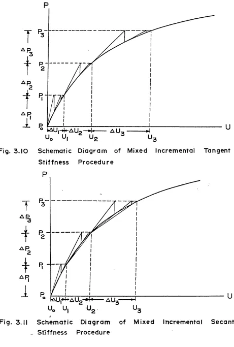
Schematic Diagram of Mixed Incremental Tangent Stiffness Procedure
Schematic Diagram of Mixed Incremental Secant Stiffness Procedure
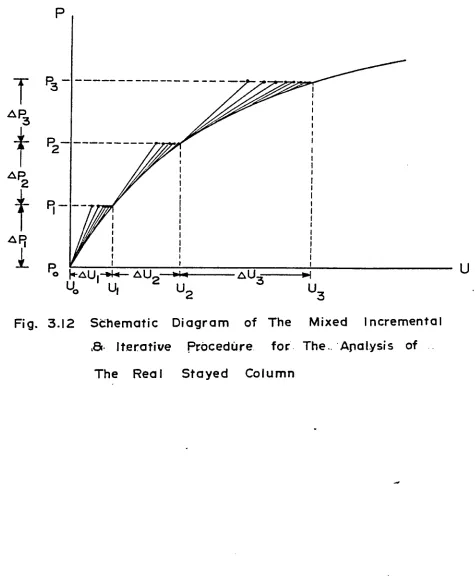
Schematic Diagram of the Mixed Incremental and Iterative Procedure for the Analysis of the Real Stayed Column
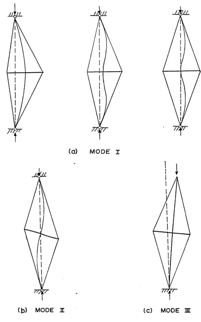
Modes of Buckling Influenced b y End Support Condition
Types of Initial Imperfection and Deflection Shapes
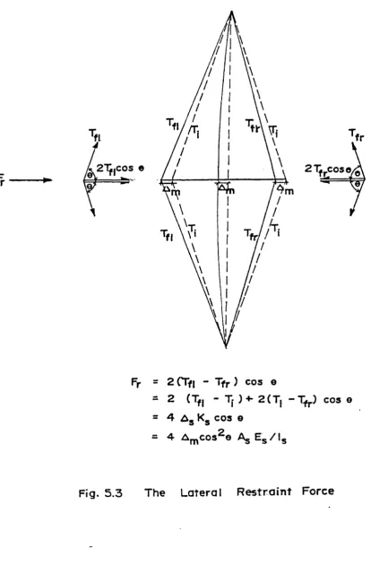
The Lateral Restraint Force
Theoretical Results of the Buckling Load versus the Half Column Length to Crossarm Length Ratio of the Ideal and Real Single-Crossarm Stayed Column with <j> = 3/16" and E = 29,600 ksi
s
Theoretical Results of the Buckling Load versus the Stay Diameter of the Ideal and Real Single-Crossarm
Stayed Column with 2,/fi, = 5 and E = 29,600 ksi
ca s
ix Page 73 74 75 76 76 77 78 79 79 80 81 81 82 83 85 86 87 88
5.6 5.7 5.8 5.9 5.10 5.11 5.12 6.1 6.2 6.3 6.4 6.5 6.6 6.7 6.8 6.9 6.10 6.11 6.12(a) 6.12(b)
Theoretical Results of the Buckling Load versus the Modulus of Elasticity of the Stay of the Ideal and Real Single-Crossarm Stayed Column with
<}> * 3/16" and E = 29,600 ksi 89
s
The Deflection Rate Influenced by Initial Imperfection 90
Change in Stay Tension versus Applied Load of an
Ideal and a Real Stayed Column with = 3/16",
Z/Z = 5 and E = 29,600 ksi 91
ca s
The Deflection Rate Influenced by the Initial
Pretension of a Real Single-Crossarm Stayed Column
with <J> = 3/16", Z/Z = 5 and E = 29,600 ksi 92
ca s
The Deflection Rate Influenced by the Initial
Pretension of a Real Single-Crossarm Stayed Column
with cj> = 3/16", Z/Z = 5 and E = 29,600 ksi 93
ca s
Theoretical Result of Buckling Load versus Various
Initial Pretension o f an Ideal and Two Real Stayed
Columns with <f> = 3/16", Z/Z = 5 and E = 29,600 ksi 94
ca s
Numbers of Effective Stays due to Various Types of
Initial Imperfection 95
Model of Stayed Column 96
Circular Steel Tube of Crossarm and Core 97
Connection Between Crossarm and Core 98
Connection Between Crossarm and Stay 98
Bottom Support 99
Lateral Support 99
Device for Preventing Rotational Movement 100
Screw Type Load Cell 100
Connection Between Load Cell and Stay 101
Hydraulic Jack and Universal Flat Load Cell 102
Strain Indicator 103
Transit 104
6.13 Device for Measuring Lateral Deformation 106
7.1 Experimental and Theoretical Results of Load
versus Deflection and Tension in Stays for a
Real Stayed Column with 200 lbs. initial pretension 107
7.2 " . 300 lbs. " 108
7.3 " 400 lbs. " 109
7.4 " 500 lbs. " 110
7.5 " 600 lbs. " 111
7.6 '• 700 lbs. " 112
7.7 " 800 lbs. " 113
7.8 Experimental Results of Load versus Deflection for
a Real Stayed Column with Different Initial Pretension 114
7.9 The Deflection Shape of a Real Stayed Column with
600 lbs. Initial Pretension 115
7.10 700 lbs. " " 116
7.11 800 lbs. " " 117
7.12 Experimental and Theoretical Results of Buckling Load
versus Initial Pretension for a Real Single-Crossarm
Stayed Column 118
7.13 Experimental Measured and Calculated Stay Tension
of a Real Stayed Column with 600 lbs. Initial
Pretension 119
xi
L I S T O F T A B L E S
Table
7.1 Results o f Initial Rate of Change in
Stay Tension
7.2 Results of Residual Stay Tension
7.3 Results of Buckling Load, Minimum
Effective, Optimum and Maximum Possible Pretension
Page
120
120
L I S T O F A B B R E V IA T I O N S
English Letters
A ' : cross-sectional area of core
c
A : cross-sectional area of crossarm
CcL
A : cross-sectional area of stay
s
[A] : assembly control matrix
: constant which relates to the optimum pretension and
and maximum critical load
E : modulus of elasticity
E c : modulus of elasticity- of core
E : modulus of elasticity of crossarm
Ca
'E s : modulus of elasticity of stay
E^ : component force of initial pretension acting on the
ends of crossarm
Fr : lateral restraint force
{E} : force matrix of the structure
{E} : force matrix of element in the local coordinate system
G : modulus of rigidity
1 : moment of inertia
K : effective length factor
K c : axial stiffness of core
K ca : axial stiffness of crossarm
K s : axial stiffness of stay
tK] : linear elastic stiffness matrix
: master elastic stiffness matrix
tK G 3 : master geometric stiffness matrix
tK G ] : master geometric stiffness matrix for a unit
internal force
X I 1 1
[Kg^cJ : secant stiffness matrix
[K^] : total nonlinear stiffness matrix
[KT a n ] : tangent stiffness matrix
[k] : total stiffness matrix for element
[kg] : elastic stiffness matrix for element in global
coordinate system
[kg] : elastic stiffness matrix for element in local
coordinate system
: geometric stiffness matrix for element in global
coordinate system
[kg] ; geometric stiffness matrix for element in local
coordinate system
L : length of column
1 : length o f half column
lca : length o f crossarm
1 s : length of stay
^1' m i : direction cosine in x-direction
m 2 : direction cosine in y-direction
P_ : applied axial force
a,
P_„ „ : maximum critical load
cr,max
P^ or P : Euler critical load
E Euler
: final axial force
P^ or P^ : internal axial force
P ^ : imbalanced axial force
{p} : force matrix for element in local coordinate system
{p} : force matrix for element in global coordinate system
{P} : total force matrix for the structure in global
coordinate system
: final stay tension
: final stay tension on the left side (convex) of the core
: final stay tension on the right side (concave) of the core
T : maximum possible pretension
max
: minimum effective pretension
T0 p t : optimum pretension
T : residual tension
[T] ; transformation matrix
Ug : strain energy before any disturbance is applied
: strain energy which relates to initial internal stress
^ 2 : strain energy which relates to additional strain
^max : maximum displacement which is the convergence
criteria for the computer program
us : total strain energy
{u} : displacement matrix for the structural in global
coordinate system
; total displacement matrix in global coordinate system
{Au} . incremental displacement matrix in global coordinate
system
u : element nodal displacement in x-direction
us : strain energy per unit volume
u(x) : assumed displacement function in x-direction
fu} : element displacement matrix in local coordinate system
V : volume
v : element nodal displacement in y-direction
v (x) : assumed displacement function in y-direction
: potential of joint load W
n
xv
x : x-coordinate
y : y-coordinate
yQ : initial imperfection
Greek Letters
ct : angle between stay and core
<5 : initial deflection shape of column
: core shortening due to applied force
Aca : crossarm shortening due to the decrease in
compressive force
: stay shortening due to the decrease in stay tension
Ag : stay shortening for the stay on the left (convex) side
of the core
Agr : stay shortening for the stay on the right (concave)
side of the core
A : lateral deflection at crossarm level
m
e : total strain in x-direction
: initial strain in x-direction
or e : final strain in x-direction
I xx
$ : stay diameter
® : angle between stay and crossarm
® : angular displacement
: total potential energy for element
: total potential energy for the structure 7T
P
C H A P T E R 1
INTRODUCTION
1.1 General
A stayed column consists of a slender core, rigid crossarms and
pretensioned stays. This assemblage can resist the translational and
rotational movement at the crossarm level which increases the elastic
buckling strength as compared to the Euler load of the simple column.
Depending on geometry and the number of crossarms, stayed columns can
be classified as single, double and triple-crossarm stayed columns.
It is also possible to have an arrangement with more than three
cross-arms. Generally, three-dimensional space stayed columns are built for
practical use. The crossarms are arranged in a cruciform around the
core. The two-dimensional stayed columns are used in the laboratory
because of the ease with which they can be built and tested. These
planar stayed columns must be braced in a plane perpendicular to the
one containing the crossarms. Some examples of stayed columns are
shown in Figure 1.1.
Before designing a stayed column, it is necessary to have an
accurate analysis which predicts the behavior of such a structure.
In the following chapters a method has been derived for determining
the behavior of these stayed columns.
1-2 Previous Methods of Study
In recent years considerable research has been performed on the
analysis of stayed columns. The methods of solution which were
generally used a r e :
(1) The classical method of solving the differential equations.
1
(2) The stability function, method with an eigenvalue approach.
(3) The finite element method with an eigenvalue approach.
All of these methods provide very similar results when
determining the maximum critical load for an ideal single-crossarm
stayed column. The classical method can be used to determine the
critical load of a single-crossarm stayed column, but this method
cannot be easily applied to stayed columns with more than one
cross-arm. The method using stability functions is very effective, but
there are several discrete points at which the functions are
discontinuous and this causes some difficulty in the solution process
Since computers are widely and commonly used, the finite element
method becomes the most efficient and powerful method. The finite
element method will be adopted in this study. The method of solution
however, is different from that used in previous studies.
In most of the previous studies it was assumed that there was
only a very small amount of tension left in the stays just prior to
buckling. The maximum buckling load was determined without
considering the initial pretension. Hafez‘S has derived the linear
relationship between the initial pretension and the corresponding
buckling load by relating the geometric deformations to the applied
axial load. The upper region was bounded by the maximum buckling
load while the lower region was bounded by the Euler load. A typical
graph illustrating the relationship between initial pretension and
critical load is shown-in Figure 3.1.
When these theoretical results were compared to the experimental
The difference may be caused by the assumptions or the method of
solution. T h u s , the original assumptions need to be reviewed and the
method o f solution may have to be modified.
1.3 The System and Purposes to be Studied
The system which was used in the previous analytical work was an
ideal stayed column. The core was considered to be perfectly straight
The bending effect, lateral deformation due to axial load and initial
out-of-straightness, were neglected.
In practice, some kind of imperfection such as crookedness or
out-of-straightness is likely to be present in any structural member.
The presence of initial imperfections has a considerable effect on
the buckling strength and the behavior of the stayed column. The
stayed column which includes certain initial imperfections is called
a real stayed column in this study.
The purposes of this study can be summarized as follows:
(1) To establish an analytical system closely comparable to the
real system.
(2) To establish a method of solution which involves using a
nonlinear analysis and the finite element method for determining the
behavior of such a system.
(3) To generate and verify theoretical results by comparison
with experimental results. The behavior of the stayed column includes
(a) the load-deflection relationship; (b) the load-stay tension
relationship; (c) the buckling load-initial pretension relationship;
(d) the minimum effective, optimum and maximum possible pretensions
of the stayed column.
3
C H A P T E R 2
LITERATURE SURVEY
In 1963, Chu and Berge"*" developed a general solution for the
elastic critical load of a slender pin-ended column stayed with tension
ties arranged in equilateral rosettes around the column and bearing on
several intermediate points along the column through hogging frames.
The connections between the frames and the column and the connections
between the ties and the frames are ideal h i n g e s . There are no initial
eccentricities or crookedness in the column. The solution indicated
that the maximum critical load would be a four-fold strength increase
over the Euler load. At the instance of buckling, if there is more
tension remaining in the ties, the critical load will be reduced
accordingly. Any increase in the number of symmetrically placed
intermediate frames did not affect the strength increase. Experiments
were performed and the results showed satisfactory agreement with the
predicted results.
2
To continue the work of Chu and Berge, Mauch and Felton in 1967
developed an analytical foundation for the rational design of these
columns. The structural index (i.e., P/L ) has been used, in which
p is the compression load and L is the length of the column. This
index can be considered as a measure of load intensity. Their analysis
indicated that at low values of structural index, columns supported by
tension ties offer potential saving of up to 50% of the weight of
optimum simple columns.
In 1970, a design-build-test^ project was performed by the final
of Canada. The crossarms, instead of being pinned to the column as
in Chu and Berges' study, were rigidly welded to the column. The
stays were pretensioned so that just prior to buckling their force
reduced to zero. Experimental results indicated a buckling load
which was a seven-fold increase when compared to the Euler load of a
sinple unstayed column. No analytical work was performed.
4
In 1971, Pearson examined the behavior of a pin-ended single
crossarm stayed column with a high slenderness ratio when loaded to
its buckling point. In his study the effects on column strength of
various stay slopes and pretension forces were examined experimentally
only. The results of the tests indicated that buckling strength is
directly proportional to these parameters.
In 1972, an experimental study of a pin-ended single-crossarm
5
stayed column was carried out by Clarke . The results of the test
pointed out that there was no simple relationship between the buckling
load and tie pretension, nor between the buckling load and slopes of
ties.
In the same year, another experimental study on the strength of
a. pin-ended triple-crossarm stayed column was carried out at the
Royal Military College b y McCaffrey. Test results indicated strength
increases ranging from 34 to 45 times that of the Euler critical
load of the unstayed column.
g
In 1975, Smith, McCaffrey and Ellis published a paper, in which
they developed an analytical solution to predict the critical load of
a pin-ended single-crossarm stayed column, associated with two modes
of failure. The differential calculus approach was adopted in the
analytical process. The influence of various parameters were also
5
demonstrated.
g
In 1976, Temple developed an analytical solution to predict the
critical loads and the corresponding buckling shape for single,
double and triple-crossarm stayed column by employing the stability
function method and the eigenvalue approach.
In the same year, Khosla^ developed a third analytical solution
procedure b y using the finite element method for determining the
maximum critical load of a pin-ended single-crossarm planar stayed column.
1his method, based on including higher order terms in the
strain-displacement relationship, leads to the consideration of the geometric
behavior. This method can be applied to any planar stayed column
with the solution being the critical loads and buckling modes. The
results were the same as those predicted by T e m p l e . No experimental
work was performed for checking the results.
9
In 1977, Hathout extended the work of Temple and Khosla, and
developed a geometric stiffness matrix for a three-dimensional
beam-column element. The matrix was developed based on retaining the
quadratic terms in the expression for strain energy. Two methods
were employed to predict the critical load and the corresponding
buckling shape for any type of stayed column. The methods are:
(1) The analysis basis on the stability function and the eigenvalue
approach, and (2) The geometrically analysis by the finite element
and the eigenvalue approach. The effects of different parameters
on the behavior o f a single-crossarm stayed column were demonstrated.
The parameters which were considered in the study were the numbers of
member, stays size and the length of crossarm. No experimental work
was performed.
In the same year, Hafez10 derived the complete relationship
between the critical load and the initial pretension for an ideal
pin-ended single-crossarm stayed column. The minimum effective pretension,
the optimum pretension and the maximum possible pretension were
determined. A geometric study of the column was used in the analytical
p r o c e s s . The maximum critical load was obtained by the same finite
element method as used by Hathout. The influence of various
parameters on the behavior of the stayed column were demonstrated.
The results indicated that the optimum pretension and the maximum
cr:>-tical load would change when the diameter of stays, modulus of
elasticity o f stays and the crossarm length were varied. A model of
a pin-ended single-crossarm planar stayed column was tested. Test
results showed satisfactory agreement with the theoretical results
when the initial pretension in the stays is small. There was, however,
a difference of about 20% between the theoretical and experimental
critical loads at larger initial pretensions.
7
C H A P T E R 3
ANALYTICAL STUDY OF STAYED COLUMNS
General
The stayed column, as stated in Chapter 1, is a slender metal
column reinforced with rigid crossarms and pretensioned stays. The
critical load o f the stayed column will increase many times over the
Euler load of the simple column. The amount of the increase is
related to parameters such as the initial stay pretension, the size
and material properties of members and the geometry of the stayed
column.
The stayed column which is perfectly straight is called an ideal
stayed column. All the components are symmetrical about both axes.
to the symmetry, the horizontal component forces on the column
from the stays are in equilibrium. There is no lateral or rotational
movement of the core because this movement is prevented by the forces
in the stays. When the applied axial load is increased, the tension
in the stays will decrease uniformly. When all the tension in the
stays is reduced to zero, the column is unable to support the
aPPlied load and buckling will then occur. The behavior of an ideal
pin-ended single-crossarm stayed column was analyzed previously by
H a f e z ^ . The method of geometrical analysis of such an ideal stayed
column will be mentioned later in this chapter.
In practice, some kind of imperfection such as crookedness or
out-of-straightness will be present in the members of the stayed
column. The stayed column which has a core with an initial
column, lateral deflection will occur along the core when it is
subjected to any applied axial load. Although the tension in the
stays resists the translational and rotational movements at the
cross-arm level, it cannot completely resist the movements due to the
bending effect. Such a bending effect is caused by the combined
actions of the applied load and lateral deflection which is called the
P-A effect. Due to such effects, the buckling strength of the real
stayed column, as compared to an ideal stayed column, will be reduced
and the behavior will change if the P-A effects are considered. In
this section, a geometrical study will be described, including a
method of nonlinear analysis. A planar pin-ended single-crossarm
stayed column will be used in the following discussion.
The failure load of the stayed column is sometimes
referred to as the critical load and sometimes as the buckling load.
In this report the critical load is reserved for the load at which
neutral equilibrium is possible for an ideal stayed column according
•L 2
to a linear analysis . The buckling load is reserved for the load
a-t which the core undergoes significant lateral displacements when
the column is an imperfect o n e .
3*2 Ideal Stayed Column
3.2.1 Assumptions for an Ideal Stayed Column
When analyzing the behavior of an ideal stayed column, certain
assumptions were made. They are:
(1) The single-crossarm stayed column is conpletely symmetrical and
ideally concentrically loaded. (No eccentricity or crookedness).
(2) The connections between the crossarm members and column
are perfectly rigid. The connections between the stays and the
9
column, and between the stays and crossarm members are assumed to be
ideal hinge.
(3) The failure load of an ideal stayed column is termed the
critical load which is obtained by considering the neutral
equilibrium of the system.
(4) The maximum critical load is assumed to be the load obtained
b y the finite element method and the eigenvalue approach.
(5) The critical load is reached as the tension in the stays
goes to zero for the stayed column having initial pretension less
than the optimum pretension.
(6) The axial deformation of the crossarm and of the column have
been neglected when deriving the maximum critical load, but they are
used when determining the tension in the stays.
3-2.2 Basic Definitions of Pretension Applicable to an Ideal Stayed Column
Several terms have to be defined before the analysis is carried
out. The definitions are:
(1) Minimum Effective Pretension: It is the minimum initial
pretension in the stays which remains effective until the Euler load
of the core has been reached. If the initial pretension is equal to
or less than the minimum effective pretension, at a certain load less
than o r equal to the Euler load the stays will become slack and the
core will act like a simple column. Hence, the stayed column has the
same critical load as the Euler column. There is no practical
advantage in using a pretension less than the minimum effective
Pretension.
stays which disappears completely just after the load in the column
reaches the maximum critical load. All stays remain effective until
the maximum critical load has been reached.
(3) Maximum Possible Pretension: It is the initial pretension
in the stays which gives vertical components at the ends of the column
large enough to cause buckling without any additional load. This
value does not have any practical importance.
(4) Residual Tension: When the initial pretension in the stays
is larger than the optimum pretension, the tension in the stays does
not go to zero at the instant of buckling. The tension which remains
in the stays is the residual tension.
3.2.3 Geometric Analysis for an Ideal Stayed Column
A two-dimensional single-crossarm stayed column with pinned ends
at the supports is analyzed to determine its behavior due to any
applied load and initial pretension.
When the initial pretension is less than the minimum effective
pretension, the tension in all the stays will decrease at the same
rate and will vanish before the buckling o c c u r s . T h u s , the failure
load will be the Euler load.
When the initial pretension is greater than the minimum
effective pretension, the tension in the stays will offer some
resistance against the translational and rotational movement at the
crossarm level. Thus, the critical load of the stayed column is
greater than the failure load of the Euler column. For those stayed
columns with an initial pretension greater than the minimum effective
pretension, but less than the optimum pretension, the tension in stays
11
will decrease as the load is increased. When the tension reaches
zero, the resistance at the crossanti level is lost. Following that,
buckling occurs.
In Figure 3.1, the general relationship between the critical
load and the initial pretension of an ideal single-crossarm stayed
column is shown. Zone I indicates the region of initial pretension is
less than the minimum effective pretension. The critical load of the
stayed column is governed by the Euler load. Zone XI indicates that
the critical load is linearly proportional to the increase of
initial pretension in the region between the minimum effective and
optimum pretensions. Zone III indicates that the critical load of
the stayed column will decrease linearly with an initial pretension
greater than the optimum pretension, and zone III terminates with the
maximum possible pretension. Under the maximum possible pretension,
no additional load is required to cause the stayed column to buckle.
Details of the change in tension in stays is derived by a geometric
analysis which is discussed as follows with reference to Figure 3.2
and Figure 3.3.
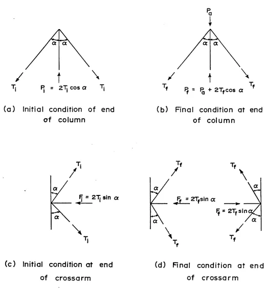
In a pretensioned single-crossarm stayed column, the initial
axial force (P.) is caused by the initial axial pretension (T^) in
the stays. The relationship between these forces is,
P. = 2T.cosa 3 , 1
i i
where a = the angle between the stays and the core.
The total final axial force (Pf) is defined as the force
including the applied force (P ) and the final tension component
cl
(Tf) . Thus, Pf is given by
... 3.2 p_ = p + 2T _cosa
f a f
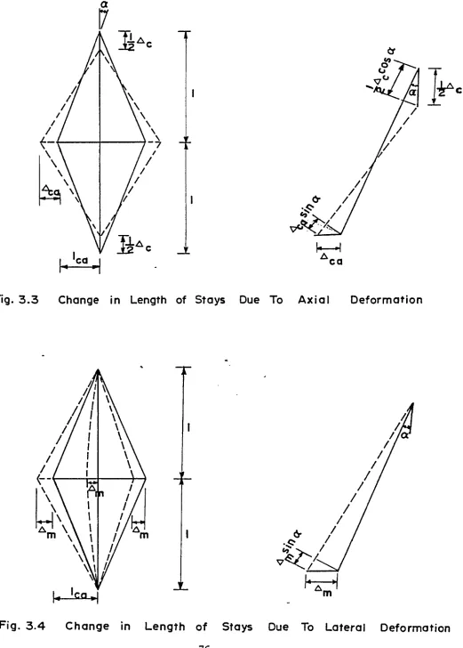
Due to the initial pretension, the core is shortened by an
amount (AL^), which is given b y
2 T .Lcosa 2T.cosa _ _
a. _ _i ...
A L i = A E K
C C C
where K = ■-c- - , the axial stiffness of the core;
c L
i rh-p fhe core; E = the modulus of
A = the cross-sectional area ot tne coie, c
elasticity o f the core; and L = the length o f the core.
There is also a horizontal component due to the initial pretension
which causes a compression force (F±) on the ends of crossarm which
results in a shortening of A2.c a ’
3.4 F. = 2T.sina
i i
2T.1 sina 2T.sina _
i ca _ a-... ....
A1 = — -— --- = — 77
ca A E K
ca ca ca
where K = c a ..,?.a. , the axial stiffness of the crossarm;
ca 1
ca
A = the cross-sectional area of the crossarm, E c = the modulus
ca
of elasticity of the crossarm; and lca = the length of the crossarm.
When a certain axial force is applied, the tension in the stays
will change to Tf , causing a compression force on the ends of the
crossarm equal to F^.
3.6 F = 2T_sinct
f f
Due to the applied force the column will be shortened by AQ ,
which is given by
13
B y substituting the values o f P f and P ± from Equations 3.1 and
3.2 into Equation 3.7, A c can be rewritten as
P - 2(T. - T )cosa
.______ a_____ i____ f_ 3.a
K c
Due to the decrease in the compression force, the c r o s s a r m is
elongated b y an amount equal to ^ c a > given b y
_ 2 ( F i ~ F f^ 1 ca _ F i ~ F f .... 3 . 9
ca A E K
ca c a ca
A n d A can also be w r itten in terms of the tension m stays,
ca
which is
2<T. - Tf )sina .... 3 .10
c a K
---ca
The stay is shortened due to the change in the stay tension and
the a mount o f shortening A^ is given as
(Tj _ t^)1_ Tj - T,_
3.11
s A E K ... ....
s s s
A E
where k = — --- , the axial stiffness o f the stay; A = the
cross-S Xs 3
sectional area of the stay; E = the modulus o f elasticity o f the s
stay; and 1^ = the length of the stay.
Due to the axial deformation o f the core and crossarm, A s
can also be written in terms o f the deformations,
A = -qA cosa - A sina 3.12
s 2 c ca
B y substituting the values o f A , A and A from Equations 3.8,
3.10 and 3.11 into Equation 3.12, the relationship between T ± , T f
and P is obtained a s , a
T - T [P - 2(T. - T_) cosa] cosa
i f _ a______ 3-____ £___________
K “ 23C
s c
[2 (T. - T _) sina] sina
1 « • • • « J • i.
K ca
The change in tension (Tj_ - T f ) can then be expressed in terms
o f the applied force, which is
m_____________ ________ cosa ... 3.14
T. - T = P 2 2
1 £ a 1 • 2sin a 2cos a.
2K c ‘~ + ~ K ~ ’
c s c a C
o r
T, - T. = P C, 3.15
i f a 1
where = — --- i— --- = a constant.
2K (L- + 2sin a + 2cos_a.
c K K K
s ca c
According to this equation, w h e n the tension in the stays
disappears, the applied load is the critical load, which is
T. - T T. - 0 T.
P = — ^---- - = — ---- = — 3.16
C 1 C 1 C 1
The maximum critical load (P ) is calculated by using the
c r ,max
^ n ite element method. The maximum critical load occurs only if
■the stays have an initial pretension equal to the o p t i m u m pretension.
Thus, the o p timum pretension can be predicted by
T . = c,P = optimum pretension 3.17
opt 1 cr,max
15
3.3 Real Stayed Column
3.3.1 Assumptions for a Real Stayed Column
The stayed column which contains an initial out-of-straightness
is called a real column. Before the analytical work was carried out,
several assumptions had to be made. These assumptions are not the
same as those for an ideal stayed column. The assumptions are:
(1) Due to the presence of imperfections, the single-crossarm
stayed column may not be symmetrical about both axes.
(2) The connections between the crossarm members and the core
are perfectly rigid. The connections between the stays and the
crossarm members, the stays and the core, are assumed to be ideal
h i n g e s .
(3) The deformations of all members are taken into consideration
when the buckling load and the tension in the stays is determined by
geometric analysis and the finite element method.
(4) The angle (a) between the stay and the core is considered
to remain unchanged.
(5) in some cases only two stays are effective when buckling
occurs, while in some other cases all stays are effective.
(6) All buckling loads of stayed columns with initial pretension
in stays are predicted by the finite element method using a nonlinear
ajialytical approach.
3.3.2 Definitions of Pretension Applicable to a Real Stayed Column
The terms which were defined for the ideal stayed column will
also be used for the real stayed column, b u t some are defined in a
(1) Minimum Effective Pretension: It is defined the same as
for the ideal stayed column. For the real stayed column, the
m i nimum effective pretension is slightly greater than the one for
the ideal stayed column. If the initial pretension is less than or
equal to the minimum effective pretension, the Euler load is the
failure load of the column.
(2) Optimum Pretension: The b u c kling load o f the stayed column
will be the maximum if the initial pretension is the optimum
pretension in the stays.
(3) Maximum Possible Pretension: It is the initial pretension
in the stays which gives a large vertical component at the ends of
the column. This component will cause a very large lateral deformation
without any additional load. The stayed column cannot resist any
applied load when the stays are stressed to the maximum possible
pretension.
(4) Residual Tension: When a real stayed column buckles a
certain tension will be left in the stays which is called the
residual tension. For a real single-crossarm stayed column, which
has an initial pretension between the minimum effective and optimum
pretension, there are residual tensions left in two stays at buckling.
When it has the initial pretension greater than the optimum pretension,
a ll stays will have residual tension at the buckling o f the stayed
column. W h e n it has the initial pretension less than the minimum
effective pretension, there will be no residual tension left in the
stay at the buckling load.
(5) Buckling Load: The buckling load is the actual buckling
17
strength o f the real stayed column. W i t h various pretensions and
stayed column parameters, the b u c k l i n g load will vary. In the
analytical study the b u c k l i n g load is obtained according to the
following definitions. These definitions are:
(a) W h e n the tension in the stays on the concave side of the
column reaches zero, the stiffness of these stays will vanish and
the column will then collapse. The applied axial load is considered
to be the buckl i n g load. This definition is similar to the one for
an ideal stayed column in which the column is considered to have
buckled* when all the tensions in the stays are zero.
(b) Under a certain axial .load the stayed column can also be
considered to have failed w h e n the lateral deflection or the
rotational deflection is large.
3.3.3 Geometrical Analysis for a Real Stayed Column
A two-dimensional single-crossarm real stayed column with p inned
ends is analyzed b y determining the relationship between the applied
load, stay tension and deflections.
W h e n the real stayed column is subjected to a certain applied
axial load, two types of deformation take place. These are the axial
deformation and the lateral deformation.
(1) Axial Deformation: The real stayed column behaves in the
same manner as an ideal stayed column under a compression axial load.
The core will be compressed, the stays will be shortened and the
crossarm will be elongated. Due to the axial deformation, as shown in
Figure 3.3, the shortening of the stays (A ), can b e expressed in s
crossarm (A ), w h i c h is C3.
A = crA cosa - A sina 3.12
s 2 c ca
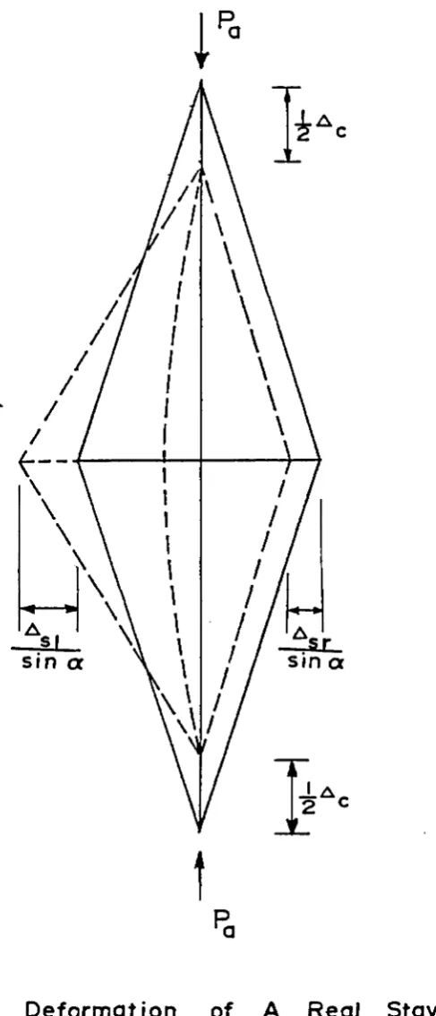
(2) Lateral Deformation: Due to the presence of imperfections
in the column, the lateral deformation is the m o s t important m a t t e r
to be considered. The lateral deflection w i l l cause different tension
in the stays. Assume that the s tayed column is deflec t i n g to the
left, as shown in Figure 3.4 and Figure 3.5. The a mount of lateral
deflection a t the c r o s s a r m level is A . It is a s sumed that the
m
displa c e m e n t a t b o t h ends o f c r o s s a r m are the same. T h e n the total
shortening of the stay is o b t a i n e d b y combining the results of axial
deformation and lateral deformation together. The total shortening
o f the stay on the convex side (left) o f the column is
A , = A - A sina
si s m
= -^A cosa - A sina - A sina 3.18
2 c ca m
A n d the total shortening of the stay o n the concave side (right)
of the column is
A = A + A sina
sr s m
= 77A cosa - A sina + A sina 3.19
2 c ca m
The a mount o f stay s hortening can also b e expressed b y the
change in stay tension, w hich is
T - T
Asi - -t ;— — 3 -2 °
S
T . - T _
A = --- — 3.21
sr K
s
19
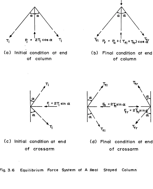
w h e r e = the final stay tension o n the left side of the column;
and T = the final stay tension o n the right side of the column. The
force s ystem of the real stayed column is shown in Figure 3.6.
The values o f A , A , A and A from Equations 3.8, 3.10,
C Gel S«1b S3T
3.20 a n d 3.21 are substituted into Equations 3.18 and 3.19 obtaining,
T + T
T i - T fl 1 . P a ‘ 2 ( T i ---2 £ c o s “ > .
--- J
t
^---J
cosa[2 (Ti - T^^) s i n a ] sina
K ca
- A sina
m 3.22
T . - T . P 2 (T.
-i fr _ 1_ r _ a ______ i
K 2 K
fl 'fr
cosa)
] cosa
2(T. - T^ )sinasina
i fr
K ca
+ A sina
m 3.23
B y a dding Equations 3.22 a n d 3.23 together,
T + T
2 T . - (T + T ) [P - 2(T. - --fl ^ c o s a ) ]
X XX X X cl X a
K K cosa
T + T
fl fr. . 2
4CT^--- }sin a
K ca
3.24
from w h i c h
IC 2 2
.. c , , 1 cos a , 2sin a,
P » --- [ 2T. - (T + T ) ] (— + — ---- + — ---- )
a cos i fl fr K K K
s c ca
3.25
E q u ation 3.25 gives the relationship of P^, T ^ , T ^ and T^r for
a single-crossarm stayed column for the first mode o f deflection.
tension can be expressed in terms of P and T . , which is
a i
Tf i + Tf r = 2Ti - - —
;—
- ^ — 2—
~ — T3-2S
K 1 cos a 2sxn a
— £_(— + + --- )
cosa K K K
s c ca
Subtracting Equation 3.2 3 from Equation 3.22, the following
equation is obtained
(T - - T_ ) . 2
A = (— + — — a ) 3.27
m 2sina K K
s ca
where the column mid-height deflection (A ) can be expressed by the m
final tension as in Equation 3.27.
3.4 Geometrical Nonlinear Analysis
3.4.1 General
Generally, two types of nonlinearity are found in structural
p r o b l e m s . These a r e :
(1) Nonlinearity through material properties, and
(2) Nonlinearity through large deformation and geometrical
changes in the structure.
In this study the nonlinearity due to the material properties
is neglected. Since initial out-of-straightness is always present in
real structural members, large deformation and geometrical changes in
the structure is an important matter to be considered for the
stability problem.
In the linear theory, the relationship between the applied
force {p} and the displacement {U} is given by
{P> = [K]{U> 3.28
where [K] is the linear elastic stiffness matrix for the structure.
21
In nonlinear theory, w h e r e displacements are large, Equation 3.28
is no longer valid since (1) the strain-displacement relations of
members are nonlinear, and (2) the equation o f joint e quilibrium
needs to b e w r i t t e n in terms o f the displaced geometry of the
s t r u c t u r e .
W h e n considering the s t r a in-displacement relationship higher
order terms n e e d to be included. In the analysis of a two-dimensional
structure the strain-displacement equation is
d u . l,dv\ 2 d2v ____________________________________________
Exx ■ — + 2 (— 1 " Y7 " 2 3 - 2 9
dx d x dx
where e =* the strain in the x direction; u = the local displacement
XX
in the x direction; and v = the local d i splacement in the y direction.
Since the finite e l e m e n t m e t h o d is u s e d for solving the
stability problem, the structure is divided into a number of elements
or substructures. The elements are interconnected at a discrete
number o f nodal points. The general displacement functions are chosen
for the elements. The total strain energy o f the structure is
derived and the minimization o f the strain energy w i l l provide the
final relationship b e t w e e n the load {p} and the displacement {u},
w h i c h is
[K_ + K ]{U} = {p} 3.30
where [K 1 = the m aster elastic stiffness matrix; a n d [K ] = the
£ G
master geometric stiffness matrix. The details o f the derivation
o f E q u ation 3.30 for a p l a n a r structure is shown in A p p endix A and
References 7 a n d 9.
geometry, b u t also on the initial internal load (P^) and hence, is
also called the initial stress stiffness matrix. This m a t r i x is
linearly proportional to the internal force a t the start o f the
loading step, and is given as
3. 31
w h e r e [K*] = the geometrical stiffness m a t r i x for a unit of internal
force (P^. = 1) . E q u a t i o n 3.30 can be rewritten in the form
tKE + P !Kg1{u} = {P} 3.32
E q u a t i o n 3.32 w i l l a c c o u n t for the nonlinear b e h a v i o r due to
large deformations o f the structure. This e q u ation does not, however,
include the influence of the e q u i l i b r i u m o f geometry and equili b r i u m
of forces. In o r d e r to include such effects in the analytical process,
consideration must be given to the m e t h o d of solving such nonlinear
equations. These methods w i l l be discussed in the following sections.
3.4.2 General Techniques for S o l v i n g N o n l i n e a r Equations
The solution o f the nonlinear p r o b l e m b y the finite element m ethod is
usually attempted b y three b a s i c techniques. These are:
(1) Iterative procedure.
(2) Incremental procedure.
(3) Mixed procedure.
In this section several techniques will be discussed w h i c h are
commonly used in solving nonlinear problems. F o r simplification, the
nonlinear E q u a t i o n 3.32 is p u t into a simpler form, w h i c h is
[k t H u> = {P} 3.33
where [K ] = a nonlinear stiffness m a t r i x and is a function of {u}
23
and {p}.
3.4.2.a. Iterative Procedure
The iterative p r o c edure is a sequence of repeated calculations
in w h i c h the structure is loaded for each iteration- Several values
are adjusted after each iteration until the result converges to a
steady value. Many different iterative approaches h a v e been
suggested for analyzing the n o n l i n e a r equation. Some of the common
procedures a r e :
(1) T a ngent Stiffness M e t h o d ^ ' ^
(Newton-Raphson Method) ,
(2) Secant Stiffness M e t h o d ^
(3) M o d i f i e d Tangent Stiffness M e t h o d ^ ' ^ '
(4) M o d ified S e c a n t Stiffness M e t h o d ^ ' ^ ^ ,
20
(5) T a n g e nt-Secant Stiffness M e t h o d , and
23
(6) Successive Substitution M ethod
The methods of tangent stiffness and secant stiffness w i l l be
discussed in this section. These methods show the b a s i c ideas of
how the iterative procedure works.
(i) T a ngent Stiffness Method: This m e t h o d is similar to the
Newton-Raphson technique.. The final solution is obtained as the
sum o f the successive estimates that are calculated d uring each
cycle o f iteration. The technique is illustrated b y a schematic
diagram in Figure 3.7. The iterative scheme is
= [K T a n 1]{Aul} L = 1 '2 '3 '---1 . 3 * 3 4
i s
{UT > = I{AU } ... 3.35
where {p_1 - 1 } = the remaining unbalanced load vector at the i"*"*1 cycle