Available Online atwww.ijcsmc.com
International Journal of Computer Science and Mobile Computing
A Monthly Journal of Computer Science and Information Technology
ISSN 2320–088X
IMPACT FACTOR: 6.017IJCSMC, Vol. 8, Issue. 3, March 2019, pg.249 – 256
Design of Communication System
for Smart Factory Controlled by
PLC based on IOT Technology
Hussein Tiarah Abd Ali Gharbawee
Electrical and Computer Engineering, ALTINBAŞ UNIVERSITY, Istanbul- Turkey
Raad Farhood Chisab
Dept. of Electrical Techniques- Technical Institute-Kut, Middle Technical University (MTU) Baghdad-Iraq
Oguz Bayat
Electrical and Computer Engineering, ALTINBAŞ UNIVERSITY, Istanbul- Turkey
Abstract— A smart factory is an extremely digitalized and associated fabrication capability that depend on smart industrialized. the model of the smart factory is considered as new idea for the 4th manufacturing revolution. The major features for smart factory are perceptibility, communication and independence. Industrial unit have extended trusted on robotics. The GLOVA G7-DR20U is used as a programmable logic controller PLC for control the action of smart factory while using the NodeMcu esp8266 as the IOT board for communication between owner and the factory using the smart phone programming. The software programming in the mobile phone was written in MQTT program. The program which written inside PLC by using ladder language for controlling the work of PLC. The prototype of smart factory was containing from two motor one for horizontal movement while the other for vertical movement. The scheme moreover has six sensors. Every motor attach with double sensors to bound its movement. The other two sensors are one for detect the exist of production while the other for count the production in the output side. When running the system, it is shown that the system is working very well and the response to the communication system via IOT is very good also receiving and sending the information to the mobile phone without errors.
Keywords— PLC, smart factory, IOT, NodeMcu
I. INTRODUCTION
crosswise total industrial source restraints, comprehensive creation life-cycles, numerous productions, with minor, middle and great creativities. that notion was characterized via a “Smart Factory or notation by SF” that trusts on inter-operable structures. This is multiscale active forming with imitation; smart computerization; climbable, multi-level replicated safety; and interacted devices [1]. that initiatives employ facts and data through the whole creation lifetime round through the aim of making elastic industrial procedures that reply quickly to alterations in request at little rate for stable, in addition to the situation. that procedures enable the movement of info crossways entirely commercial roles private the initiative and accomplish the networks to providers, clienteles, also extra investors external the initiative..
II. SMART FACTORY
Smart factory is a comprehensive group of developed for aiming of enhancing idea cohort, manufacture, and produce contract. The shape of smart factory can be shown in figure 1. Though industrial could definite as poly-phase procedure for generating invention beyond basic resources, clever industrial is a subset that employments processer governor and great stages of adaptableness. Clever industrial goals to revenue benefit of progressive info and developed skills to permit elasticity in corporal procedures to report a active and international fair. it is improved personnel preparation to like plasticity and usage for skill somewhat than exact responsibilities same usual for outdated developed [2]. This idea is demonstrated in figure 1. Progressive automata, likewise identified as clever machineries work separately and could join straight with industrial schemes. for approximately progressive industrial frameworks, it could effort through persons aimed at meeting responsibilities. Through estimating corporeal effort and unique among diverse creation formations, that machineries were capable to resolve difficulties and mark choices self-governing of persons. that automata were capable to comprehensive effort yonder that primarily automatic to did and has simulated cleverness that permits them to study after involvement [3]. that machineries take the elasticity to be re-configured. This contributes them the capability to reply quickly to enterprise alterations and invention, that is a modest benefit above extra outdated industrial procedures.
Figure 1: motorized manufacture as smart factory.
III. INTERNET OF THINGS (IOT)
The meaning of the IOT has grown because of merging of numerous tools, actual time analytic, mechanism education, product instruments, and surrounded schemes. Outdated grounds of entrenched schemes, robotics (containing homebased and construction robotics). also entirely donate for allowing the IOT.
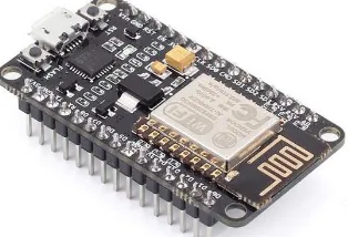
The idea of a system for clever plans is deliberated as initial in 1982. this a adapted Coke instrument at “Carnegie Mellon University”. This is a primary Internet linked application, capable to account its record and if anew encumbered drink was icy. The IoT is the net of plans, automobiles and homebased applications which comprise microchip technology, software, sensor, and connective that permits these effects toward attach, interrelate and conversation information. In figure 2 the NodeMcu was used as the IOT technology
The internet of things includes covering net. connection outside typical strategies. This is similar to desk-tops, lap-tops and smart-phones. for somewhat kind of conventionally dumbing or never-internet-enable corporeal equipment with every-day items. Implanted with knowledge, these strategies can interconnect and interrelate ended the Internet, . it could distantly have observed and organized [4].
IV. THE PROGRAMMING LOGIC CONTROLLER (PLC)
Within 1968 General Motors Hydromantic delivered an appeal for suggestions to electric spare to solid bound relay schemes. This is grounded for a manuscript printed by Eng. E. R. Clark. charming suggestion derived as of Bedford Connections from Bedford, Massachusetts. The primary programmable logic controller, selected the 084 since they are Bedford Companions' 84 mission, is the product. Bedford Acquaintances ongoing a original corporation devoted to emerging, industrial, vending, and repairing that novel invention: “Modicon”. That product erected to segmental numerical control. Some persons that operated within mission is “Dick Morley”. This person was regard as the "father" for programmable logic controller [5]. The shape of PLC can be shown in figure 3.
Contemporary PLC could program within a diversity of methods, beginning with relay derived hierarchy logic reach to other language like especially modified for “BASIC and C”. Additional technique was national logic. This is an exact great level software design language considered for software package PLC rely on state changeover figures. The widely held for PLC schemes nowadays follow of “IEC 61131/3” governor schemes software design normal which describes five-languages: “Ladder Diagram (LD), Structured Text (ST), Function Block Diagram (FBD), Instruction List (IL) and sequential function chart (SFC)”.
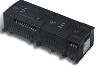
Figure 3: the GLOFA GM7U PLC
Several primary PLC never contain supplementary software design stations which accomplished graphic demonstration for sense. also sense in its place characterized like a sequence for sense terminologies within around form of Boolean arrangement. This is alike to Boolean algebraic. the prime aim to that was the PLC resolve sense within a foreseeable and reiterating order. also ladder sequence permits the computer operator for understand some matters within skill for logic arrangement extra simply more than further format [6].
PLC programming is classically inscribed in a superior presentation in a private PC. the transferred by a direct connect tow and above net through programmable logic controller. The program-sequence was storing inside programmable logic controller. this is done in two method the first one was within battery-RAM or extra never volatile flash memorial.
Additional lately, PLC were programming by means of request software in private PCs. it represents logic within explicit shape in its place for characters’ symbol. a PC was linked via programmable logic controller over USB, Ether-net and other methods connections. a program of soft-ware permits entrance with excision for ladder system sense. also can likely to sight with editing a programming in meaning block-diagrams, flow-charts or structured-text. Usually, a soft-ware delivers roles for repairing and trouble-shooting the programmable logic controller soft-ware. for instance, for importance parts for logic in showing present state through process and by simulations. a software then uploads or transfer a programmable logic controller driver, aimed at back-up and rebuilding devotions. within other simulations in programming governor, the programs are transfer beginning from a PC to programmable logic controller over a programmed board that inscribes a driver to a transferrable chip like EPROM [7].
V. THE PROPOSED SMART FACTORY
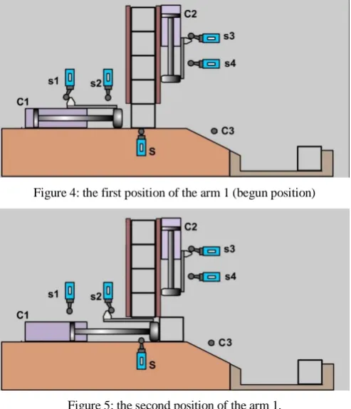
over the box of product in the right position. In the first the switch s1 is ON while switch s2 is Off position. That position means the arm, which is work for pushing the box to right position, was in first position or named starting position in order to be ready for next position. The switch s3 stay in ON position and s4 stay in OFF position. The sensor C3 (which is the count sensor) is the counter the calculate the amount of the product and send the final number to the owner in order to has a full monitor and control on the factory. Now begun with the next step which depend on the position of arm 1. In this position the arm will be moved to left. The switch s1 return to OFF position and s2 also stay on the OFF position. The arm continues to move until the switch s2 turn its state to ON position. In this case the arm will suddenly stop and in this case the box of product will in position outside the queue of product and be ready. The sensor s3 will stay in ON position and s4 stay in OFF position. In this case the switch S return to OFF position that means the box is moved to new position and ready to receive the new box product. Now in the third position the arm1 begun to return to first position to let the arm 2 to begun move to new position. In this third position the arm begun to move to left side and the micro switch s2 return to OFF position until the switch s1 return to ON position. The sensor S return to ON position that indicate the new box production was existing in the right position and ready to pushed under the arm 2.
Figure 4: the first position of the arm 1 (begun position)
Figure 5: the second position of the arm 1.
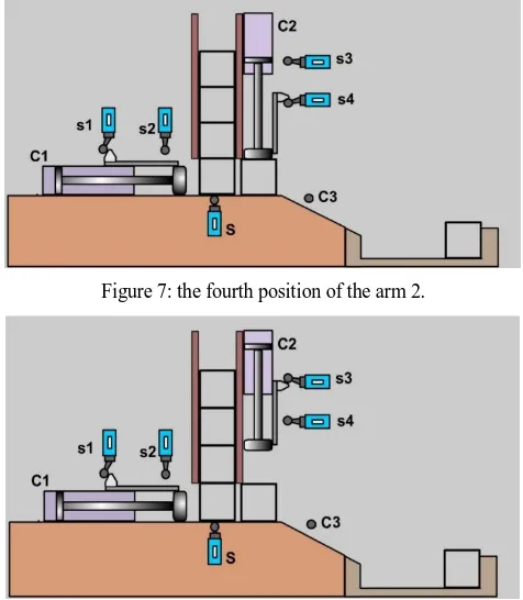
The fourth position was shown in figure 7. in this figure it can be noticed that the arm 1 was stay in the same position and never moved that means the s1 stay ON state and s2 stay on OFF state. The arm 2 change its state and move from up to down that means the sensor s3 changed his state from ON state to OFF state and the arm continue move until reach the right position then the sensor s4 changed its state from OFF state to ON state. At this moment the arm will stopped and press the box of product and put the trademark or expiry date of production box.
Figure 6: the third position of the arm1.
mark on the boxes for production. After these cycle the box will be slide down and pass through the sensor C3 and this lead to increase the amount of counter by one and send this information to the owner.
Figure 7: the fourth position of the arm 2.
Figure 8: the final position of the machine for arm1 and arm 2.
VI. THE CONNECTION OF PLC WITH SMART FACTORY
The connection of the programmable logic controller (PLC) with the smart factory was shown in figure 9. in this figure it can be noticed the symbols S, S1, S2, S3, S4, start and stop switches. These switches are governing the work of the smart factory. It can be shown that these switches are connected to input side and the inputs to these switches are the positive side of the DC power supply while the other side of the switches are connected to the input side of the PLC at the point numbers I00, I01, I02, I03, I04, I05 and I06 respectively. The PLC needed two types of inputs which are D.C. And A.C. the AC was entering to PLC via N and R. also it can be noticed that the PLC was connected to the internet of thinks using the NodeMcu board by controlling the start switch of the PLC. That means the starting of the PLC working was controlled by two methods which are manually by pressing stat bottom and the other method using the internet of thing via the NodeMcu board. Also the IR sensor was connect to NodeMcu that is used to calculate the number of production boxes when the factory was running.
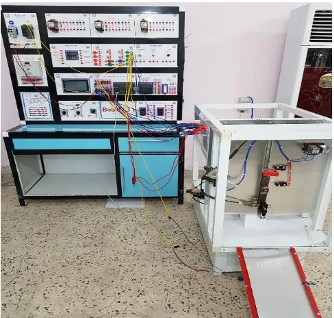
The figure 10 demonstrate the real connection of the PLC with the prototype of smart factory that is containing the two motors with sensors for position detection and for counting the product
VII.THELADDERPROGRAMMING
In this part the discussion of the ladder program is done. all the variable which used in the simulation are demonstrated. Below the variable were define in the program and can see how the dealing with that variable are effect on the run the program
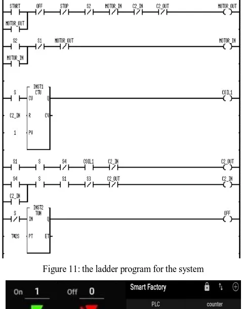
The shape of ladder language or the diagram that explain the program (simulation) that govern the process of smart factory that is connected to internet was shown in figure 11. The ladder language which can be drawn in figure 11 is divided to six lines and each one is used for special purpose and do the specific job in the smart factory. The first line was used to control the working of the horizontal motor which is used to push the box to right side in order to prepare the box to be exactly lower the vertical motor. This line is regarded the core of the process overall because it is the first step to begin the work of PLC. It depends on different factor or switches that must be closed to connect the line of electricity to the horizontal motor like START bottom must be open then changed to close and OFF must be closed and so on as shown in figure 11. The second line which is used to return the the horizontal motor to normal place and move it to left side and this is also depend on some parameter of switches like S2, S1, and so on. The third line was used as counter and auxiliary for preparing to the vertical motor and contain the present value and current value and compare between them and other parameter that assist the vertical motor to do its job. The fourth line is used to move the vertical motor to down side. This line contains five parameters that controls the activity of the motor such as S1, S, S4 and so on. When all this parameter is closed then motor is down until reach the specific point and the switch S4 is touch and become open then the vertical motor is stop. The fifth line is used to up the vertical motor to the first or up position and this line depends on six parameters which are S4, S, S1 and so on as shown in figure 11. When the motor begun to up position it continue up until the arm of the motor touch the switch S3 then it became open and the motor stop. The last line or sixth line was used to turn off the PLC and end the process and this line depends on the switch S which is related to the boxes in the production line. When the boxes is finish then the switch S become OFF or open then this line is open and the PLC will be turn off
Figure 10: the practical connection of smart factory using PLC and NodeMcu
VIII.CODES FOR NODEMCU
Figure 11: the ladder program for the system
Figure 12: the program for mobile phone for control
IX. CONCLUSION
Previously, the idea of smart factory was regard as the dream of manufacturers and owner of factories because the management of the factory is never easy thing. Also the amount of error that may be occurs during the hours of works is very high. Now, and exactly when the principle of smart factory is spread and become more common the management of the factory become more easily and the number of workers that exist in the smart factory is near to zero persons. Therefore, the smart factory reduces the effort that the owner gives and reduce the problems that may be occurs during the work and also reduce the risks that may the workers face it. The major benefit from smart factory was that this era of factories reduces the money spending as salary for workers specially if we imagine that the amount of workers that this factory will reduced. This lead to major and great benefit to the owner of factory which is the cost of product. This means that the principle of champion between the different product is very high and the customers will get a good chance to take high quality with lower price products. In this thesis an additional benefit was added to the principle of smart factory which is the internet of things. This means that the owner can manage his factory remotely without need to come and see his factory and also the owner can know everything about the amount of product that the factory produces and also if the factory faces some problem. Therefore, this facility gives the owner the possibility of turn off his factory before crises occurs. Therefore, these additional facilities added more benefit for the owner which is he safe the waste time for monitoring and reduce the cost of product because no need for persons that must exist in factory for monitoring the product and can monitor the factory from any position in the world. Finally, the owner has the major benefit over reduce the effort and money that he makes his factory safer and the thief cannot try to take anything from factory if we added some sensor for movement to detect thief and can call police without coming to factory.
R
EFERENCES
[1] Mattern, Friedemann; Floerkemeier, Christian (2010). "From the Internet of Computer to the Internet of Things" (PDF). Informa tik-Spektrum. 33 (2): 107–121. Bibcode:2009InfSp..32..496H. doi:10.1007/s00287-010-0417-7. Retrieved 3 February 2014.
[2] Kang, Won Min; Moon, Seo Yeon; Park, Jong Hyuk (5 March 2017). "An enhanced security framework for home appliances in smart h ome". Human-centric Computing and Information Sciences. 7 (6). doi:10.1186/s13673-017-0087-4
[4] Lopez, Javier; Rios, Ruben; Bao, Feng; Wang, Guilin (2017). "Evolving privacy: From sensors to the Internet of Things". Future Generation Computer Systems. 75: 46–57. doi:10.1016/j.future.2017.04.045
[5] Harms, Toni M. & Kinner, Russell H. P.E., Enhancing PLC Performance with Vision Systems. 18th Annual ESD/HMI International Pr ogrammable Controllers Conference Proceedings, 1989, p. 387-399.
[6] Maher, Michael J. Real-Time Control and Communications. 18th Annual ESD/SMI International Programmable Controllers Conference Proceedings, 1989, p. 431-436.