Vol. 5, Issue 6, June 2016
Comparative Characteristic Analysis and
Study of Several QCA Inverters
Waseem H. Wani1, Z. A. Bangi2, S. Umira R. Qadri3, M. Tariq Banday4, Dr. Saroj Patel5
PhD Scholar, Department of Computer Application, Jodhpur National University, Jodhpur–Rajasthan, India1
M.Phil Scholar, Department of Electronics and Instrumentation Technology, University of Kashmir, Srinagar, India2
PhD Scholar, Department of Electronics and Instrumentation Technology, University of Kashmir, Srinagar, India3
Sr. Asst. Professor & Coordinator, Department of Electronics and Instrumentation Technology, University of Kashmir,
Srinagar, India4
Associate Professor, Department of Mathematics, Jodhpur National University, Jodhpur–Rajasthan, India5
ABSTRACT:Quantum-dot Cellular Automata (QCA) is a new knowledge for growth of logic circuits based on nanotechnology and is one of the choices for designing high performance logic structures over existing CMOS technology. The basic logic in QCA does not utilize voltage level for logic representation,though it represents binary state by polarization of electrons in the Quantum Cell. Fundamental elements of QCA are the Inverter and the Majority voter.This paper presents the fundamentals of QCA technology andvarious inverter designs that are available in literature with their simulation results in QCA. Further, a comparison made on all previously reported inverter designs in accordance with cell count, polarization, occupied area and fault tolerance has been presented. In addition,conclusion has been drawnon the basis ofinverter comparison.
KEYWORDS: Nanotechnology, Nano-electronics, Quantum-dot Cellular Automata,Inverter, Circuit Simulation, Arithmetic Computing.
I. INTRODUCTION
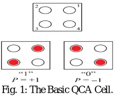
QCA is a novel nanotechnology that attempts to constructbroad computation at the Nano scale by organizing the position of single electrons. The basic building block of QCA is presented in Fig. 1.
Fig. 1: The Basic QCA Cell.
QCA cell consists of four quantum dots in a four-sided array tied by tunnel barriers. Columbic interaction is the physical means of communication between the quantum dots and the quantum-mechanical tunnelling. Electrons are able to tunnel between the dots, but they cannot run off the cell. When two mobile electrons are placed in the ground state[1] of the celland in the absence of external electrostatic manipulation, Columbic repulsion will force the electronsto move to the opposite corners [4] of the cell. The two possible charge configurations or the polarizationstates of the cell has been presented in Fig. 1 corresponding to binary ‘1’(+1) and ‘0’(-1). For an isolated cell, the two polarization states are energetically equivalent.If the four dots are tagged from 1 to 4 anti-clockwise starting from the
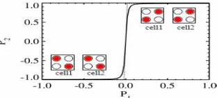
P =( ) ( ) (i) The polarization of a non-isolated cell is obtained based on the interaction between the neighbouring cells [5][6].The cell-to-cell response function for two neighbouring cellsis shown in Fig. 2, where cell 1 is the driver cell whose polarization P1 takes the range from −1 to 1 andthe polarization of cell 2 changes for other values of the driver cell. It is observed that if the polarization of the driver cell 1 will changerepeatedly from −1 to 1, then the polarization of cell 2 will varyquickly from −1 to 1which in turn increases the robustness of cell 2’s state because even if cell 1 is far away from saturation polarization value, cell 2 will still be near to −1 or 1.
Fig. 2: Cell to Cell Response Function for Two Neighbouring QCA Cells.
In QCA, cell will toggle from one polarization to the other when the electrons automatically tunnel from one pair of dots to theother pair. The rectangle box shown around cells is used to recognize one cell from the other; they do not symbolize any physical system. In point of fact, electrons are quantum particles, which are able to tunnel between the dots in a cell;electrons in cells which are positionedneighbouring to each other will interact. Thus, the polarization of one cell will be directly affected by the polarization of its neighbouring cells. This interaction forces neighbouring cells to synchronize their polarization as shown in Fig. 3. Therefore, an array of QCA cells act as a wire and is able to pass information from one cell to other, i.e. all the cells in the wire will toggle their polarizations to follow the input or the driver cell. In this technique, information givento the input is reflected at the output after a short propagation delay shown in Fig. 3.
Fig 3: Neighbouring Cells Tend to Align due to Columbic Coupling
II. QCA INVERTERS
Since the two essential logic elements of QCA technology arethe Majority voter and Inverter.An inverter cannot be made with the help of a majority voter,thus it has to be implemented or designed separately. Henceforth, inverters can be implemented with lines of diagonally aligned cell with opposite polarization. There are number of logics used to design the inverters. An example of a QCA inverter is shown in Fig. 4.
Fig. 4: Inverter, using the Interaction of Diagonally Aligned Cells to Invert Bits.
Vol. 5, Issue 6, June 2016
placing a standard cellin the middleof an even and odd rotated cellsbut that will lead to a blurred signal. The truth table of an inverter or NOT gate is shown in Table I.
Table I: Truth Table of Inverter
Input Output
0 1
1 0
There are a number of inverters available introduced by various researchers. Some of themare given below;
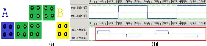
A. Lent et al Inverter Model
Lent et al introduced the QCA inverter, whichbasically inverts the signal by a cell displacement [2]. The advantages include less complexity,less estimated area and less polarization.Therefore fault tolerant capability is very lessand does not generate accurate results each time. The diagrammatic representation, simulation results areshown in Fig.5 and its characteristics in Table II.
(a) (b)
Fig. 5: QCA Implementation and Simulation Result of lent et al Inverter
Table II: Characteristics of Lent et al Inverter
Polarization Complexity Estimated area (nm2)
0.559 4 2964
B. Farazkish et al Inverter Model
Farazkish et al introduced the QCA inverter, which is very analogous to Lent’s Model. Based onsome physical and arithmetical calculationsit has been proved that this method is completely true [8]. This technique can be supportive in decreasing complicacy of QCA designs as it removes some cells in a QCA inverter or NOTgate, without disturbing the functionality ofan inverter. The diagrammatic representation, simulation results are shown in Fig. 6 and its characteristic in Table III.
(a) (b)
Fig. 6: QCA Implementation and Simulation Result of Farazkish et al Inverter
Table III: Characteristics of Farazkish et al inverter
Polarization Complexity Estimated area (nm2)
C. Tougaw et al Inverter Model
Tougaw et al introduced the QCA inverter where the signal is alienated into two paths. It amplifies the signal which results in better polarization at output. ThisQCA design is geometrically symmetric, so inversion from 1 to 0 or vice versa occurs with the same consistency [7]. The diameter of each dot is proportional to the charge on the corresponding site which is obtained from self-consistent solution for the ground state charge distribution. The diagrammatic representation, simulation results are shown in Fig. 7and its characteristic in Table IV.
(a) (b)
Fig. 7: QCA Implementation and Simulation Result of Tougaw et al Inverter
Table IV: Characteristics of Tougaw et al Inverter
Polarization Complexity Estimated Area (nm2)
0.775 8 5684
D. Navi et al Inverter Model
Navi et al Inverter is based on two layer and three layer modelling, yet all introduced models have been implemented in one layer i.e.singlelayer design. When two QCA cells on a straight line, affect each other, the signal propagatesrepeatedly. Though, when the two cells affect each other with a 45o angle, the signal could invert. This trend is the basis of all surveyed QCA inverters. This inverter model also usessimilar idea with aslight change i.e., the neighbouring cells are not located in the same layer and they invert the signals while propagated from one layer to another.
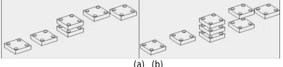
The diagrammatic representation and its simulation resultsare shown in Fig. 8 and its characteristics in Table V respectively. Even though polarization in both models proposed by Navi is better than the single layer design, each model has its own advantages and disadvantages according to the application. The second model has better polarization than the first one. However, the second model has been implemented in three layers instead of two layers [6].
(a) (b)
Fig. 8: (a) Two-Layer Inverter (b) Three-Layer Inverter.
Table V: Characteristics of Navi et al Inverters
Inverter Polarization Complexity Estimated Area (nm2)
Two layer 0.588 6 1764
Three layer 0.842 8 1764
E. Angshuman et al Inverter model
Vol. 5, Issue 6, June 2016
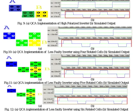
QCADesigner tool. The polarization from the simulation is ± 0.976, which is greater than any conventional three normal cell inverters.Since fault free inverter circuit has the polarization of ± 1.00, hence the inverter circuit shown in Fig.9 is having faults. Thus, it is understood that the increase in polarization makes the inverter fault free [9].
In order to minimize the faults in the inverter i.e. to increase the polarization of the inverter, one extra rotated cell is added with the output to make the inverter more fault free as shown in Fig. 9(a).The inverter circuit shown in Fig.10(a) has four rotated cells and corresponding simulated output is shown in Fig 10(b). It has been seen that the polarization becomes ± 0.994, which confirms that the inverter is nearly fault free. Inverter with an addition of two extra cells at the outputis shown in Fig 11(a). The polarization in the simulated output shown in Fig 11 (b) becomes ± 0.997. The inverter shown in Fig 11 (a) is more fault free than the above designed inverters. To boost the polarization i.e. to make the inverter circuit more faults free, three extra cells are added at the output of the faulty inverter shown in Fig 12 (a),but the polarization remains same as the polarization of inverter circuit shown in Fig 12 (a).Therefore, the final inverter circuit is shown in Fig 12 (a);and one can say that the inverters of Angshuman et al are almost fault free circuits.
(a) (b)
Fig. 9: (a) QCA Implementation of High Polarized Inverter (b) Simulated Output
(a) (b)
Fig.10: (a) QCA Implementation of Less Faulty Inverter using Four Rotated Cells (b) Simulated Output
(a) (b)
Fig.11: (a) QCA implementation of Less Faulty Inverter using Five Rotated Cells (b) Simulated Output
(a) (b)
Fig. 12: (a) QCA implementation of Less faulty Inverter using Six Rotated Cells (b) Simulated Output
Table VI: Characteristics of Angshuman et al Inverters
Inverter Polarization Complexity Estimated size (nm2)
High Polarised Inverter 0.976 3 2476
F. Khanday et al Inverter Model
Khanday et al designed two new inverters shown in Fig. 13 and its simulated results are shown in Fig. 14.The first proposed design, shown in Fig. 13(a), is composed of only three cells. The first input and the third output cells are oriented at 90 degrees and the second middle cell is oriented at 45 degrees. The combination of these three cells makes the Inverter [10]. Compared to the [10][9][8][3] inverters, this design is not only having lesser area but also highly polarized and efficient. The second proposed design shown in Figure 13(b) is composed of four cells. The Middle two cells are oriented at 45 degrees and the other two (input and output) cells are oriented at 90 degrees. This design is having high polarization and is robust enough as compared to the previously designed inverters [10][9][8][3].
The polarizations in these designs are better than the earlier models and have the benefit of superior performance in terms of noise, circuit stability and power consumption. It is better to make single layered QCA circuits instead of Multi-layered [3].The simulation results are shown in Figure 14(a) and Figure 14(b).
(a) (b)
Fig. 13: QCA Implementation of Khanday et al Inverter
(a) (b)
Fig. 14.Simulated Results of Khanday et al Inveters
Table VII: Characteristics of Khanday et al Inverters
Inverter Polarization Complexity Estimated Area (nm2)
3 cell based 0.879 3 1624
4 cell based 0.969 4 2204
G. AOI (And-Or-Inverter) Inverter Model
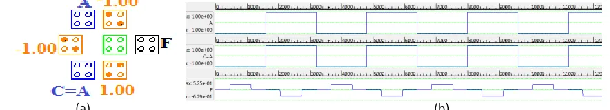
AOI gate is the universal gate consists of seven cells with five inputs, one device cell and one output cell. It can be built from the original 5-cell Majority Voter (MV) by adding two extra inputs (A and C). The advantage of these two inputs is having an inverting effect on the centre cell as one can see from the layout of the inverter cells in a diagonal orientation at 45°, whichreveals an inverting function [11]. The QCA Implementation of AOI inverter, its simulation results are shown in Fig. 15 and its characteristics in Table VIII.
(a) (b)
Vol. 5, Issue 6, June 2016
The major disadvantage of universal AOI gate is that the marginal cell misplacement may change its logic function immediately.
Table VIII: Characteristics of AOI Inverter
Polarization Complexity Estimated Area (nm2) +0.525 and -0.629 7 12744
H. NNI (NAND-NOR-INVERT) Inverter Model
NNI is also the universal gate which consists of five cells. Every cell in an NNI gateis attached to the same clocking region of QCA [12]. The vertical (horizontal) separation between inputs of an NNI gate is same and, consequently the NNI structure guaranteesconstancy in comprehending the adaptable logics. It does not contain device cell and proves more reliable as compared to the universal AOI gate. Two inputs (B and C) are set to +1 polarization (i.e. at logic 1). The QCA implementation of universal NNI gate based Inverter, its simulation results are shown in Fig. 16 and its characteristics in Table IX.
Fig. 16 : QCA Implementation of NNI Inverter and Simulation Output
Table IX: Characteristics of NNI Inverter
Polarization Complexity Estimated Area (nm2)
+0.948 to -0.951 5 4524.00
I. FNZ Inverter Model
The QCA implementation of the universal FNZ gate [8] based Inverter Model is shown in Fig. 17(a) and its simulation result is shown in Fig. 17(b). The design comprises of 8 cells with three inputs and one output. One of the input is vertically translated to 10nm while as the other two inputs are horizontally translated to 10nm making the whole design to occupy 6084nm2(0.01μm2). Two of its inputs are set to -1 polarization (i.e. at 0) to perform inverter logic [13]. The characteristic table of FNZ inverter model is shown in Table X.
(a) (b)
Table X: Characteristics of FNZ Inverter
Polarization Complexity Estimated Area (nm2)
0.931 8 6084.00
The universal FNZ gate will enjoy flamboyant advantages of cell count, less latency, fast response, smaller cell/overall area and less power consumption as compared to the ones designed by employing the AOI or NNI universal gates and proved to be much robust and advantageous.
The comparison tableand graph of all inverters is shown below;
S. No Model Complexity Polarization Estimated area(nm2)
1 Lent.al 4 0.559 2964
2 Farazkish 6 0.486 3724
3 Tougaw 8 0.775 5684
4 K.navi (2 layer Model) 6 0.588 1764
5 K.navi (3 layer Model) 8 0.842 1764
6 Khan’s High Polarized Model 3 0.976 2476
7 Khan’s Less faulty Inverter using 4 rotated cells 4 0.994 4464
8 Khan’s Less faulty Inverter using 5 rotated cells 5 0.994 5941
9 Khan’s Less faulty Inverter using 6 rotated cells 6 0.994 7434
10 Khanday et al (3 Cell) 3 0.879 1624
11 Khanday et al (4 Cell) 4 0.969 2204
12 AOI inverter 7 0.525 12744
13 NNI Inverter 5 0.948 4524
14 FNZ inverter 8 0.931 6048
Fig. 18: Comparison of QCA Inverters 4 6 8 6 8 3 4 5 6 3 4 7 5 8 0 .5 5 9 0 .4 8 6 0 .7 7 5 0 .5 8 8 0 .8 4 2 0 .9 7 6 0 .9 9 4 0 .9 9 4 0 .9 9 4 0 .8 7 9 0 .9 6 9 0 .5 2 5 0 .9 4 8 0 .9 3 1 2 .9 6
4 3.72
4 5 .6 8 4 1 .7 6 4 1 .7 6
4 2.47
6 4 .4 6 4 5 .9 4 1 7 .4 3 4 1 .6 2 4 2 .2 0 4 1 2 .7 4 4 4 .5 2 4 6 .0 4 8 0 2 4 6 8 10 12 [2 ] [8 ] [7 ] [6 ] [6 ] [5 ] [5 ] [5 ] [5 ] [10 ] [10 ] [11 ] [12 ] [13 ]
Vol. 5, Issue 6, June 2016
III. CONCLUSION
The QCA cell, its properties and a number of QCA Inverters has been discussed. QCA Inverters must have the less complexity and lessestimated area and lowpower dissipation. Therefore, an efficient QCA Inverter must have high polarization, less number of cells, thus less area and less delay. As algebra equations that created the outputs of circuits to be simpler, so that the circuit is competent in cell count, delay and other features. It has been observed that multilayer model of inverter shows better polarization (3-layer model) along with better area use butat the increased cost. Therefore, there is a tradeoff between delay cell count/area and robusting features. It becomes necessary that the designer have to choose the design based on above-mentioned requirement. Finally, it is emphasized that Khanday et al has less complexity, less delay and less power consumption and high polarization as compared to others. Therefore as per features studied of several Inverters, Khanday et al is the better model and having fault tolerant capabilityas compared to others.
REFERENCES
[1]. Lent, C. S., Tougaw P. D.,Porod, W.,Quantum, 1994. Cellular Automata: The Physics of Computing with Arrays of Quantum Dot Molecules,PhysComp ’94: Proceedings of the Workshop on Physics and Computing, IEEE Computer Society Press, pp. 5-13.
[2]. Lent, C. S., Quantum cellular automata,1993.Nanotechnology, Vol. 4, No. 1, pp. 49-57.
[3]. Tougaw, P. D., Lent, C. S., 1994. Logical Devices Implemented Using Quantum Cellular Automata, Journal of Applied Physics, Vol. 75, No. 3, pp. 1818-1825.
[4]. Meurer, B., Heitmann, D., Ploog, K., 1993. Excitation of three dimensional quantum dots, Physical Review B, Vol. 48, pp. 1488–1491. [5]. Amlani, A. O. Orlov, G. Toth, G. H. Bernstein, C. S. Lent and G.L. Snider, “Digital logic gate using quantum-dot cellular automata,” Science,
Vol. 284, pp-289–291, 1999.
[6]. Navi, K., Tehrani, M. A., Khatami, M.: Well-Polarized Quantum-dot Cellular Automata Inverters. International Journal of Computer Applications, 58, 10-13 (2012).
[7]. Tougaw, P.D., Lent C.S.: Logical devices implemented using quantum cellular automata. Journal of Applied Physics, 75, 1818-1825 (1993). [8]. Farazkish, R., Azghadi, M.R., Navi, K., Haghparast, M.: New Method for Decreasing The Number of Quantum Dot Cells in QCA Circuits.
World Applied Sciences Journal, 4, 793-802 (2008).
[9]. Angshuman Khan, RatnaChakrabarty Novel Design of High Polarized Inverter Using Minimum Number of Rotated Cells and Related Kink Energy Calculation in Quantum dot Cellular Automata.
[10]. Bangi, Z. A., Khanday F. A., Shah N. A: Design of Novel Quantum-dot CellularAutomata (QCA) Inverters J. of Active and Passive Electronic Devices, Vol. 9, pp. 271–279
[11]. Jing Huang, Mariam Momenzadeh, Mehdi B. Tahoori and Fabrizio Lombardi.: IEEE Transactions On Computer-Aided Design Of Integrated Circuits And Systems 24(12):1881 - 1893 · January 2006
[12]. Pijush Kanti Bhattacharjee, Digital Combinational Circuits Design By QCA Gates International Journal of Computer and Electrical Engineering, Vol. 2, No. 1, February, 2010