Multilevel Inverter Based STATCOM for
Load Balancing System in Power System
B.Prabakaran 1, A.Mahalingamaruchamy 2, Esakki Shenbaga Loga 3, G.Sundar3
Department of Electrical and Electronics Engineering, Sri Shakthi Institute of Engineering and Technology,
Coimbatore, Tamil Nadu, India
ABSTRACT: This paper represents a 3-phase delta-connected 5-level Static Synchronous Compensator (STATCOM) along with a AC to DC converter has been introduced for load balancing in 3-phase systems. The switching technique based on shifted carrier sinusoidal pulse width modulation (SPWM) method. This converter has less number of power electronics switches compare with the H-bridge structure and its can be controlled from the standard on SPWM method. The control algorithm based on sequence-decomposition of load current referred to compensation of its negative sequence component and additional compensation of imaginary component of the positive sequence. The simulation results obtained from MATLAB/SIMULINK are compared with the experimental results.
KEYWORDS: Cascaded Multilevel Inverter, Static synchronous compensator (STATCOM), Multicarrier PWM, Selective Harmonic Elimination Stepped-Waveform (SHESW).
I.INTRODUCTION
In an ideal sources electrical power system, the voltage and current waveforms at any node are almost sinusoidal. The reactive power compensation is needed to reduce the power loss on the transmission line [1] and increase the real power capacity of transmission lines. The Static synchronous compensator (STATCOM) is a state of art technology for reactive power control on the transmission lines. This technology has capability to control reactive power flow direction (from source to converter & from converter to source) and replace the static overcompensation (SVC), thyristor control reactors in which the injecting impulse voltage and current harmonics into the electrical network [1, 2].Multilevel converters have merits of low frequency switching with specific harmonic elimination in medium and high voltage levels on the transmission line [3]. The flying-capacitor, diode clamped and H-bridge cascade inverters are widely used in multilevel topology. The investigation on power dissipation in converters has been oriented to the structures with reduced number of power electronics switching devices. Some of the converters with reduced number of solid state switches are designated for inverter applications for without grid connection. The reduced number of switching devices in the converter tends to increase the reliability. The chopper cell-type modular converter has been presented for high power and high voltage applications in multilevel systems. The current investigated for this converter is on the circulating current between converter arms and the voltage balancing of dc capacitors. It can be used in adjustable speed drives. Since it has access to single dc voltage source tapped from rectifier outputs.[4]-[5]
The selective harmonic elimination method is widely for high voltage applications at low switching frequency. The high switching frequency modulation techniques are preferred at low voltage applications in order to reduce total harmonic distortion on the three phase source current. Then the carrier based SPWM method has been used for the proposed converter along with the pulse width modulation technique [9]. In this paper, the proposed AC/DC converter’s trigger pulses are compared to the conventional H-bridge converter on the basis of SPWM control signals. It is shown that the IGBTs in the proposed multilevel converter can be controlled from the SPWM technique. The difficult operation of dual IGBTs on the same leg in conventional H-bridge has been overcome by the proposed converter may causes short circuit fault presented on the system. It can perform the conventional H-bridge characteristics in both star and delta connected system. The DC link voltage balancing that is important issue for multilevel converters, affects the stable operation and harmonic content at the output voltage. DC capacitor voltage levels are regulated by the fuzzy and PI controllers whose output is the power angle (phase delay) between AC source voltage and converter voltage [10] In which the charging time intervals swapped for balancing the voltage levels across the capacitors.
II. OPERATION OF PROPOSED MULTILEVEL INVERTER
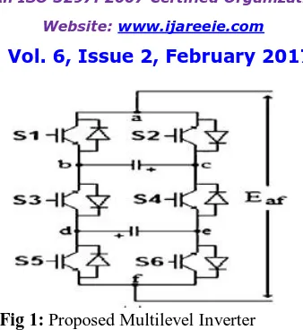
The proposed and conventional H-bridge converters are given inFig. 1. The generation of 3 different voltage levels from switching time period and the circulation of alternating current through the devices is shown in Fig. 1. Proposed converter topology requires two separated DC link capacitor for 5 level output voltage similar to cascaded multilevel converter.
The features of multilevel inverter as follows:-
It can generate output voltages with extremely low distortion and lower dv/dt.
It draw input current with very low distortion.
It generate smaller common mode (CM) voltage and reducing the stress in the motor bearings. In addition, using sophisticated modulation methods, CM voltages can be eliminated.
It can operate with a lower switching frequency.
…….. (1)
Vn is the amplitude of voltage harmonic of nth order Vdc is the DC voltage across the capacitor
N is the number of the bridges in each phase n is the odd harmonic order ϴk is the switching angle of the single phase bridge
Fig 1: Proposed Multilevel Inverter
2.1 MULTICARRIER PWM TECHNIQUES
PWM techniques entail the natural sampling of a single modulating or reference waveform typically being sinusoidal same as that of output frequency of the inversion system, through several carrier signals typically being triangular waveforms of higher frequencies.
A. Alterative Phase Opposition Disposition (APOD)
This technique requires each of the (m – 1) carrier waveforms, for an m-level phase waveform, to be phase displaced from each other alternately as shown in Figure 2.3. The most significant harmonics are centred as sidebands around the carrier frequency fc and therefore no harmonics occur at fc.
B. Phase Opposition Dispositions (POD)
The carrier waveforms are all in phase above and below the zero reference value however, there is 1800 phase shift between the ones above and below zero respectively as shown in Figure. The significant harmonics, once again, are located around the carrier frequency fc for both the phase and line voltage waveforms. The three disposition PWM techniques that are APOD, PD and POD generate similar phase and line voltage waveforms. Furthermore, for all of them, the decision signals have average frequency much lower than the carrier frequency.
2.2 SELECTIVE HARMONIC ELIMINATION
The Selective Harmonic Elimination Stepped Waveform (SHESW) technique is very suitable for a multilevel inverter circuit. Employing this technique along with the multilevel topology, the low Total Harmonic Distortion THD output waveform without any filter circuit is possible.
After applying Fourier theory to the output voltage waveform of multilevel converters, which is odd quarter wave symmetric, we can find the Fourier expression of the multilevel output voltage. If the DC voltages are equal in the multilevel converter, the equation for the fundamental frequency switching control method can be expressed as:
….. (2)
From the equation, it can be seen that the output voltage has no even harmonics because the output voltage Waveform is odd quarter-wave symmetric. It also can be seen from (2) that the peak values of these odd harmonics are expressed
in terms of the s switching angles θ1, θ2 … and θs. Furthermore, the harmonic equations produced from are
transcendental equations.
III. CONTROL OF STATCOM
Controlling susceptance value of STATCOM A steady state analysis using the phasor relations between phase voltages and phase current at fundamental frequency yields a single phase equivalent circuit for STATCOM .Here, Vais the rms value of supply voltage, Eaf is the rms value of STATCOM voltage, L is coupling (switching) inductance and R is internal resistance of inductance. The inductor takes the instantaneous voltage difference between supply and STATCOM voltages. Its inductance and resistance values are important parameters on the dynamic response of STATCOM during transient and steady-state operation. The magnitude of current by neglecting phase difference between Va and Eaf.
The susceptance of system varies according to the ratio between STATCOM voltage and source voltage as it is clearly observed. Therefore, by changing the voltage at AC side of the STATCOM, the susceptance value may be controlled from positive to negative values.
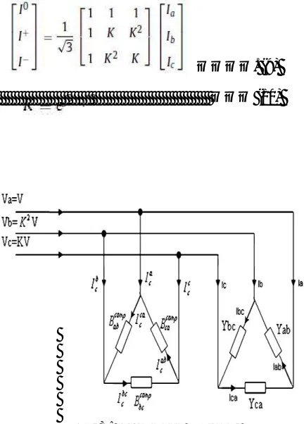
Reactive power compensation and load balancing Reactive compensation and active power balancing in a three-phase power system are performed by estimating the value of load susceptance. If the load impedance per phase of a delta-connected Fig.6. Parallel connected compensation susceptance in delta connection load or delta equivalence of any three-phase load is known then the reactive power compensation and load balancing can be successfully obtained.
………. (3)
……… (4)
……….. (5)
Equation are given above (3),(4),(5) Imaginary part of the load admittances jBab, jBbc, jBcacan be eliminated by connecting the parallel compensation susceptances at the values of jBab, jBbc, jBca, respectively. These susceptances can be created by STATCOM connected in parallel to the load. After compensating the imaginary part of the load, the unbalanced real part remains at unity power factor. Therefore, a three phase unbalanced load without the ground connection (three wire system) is converted to the balanced three phase resistive load by connecting parallel STATCOM. The susceptances injected by the STATCOM. For load balancing and reactive power compensation under this condition are given below for the supply voltages having only positive sequence components.
………. (6)
……….. (7)
……… (8)
compensation technique requires the positive, negative and zero sequence components of the load and STATCOM currents. The symmetrical components of current through the compensator and load can be obtained from the following equation:
…………. (9)
……… (10)
Fig 3: susceptance matching
The STATCOM can generate or absorb the reactive power depending on sign of susceptance load or delta equivalence of any three-phase load is known then the reactive power compensation and load balancing can be successfully obtained.
... (11)
IV. SIMULATION RESULTS
4.1 SIMULATION DIAGRAM FOR WITHOUT STATCOM
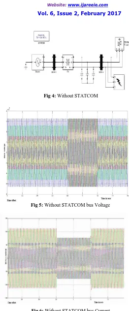
Fig 4: Without STATCOM
Fig 5: Without STATCOM bus Voltage
The voltage waveforms for without STATCOM is shown in fig.6.3.Under normal condition, the transmission line voltages are at rated nominal value. There is no power quality problems such as sag, swell, voltage interruption, etc. The magnitude of the voltage level is constant throughout the interval.
4.2 SIMULATION DIAGRAM FOR WITH STATCOM
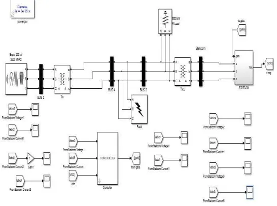
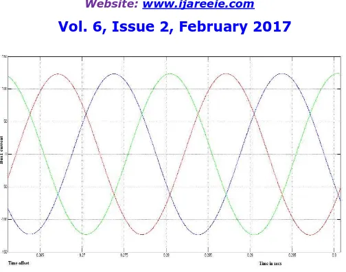
The fig.7 shows proposed systemt with STATCOM .The three phase voltage of 60 KV and current at bus in 120A a transmission line after gets compensated by STATCOM with the Carrier based phase shifted PWM technique. Thus a perfect three phase sinusoidal voltage and currents are obtained with the usage of shunt compensation device, namely the STATCOM.
Fig 7: Proposed system with STATCOM
Fig 9 : With STATCOM current
V. CONCLUSION
Thus the multilevel inverter circuit topologies (5-level) each MLI has its own mixture of advantages and disadvantages and for any one particular application, one topology will be more appropriate than the others. Often, topologies are chosen based on what has gone before, even if that topology may not be the best choice for the application. The advantages of the body of research and familiarity within the engineering community may outweigh other technical disadvantages. Multilevel converters can achieve an effective increase in overall switch frequency through the cancellation of the lowest order switch frequency terms. Although this dissertation has covered most of the interesting issues and challenges of the Cascaded multi-level inverter in many applications. Additional work has been left for future research where a prototype model will be developed; testing and validation will be carried for the developed model.
The performance of proposed converter has been evaluated on delta connected STATCOM controlled by the SPWM method underbalanced and unbalanced loads. The load balancing has been carried out by using impedance matching method which is generally used on thyristor controlled static var compensations. The entire system is simulated in MATLAB/Simulink and implemented and the gates of the IGBTs in proposed AC/DC converter can be controlled from the PWM output ports of microcontrollers that control the conventional H - bridge structure. The complementary operation of power switches have been retained in the proposed converter. This converter reduces solid state devices and their drive circuits effectively. It is an alternative converter for energy storage systems, active power filters and reactive power compensations.
REFERENCES
[1] Maiyarasu.D, Gopinath.S,A New Topology of Hybrid Multilevel Inverter‖ in International Journal of Engineering Sciences & Research Technology [1509-1513] June, 2013.
[2] J. S. Lai and F. Z. Peng, “Multilevel converters – A new breed of power converters,” IEEE Trans. Ind. Applicat., vol. 32, pp. 1098– 1107, May/June 1996.
[3] J. Rodriguez, J.-S. Lai, and F. Z. Peng, "Multilevel inverters: a survey of topologies, controls, and applications," IEEE Trans. Ind. Electron., vol. 49, pp. 724-738, 2002.
[4] L. M. Tolbert, F. Z. Peng, and T. G. Habetler, "Multilevel converters for large electric drives," IEEE Trans. Ind. Applicat., vol. 35, pp. 36-44, 1999.
[5] M. F. Escalante, J. C. Vannier, and A. Arzande “Flying Capacitor Multilevel Inverters and DTC Motor Drive Applications,” IEEE Transactions on Industry Electronics, vol. 49, no. 4, Aug. 2002, pp. 809-815.
[6] L. M. Tolbert, F. Z. Peng, “Multilevel Converters as a Utility Interface for Renewable Energy Systems,” in Proceedings of 2000 IEEE Power Engineering Society Summer Meeting, pp. 1271-1274.
[8] L. M. Tolbert, F. Z. Peng, T. G. Habetler, “A Multilevel Converter-Based Universal Power Conditioner,” IEEE Transactions on Industry Applications, vol. 36, no. 2, Mar./Apr. 2000 pp.596-603.
[9] L. M. Tolbert, F. Z. Peng, T. G. Habetler, “Multilevel Inverters for Electric Vehicle Applications,” IEEE Workshop on Power Electronics in Transportation, Oct 22-23, 1998, Dearborn, Michigan, pp. 1424-1.
