Power Quality improvement by using
DSTATCOM in power distribution system fed
BLDC motor
P.VINAY BABU
PG scholar, Department of EEE, St. Ann’s college of Engineering & Technology, Chirala, A.P, India.
Mail id: [email protected].
S.V.D.ANIL KUMAR
Associate Professor& HOD,Department of EEE, St.Ann’s College of Engineering and Technology,
Chirala , A.P, India.
Mail id:[email protected].
Abstract:
A Power
quality
problem is
an
occurrencemanifested as a nonstandard voltage,
current or frequencythat results in a failure or a miss
operation of end userequipment’s. Utility distribution
networks, sensitiveindustrial loads and critical
commercial operations sufferfrom various types of
outages and service interruptionswhich can cost
significant financial losses. With therestructuring of
power systems and with shifting trendtowards
distributed and dispersed generation, the issue
ofpower quality. Utility distribution networks,
sensitiveindustrial loads and critical commercial
operations sufferfrom various types of outages and
service interruptionswhich can cost significant
financial losses.Distribution static compensator
DSTATCOM) is ashunt compensation device that is
generally used tosolve power quality problems in
distribution systems. DSTATCOMforces load to
operate always at rated power. Hence,customers need
to pay for constant power continuously,whereas rated
heating losses will take place in theequipments for
entire operation. This concept proposes a hybrid
control algorithm to maximize utilization and
functionality
of
distribution
staticcompensator
(DSTATCOM). In this paper,implementing Power
quality circuit with voltagesource converter in the
BLDC Motor drive isdeveloped. The control of BLDC
drive used is FieldOriented Control using pulse with
Modulation. Thepower quality circuit proposed here
improves thepower factor and reduces harmonic
distortion.Simulation work is performed using
MATLAB /SIMULINK environment.
Key Words:
DSTATCOM, power Quality, BLDC
motor, Distribution Generation.
I INTRODUCTION
Electric power distribution network havebecome
more increasingly important and plays anessential
role in power system planning. This type ofpower
systems has a major function to servedistributed
customer loads along a feeder line;therefore under
competitive environment ofelectricity market service
of electric energy transfermust not be interrupted and
at the same time theremust provide reliable, stable
and high quality ofelectric power [1-2].However,one
might consider an additional device to beinstalled
somewhere in the network. Such devicesare one of
capacitor bank, shunt reactor, seriesreactors [3-4], and
automatic
voltage
regulators
and/orrecently
developed dynamic voltage restorers,distribution
static compensator (DSTATCOM), orcombination of
them [5-6]. The DSTATCOM [9-10]is a voltage
source
converter
(VSC)
based
custompower
technology which can perform as a reactivepower
source in power systems. The D-STATCOM[7] can
regulate magnitude of voltage at a particular ACbus,
at the point where it is connected, via generatingor
absorbing reactive power from the system.
thyristor-switched capacitors.
In present day distribution systems (DS), major
powerconsumption has been in reactive loads. The
typicalloads may be computer loads, lighting ballasts,
smallrating adjustable speeds drives (ASD) in
airconditioners, fans, refrigerators, pumps and
otherdomestic and commercial appliances are
generallybehaved as nonlinear loads [9-10]. These
loads
draw
laggingpower-factor
currents
and
therefore give rise toreactive power burden in the DS.
Moreover, situationworsens in the presence of
unbalanced and non-linearloads, affect the quality of
source currents to a largeextent. It affects the voltage
at point of commoncoupling (PCC) where the facility
is connected. Thishas adverse effects on the sensitive
equipmentsconnected to PCC and may damage the
equipmentappliances [11].
In this paper, a hybrid control scheme has been
proposed to maximize the DSTATCOM utilization
while considering the above mentioned issues.
Instantaneous symmetrical component theory, with
flexibility of choosing pf, is used to compute
reference source currents [12]. The reference load
voltages are computed such that the least allowable pf
is maintained at the PCC. Consequently, load power
is appropriately controlled and advantages of energy
conservation are also achieved. If reference load
voltage at the predefined minimum pf comes less than
the lowest allowable operating voltage, then pf is
improved to get new reference load voltage.
Therefore, proposed scheme ensures that energy
conservation is achieved while drawing allowable
reactive power from the source.
The BLDC Motor used to make low power
ratingapplication devices such as Refrigerator,
WashingMachine, House-hold appliances, Medical
Equipment,Wide speed range of servo drives and
industrial robots.BLDC drives are used for its high
efficiency, fast dynamic response and small size etc.
For the operationof BLDC Drive first need to convert
AC supply powerto DC power using rectifier circuit
and then DC powerto variable magnitude and variable
frequency ACpower to feed BLDC.
II SYSTEMDESCRIPTION
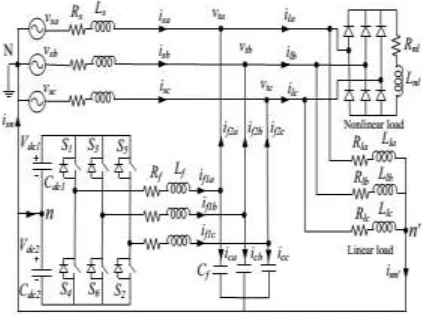
Circuit configuration of a DSTATCOM, as shown in
Fig.1, is connected at the PCC in a three-phase
four-wire distribution system.vsj, vtj, isj, and ilj are source
voltage, load voltage, source current, and load current
respectively, where j=a, b, c represent phases. Rs and
The load consists of a diode rectifier feeding an RL
load
plus
an
unbalanced
linear
load.
The
DSTATCOM uses two-level, neutral-point-clamped
VSI topology due to its ability to control the
operation of each VSI leg independently. The dc link
capacitors are represented by Cdc1 =Cdc2 = Cdc,
whereas the voltages maintained across them are
Vdc1= Vdc2=Vdc=Vdcref. An LC filter is used at the front
end of VSI to achieve an appropriate output voltage at
the PCC.
Fig 1 DSTATCOM configuration in a distribution system
III
PROPOSEDHYBRIDCONTROLALGORITHM
Objective of proposed hybrid control algorithm based
DSTATCOM is to reduce the voltage and current
harmonics, balance the source currents, improve the
pf, compensate for voltage disturbances such as sag
and swell, reduce the losses in VSI, reduce the rating
of VSI, and control the load power for energy
conservation while analyzing their effects on the
consumers.
During normal operating conditions, at which system
operates most of the time, it is desired that harmonic
component of load current is supplied by the filter.
Additionally, pf at the PCC is maintained in such a
way that the penalty for reactive power drawn from
the source is avoided. In literature, several reference
generation schemes have been proposed. In this
paper, instantaneous symmetrical component theory
(ISCT) based algorithm is used for computation of
reference source currents due to its flexibility in
achieving desired pf [11]. Following three conditions
are simultaneously satisfied while using ISCT based
algorithm:
(1)
2. A definite angle (φvi+) between fundamental
positive sequence load voltage and source current (vta1+
and ila1+respectively) is maintained. Considering for
phase-a
(2) 3. Source must supply average load power (Plavg) and
VSI losses (Ploss). Source power is given as
(3) where
(4) Solving (3.1), (3.2), and (3.3) expressions for reference source currents are given as follows:
(5) Where
The phase-a load voltage and source current are given as follows:
(6) Phase-a source voltage is given as
(7) Applying Kirchhoff’s voltage law between source and load points
(8)
Fig2 Proposed hybrid control algorithm for reference load voltage generation
Using (6) and (7) in (8), we have
(9)
Where and
Equating real and reactive part in both the sides of above equation
(10) Squaring and adding the above equation
(11) Finally, load voltage will be
(12) With balanced supply, computed rms load voltage will be same for all three-phases and it will be used as Vt
for further explanations. Once the expression for load voltage from above equation is computed, reference load voltage magnitude for several DSTATCOM operating conditions will be developed. The flow chart of choosing the suitable reference load voltage is given in Fig.2 and explained as follows.
a)Source Voltage Is Less Than 0.9 Pu:
DSTATCOM, load voltage is maintained at 1.0 pu during sag. It results in more current injection by the VSI, increased losses in VSI, and rated power drawn by the load. In this paper, the reference load voltage is set at 0.9 pu during voltage sag. At this voltage, following features are obtained
i. Load will remain operational even during voltage disturbances.
ii. Load will draw minimum power, as compared to rated power in conventional DSTATCOM operating in VCM. iii. Filter current will less compared to conventional VCM operation. Hence, VSI losses will decrease and so, efficiency will increase. Moreover, size of VSI can be reduced due to reduced current requirement.
b)Source Voltage Is Greater Than 0.9 Pu:
When source voltage is greater than 0.9 pu, then it is necessary to find appropriate reference load voltage. Conventional CCM operation of DSTATCOM maintains UPF at the PCC. Usually, most of the utilities permit customers to draw allowable reactive power without paying for tariff (however, it may vary depending upon customers). Therefore, from customer point of view, it is not necessary to maintain UPF at PCC. In proposed scheme, we have considered that the customers are allowed to operate load up to 0.9pfwithout any penalty. Keeping this into account, reference source currents are calculated using instantaneous symmetrical component theory at a pf of 0.9. i.e., β= 0.28. With this source current, load voltage is calculated using (12). At this voltage, following conditions are possible:
1) Vta is Less Than 0.9 pu: This voltage is computed at the
lowest permissible value of pf. But, improvement in pf will
increase the load voltage. Therefore, pf is improved in a fixed step of 0.05 from previous value of 0.9 pu and modified reference source currents are again computed using (5). For this current, modified load voltage is computed. If this voltage becomes greater than 0.9 pu then same voltage is used as reference load voltage. This method gives following advantages:
i. Source currents will be balanced and sinusoidal.
ii. Reduced currents are supplied by the filter compared to conventional CCM operation. Therefore, VSI losses decrease and its efficiency increases.
iii. Load voltage is lesser compared to conventional CCM operation. Hence, power drawn by the load will decrease. It will reduce the power tariff, reduce the heating loss, and increase the device life.
However, if the load voltage is not more than 0.9 pu, then above process is repeated until the load voltage becomes more than 0.9 pu. But, there must be a limit on the value of pf that can be achieved. Our objective is to
keep load operational by keeping load voltage within the permissible range, while ensuring that allowable amount of reactive current is also drawn from the source. Importantly,
CCM operation if pf is set to leading. It will force load to
draw additional real power. Therefore, maximum pf is
limited to 1.0. If load voltage does not become greater than 0.9 pu with this pf, then a flat voltage of 0.9 pu is set as
reference load voltage.
2) Vta is Less Than 1.0 pu: This is the normal operating conditions as load voltage lies between 0.9 pu to 1.0 pu, where system operates most of the time. The reference load voltage is set at a value obtained from (12). This voltage will indirectly control the source currents and maintains 0.9
pf at the PCC. Therefore, operation of proposed scheme in
this case will be similar to conventional CCM operation of DSTATCOM. However, following additional advantages are achieved in proposed scheme:
i. Predefined minimum pf is maintained at the PCC by the
compensator. Hence, filter currents are reduced.
Consequently, VSI losses decreases and its efficiency increases.
ii. The least pfat PCC makes load voltage lesser compared
to conventional DSTATCOM operating in CCM. Hence, power drawn by the source decreases. It reduces the power tariff, reduce the heating loss, and increase the device life.
3) Vta is Greater Than 1.0 pu: Maintaining load voltage at a value greater than 1.0 pu forces load to draw more power than the rated power. Further, filter will have to supply more reactive current to maintain this voltage. If load voltage comes more than 1.0 pu, then source voltage
is also more than 1.0 pu. This voltage is computed at a pf of
0.9. If load voltage does not become less than 1.0 even for 0.9pf, a flat voltage of 1.0 is set as reference voltage. In this case, performance of DSTATCOM and load in proposed scheme will be same as that of conventional DSTATCOM operating in VCM.
IV BLDC MOTOR
Fig.3. BLDC motor stator construction
Fig.4. BLDC motor Rotor construction.
The brush less dc engine comprise of four fundamental parts Power converter, changeless magnet brushless DC Motor (BLDCM), sensors and control calculation. The force converter changes power from the source to the BLDCM which thus changes over electrical vitality to mechanical vitality. One of the remarkable highlights of the brush less dc engine is the rotor position sensors, in view of the rotor position and order signals which may be a torque charge, voltage summon, rate order etc; the control calculation s focus the entryway sign to every semiconductor in the force electronic converter.
The structure of the control calculations decides the sort of the brush less dc engine of which there are two principle classes voltage source based drives and current source based drives. Both voltage source and current source based commute utilized for perpetual magnet brushless DC machine. The back emf waveform of the engine is demonstrated in the fig.5. Be that as it may, machine with a non sinusoidal back emf brings about diminishment in the inverter size and lessens misfortunes for the same influence level.
Fig.5. Hall signals & Stator voltages.
V MATLAB/SIMULINK MODEL
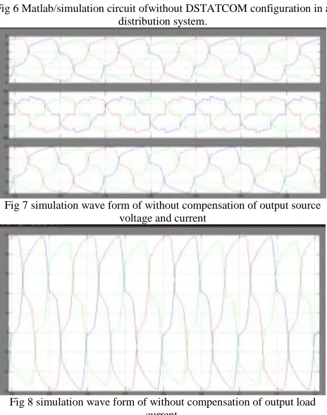
Fig 6 Matlab/simulation circuit ofwithout DSTATCOM configuration in a distribution system.
Fig 7 simulation wave form of without compensation of output source voltage and current
Fig 9 Matlab/simulation circuit of with DSTATCOM configuration in a distribution system.
Fig 10 simulation wave form of source voltage and current
Fig 11 simulation wave form of dc voltage.
Fig 12 simulation wave form of filtering voltage.
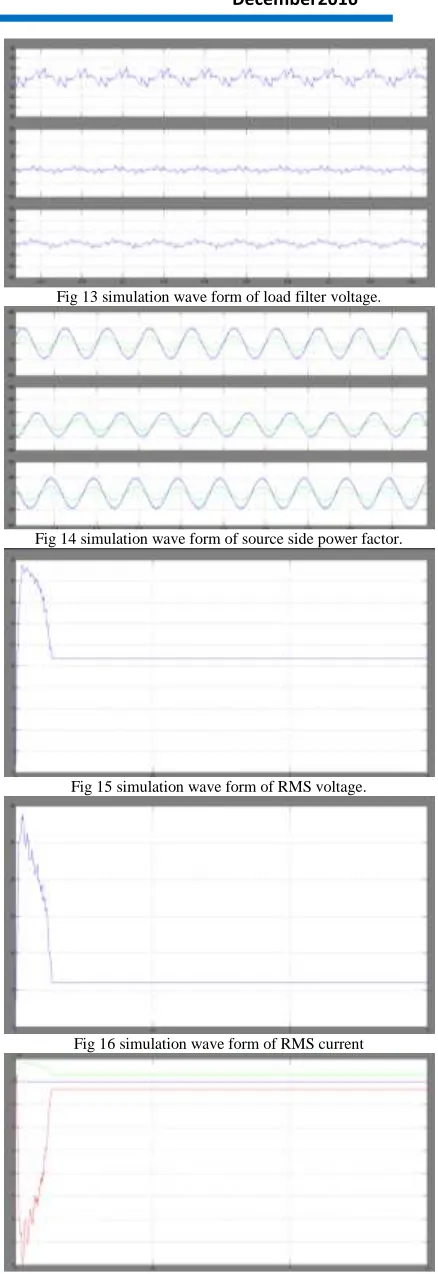
Fig 13 simulation wave form of load filter voltage.
Fig 14 simulation wave form of source side power factor.
Fig 15 simulation wave form of RMS voltage.
Fig 16 simulation wave form of RMS current
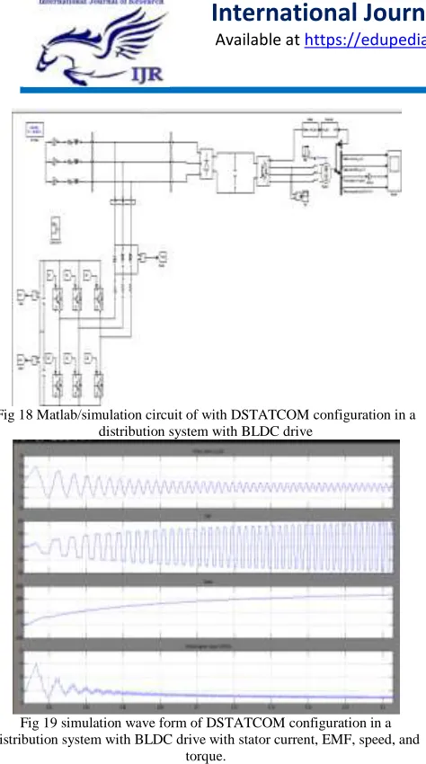
Fig 18 Matlab/simulation circuit of with DSTATCOM configuration in a distribution system with BLDC drive
Fig 19 simulation wave form of DSTATCOM configuration in a distribution system with BLDC drive with stator current, EMF, speed, and
torque. V CONCLUSION
A new hybrid DSTATCOM with reduced dc-linkvoltage has been discussed in detail which has theability to
compensate the load improving power qualityof
distribution system. Design of various parametersand control theories involved in this study wereexplained.In this paper, a control algorithm has been proposedfor the generation of reference load voltage for avoltage-controlled DSTATCOM. The performance ofthe proposed scheme is
compared with the traditionalvoltage-controlled
DSTATCOM.This scheme notonly provides several PQ improvement features but alsoreduces load real and reactive power, filter currentrequirement to achieve desired compensation performance,and leads to reduction in the size of VSI. Extensivesimulation studies validate effectiveness of the proposedBLDC drive to study the characteristics, and to achievinggood performance.
REFERENCES
[1] J. A. Momoh, Electric Power Distribution, Automation, Protection and Control, New York, USA: CRC Press, 2008.
[2] N. G. Hingorani and L. GyuGyi, Understanding FACTS Concept and Technology of Flexible AC transmission System, New York, USA: IEEE Press, 2000. [3] N. G. Hingorani, “Introducing custom power”, IEEE Spectrum, June1995, pp. 41– 48.
[4] A. Ghosh and G. Ledwich, Power quality enhancement using custom power devices, Massachusetts, USA: Kluwer Academic Publishers,2002.
[5] A.L. Olimpo and E. Acha, “Modeling and analysis of custom power systems by PSCAD/EMTDC,” IEEE Trans. Power Delivery, vol. 17, no.1, pp. 266-272, Jan. 2002. [6] P. Pohjanheimo and E. Lakervi, “Steady state modeling of custom power components in power distribution networks,” in Proc. IEEE Power Engineering Society winter Meeting, vol. 4, Jan. 2000, pp. 2949- 2954.
[7] P. Mitra and G. Venayagamoorthy, “An adaptive control strategy for DSTATCOM applications in an electric ship power system,”IEEE Trans. Power Electron., vol. 25, no. 1, pp. 95–104, Jan. 2010.
[8] A. Yazdani, M. Crow, and J. Guo, “An improved nonlinear D-STATCOM control for electric arc furnace voltage flicker mitigation,” IEEE Trans. Power Del., vol. 24, no. 4, pp. 2284–2290, Oct. 2009.
[9] Srinivas BK, Nagesh G, Mahesh KM, BK Kumar, “A DSTATCOM topology with reduced dc-link voltage rating for load compensation with non stiff sources”, IEEE Trans. Power Elec., vol. 27, no. 3, March. 2012
[10] A. Ghosh and A. Joshi, “A new approach to load balancing and power factor correction in power distribution system,” IEEE Trans. Power Del., vol. 15, no. 1, pp. 417– 422, Jan.2000.
[11] H. Akagi and R. Kondo, “A transformer less hybrid active filter using a three-level pulse width modulation (PWM) converter for a medium voltage motor drive,” IEEE Trans. Power Electron., vol. 25, no. 6, pp. 1365– 1374, Jun. 2010.