www.ijiset.com
High Security Video Watermarking Using Block Tree Coding
Algorithm
R.Vinothkumar1, V.Banumathy2, R.Manikandan3
1
Assistant Professor, Department of ECE, ACET, Erode, Tamilnadu, India. [email protected]
2
Lecturer, Department of ECE, APC, Erode, Tamilnadu, India. [email protected]
3
Assistant Professor, Department of CSE, ACET, Erode, Tamilnadu, India. [email protected]
Abstract
Ownership is a most problem when the data Owners Outsource data storage or processing to a third party Computing service, such as the cloud. In this paper we explain Discrete Wavelet Transform method by using Block Tree Coding Algorithm to achieving Secure watermark detection. In the transmission side we Applying the Gaussian Filter for Pre-processing, then using Multi Wavelet Block Tree Coding Algorithm to Embed the Secret data to the Image and it will converted in to bit streams. In the receiver side Image and Secret data are split by applying the Inverse Multi Wavelet Block Tree Coding Algorithm. Finally we calculate MSE, PSNR values for checking the Quality of the Secret data, and compare to Discrete Cosine Transformation method.
Keywords: Discrete Cosine Transformation, Discrete Wavelet Transform, Gaussian Filter, Multi Wavelet Block Tree Coding, MSE, PSNR.
1. Introduction
Compression is a process of efficiently coding digital data to reduce the number of bits required in data. Most digital video applications involve the transmission or storage of a large amount of data. To reduce the requirements in terms of bandwidth and storage, some form of data compression is often used to transmit or store digital video. A digital video typically consist of a time ordered sequence of frames that are themselves comprised of a rectangular array of numbers called pixels. Compression is achieved through the use of a codec: a compression decompression algorithm that looks for redundancy in data files. For example, XXXYYYY could be reduced to 3X4Y. In this example, the compression is considered “lossless” because the file can be decompressed and restored to the original format without any loss of data. Video compression, however, is considered “lossy” because it results in a loss of data. When compressing video, codecs look for redundancy in areas where the human eye or ear cannot distinguish between differences. Since the human eye is less sensitive to color differences
than to brightness, the color information (chrominance) is separated from the brightness information (luminance). The codec then averages the chrominance data for adjacent pixels, which reduces the volume of data. The luminance data is not changed. Normally, individuals cannot perceive the 2 differences caused by the lossy compression. However, when the image is enlarged, the data loss is obvious, and it will look blocky.
Over the past decade, there has been an exponential increase in the demand for digital video services such as high-definition television, web based television, video conferencing and video on demand. Various video compression techniques can compact video data from 4 to 100 times smaller than its original size. The amount of reduction is dependent on the video content and the type of compression technique.
Storage and bandwidth requirements can be brought to more suitable by representing the raw digital video in a compressed form. To use compressed video data, two additional operations are needed during processing to translate the video to and from its original form. The first is encoding, which transforms the original video data into a compressed form. When the video data is needed back in its original form, a decoding operation recovers the data, which is sometimes an inversion of the encoding process.
Advances realized in the fields of network, telecommunications and digital storage are not sufficient to utilize the digital data. Among all these data to store or to transmit, multimedia data have an increasing place. The data represented by digital video (high definition digital television, digital cinema, vision conference, internet or mobile communications) are particularly inclined to frequent and often pointless change. But the problem of storage is not the only problem linked with the explosion of digital video. For all of these reasons, compression has become an essential step in most of the applications linked with digital video. Due to the increased interest in multi-media applications, and the growing use of digital video for education and entertainment, it is desirable to find
www.ijiset.com waysof delivering real-time video on computer. Asimage compression is now a somewhat mature subject . In particular, the increasing number of services and growing popularity of high definition videos are creating much more need for higher coding efficiency. A fundamental figure of merit for a video coding design is its compression capability, which is also referred to as its coding efficiency. The coding efficiency relationship between two designs is typically best expressed in terms of percentage savings in bit rate for equal subjective perceptual quality.
In addition to enabling service providers to deliver more content at a given, improved coding efficiency can alternatively be used to provide higher quality video (e.g., higher resolution or less distorted video) at a given bit rate, or to provide some other improved balance between bit rate and video quality. Improved coding efficiency can be a compelling advantage. High efficiency video coding (HEVC) [1] is the currently prepared new video coding standard , which provides significantly better compression capability than the existing AVC (ITU-T H.264 | ISO/IEC MPEG-4 Part 10) standard .
In this paper, proposed multiwavelet block tree encoding algorithm is applied to achieve high efficiency video compression. The wavelet block tree encoding algorithm overhands the set partitioning in hierarchical tree encoding technique by reducing the bit rate.
The paper is organized as follows. In Section II the steps of the proposed approach are described in details with multiwavelet block tree encoding algorithm. In Section III, , the methodology of performance evaluation and the experimental results are given. Section IV, concludes the paper with the possible future work of the proposed method.
2. Proposed Work:
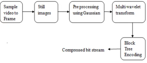
An overview of the basic operations in a proposed video encoder is shown in Figure 1 .The encoder takes in an unprocessed input video sequence, called the original video sequence, compresses it, and transmits the resulting representation, called the bit stream, to the decoder. The decoder receives the compressed bit stream and reconstructs a best approximation of the original sequence, which is called the reconstructed sequence.
The input video sequence is represented by a discrete series of frames. Each frame represent an instance of time in the video, which, when displayed alongside its neighbours, can give the illusion of a continuously changing sequence. Each frame in the video sequence is in turn composed of a two-dimensional array of pixels. Each pixel represents information at a particular point in space.
When combined together at a fine enough resolution, an array of pixels gives the illusion of a continuous-tone image. The pixels of a video frame
represent either a single intensity value (for black and white images) or a multi-intensity color value.
There are three main components in the proposed video encoder: Pre-processing using Gaussian filter, Multiwavelet transform and block tree encoder. The multiwavelet transform and block tree encoder all account for pixel relationships within a frame. For this reason, when the frame is being encoded, the motion estimator is not utilized. These proposed algorithms primarily target the improved processing of frames in the encoder. Therefore, all three encoder components are very important. This section describes the basic function of these three components, beginning with the pre-processing using Gaussian filters.
Fig.1 Block Diagram of Proposed Video Encoder
2.1 Pre-processing Using Gaussian Filters
Key functions of pre-processing are to improve the quality of image in various ways that increase the chances for success of other process. Generally filters are used to filter unwanted things or object in a spatial domain or surface. In digital image processing, mostly the images are affected by various noises. The main objectives of the filters are to improve the quality of image by enhancing. Low- pass filter is a type of filter used for the image enhancement. It preserves the smooth region in the image and removes the sharp variation leading to blurring effect.
The frequency domain technique is based on the convolution theorem. It decomposes an image from its spatial domain form of brightness into frequency domain components and is represented as the following equation
Where f(x,y) is the input image ,h (x,y) is a position invariant operator and g(x,y)is the resultant image from the convolution theorem. G, H, F are the Fourier transform of g,h,f respectively. The transform H(u,v) is called transfer function of the process.
Here in this work, Gaussian filters [2] are used to remove the noise and smoothing of images. The Gaussian filters works by using the 2D distribution as a point-spread function. This is achieved by convolving the 2D Gaussian distribution function with the image. The Gaussian smoothing filter is very good in noise removal in normal
www.ijiset.com distribution function. This filter is rotationally symmetric the amount of smoothening in all direction.
It is not particularly effective at removing salt and pepper noise. The Gaussian filter is a non-uniform low pass filter. Central pixels have a higher weighting than those on the periphery. Larger values of σ produce a wider peak (greater blurring). Kernel size must increase with increasing σ(standard deviation) to maintain the Gaussian nature of the filter. Gaussian kernel coefficients depend on the value of σ. At the edge of the mask, coefficients must be close to 0. The kernel is rotationally symmetric with no directional bias. Gaussian kernel is separable which allows fast computation separable. Gaussian filters might not preserve image brightness.
2.2 Overview of Multiwavelets
The objective of a video compression algorithm is to exploit both the spatial and temporal redundancy of a video sequence such that fewer bits can be used to represent the video sequence at an acceptable visual distortion. Removing the spatial redundancy within a frame is called as intraframe coding. Normally I frames are coded in this way. This is achieved using transform. There are many transforms like ‘DCT’, ‘DWT’, and Multiwavelet transform [3]-[4].
Multiwavelets [5]-[6] have more than one mother wavelet functions and scaling functions. Multiwavelets are the extension of scalar wavelets. In multiwavelets, multiresolution analysis is carried out using several scaling and wavelet functions. A multiwavelet with ‘r’ scaling and ‘r’ wavelet functions is said to have multiplicity ‘r’.
When r =1, one scaling function and one wavelet function, the multiwavelet system to reduce to the popular scalar wavelet systems. Multiwavelets have several advantages in comparison with scalar wavelet. The multiwavelets satisfy simultaneously linear-phase symmetry, orthogonality, compact support and approximation order k>1, which is not possible with 2D scalar wavelets. These desirable properties are highly useful in designing multiwavelet based discrete signal analysis and synthesis.
Let H[k] and G[k] be their N×N impulse response constant matrices. Let
(1)
(2)
be the multiscaling and multiwavelet functions,
respectively.
The scaling space is given by,
(3)
And wavelet space is given by,
(4)
The multiscaling and multiwavelet function is respectively given by the matrix dilation and wavelet equation as given in equation (5) and (6).
(5)
(6)
Where, H is the matrix low pass filter and G is matrix high pass filter.
Corresponding to each multiwavelet system, there is a matrix valued multirate filter bank. Figure 2 shows filter bank corresponding to multiwavelet system for analysis and synthesis. In multiwavelet system, the low pass filter H and high pass filter G coefficients are r×r matrices. If coefficients s0- are input to the analysis section of the filter bank at scale level zero, one iteration computes the coarse vector coefficients s-1-1 and the detail vector coefficients d-1
-1
at scale 2-1 as given in equation (7) and (8), respectively. This is the discrete multiwavelet decomposition [7].
Fig.2 Multi wavelet Filter Bank: Analysis and Synthesis Stages
(7)
(8)
This means that multifilter banks need r input rows. In frequency domain, the matrix frequency responses for the H and G be denoted by H(ω) and G(ω) respectively.
2.3 Multiwavelet Decomposition
The decomposition procedure and structure for multiwavelet decomposition differs from scalar wavelet decomposition since they possesses two low pass subbands corresponding to two scaling functions and two high pass subbands corresponding to two wavelet functions in each dimension. Scalar wavelet frequently fails to capture
www.ijiset.com frequency information accurately. Multiwavelet decomposition algorithm is used to preserve the high frequency information during decomposition.
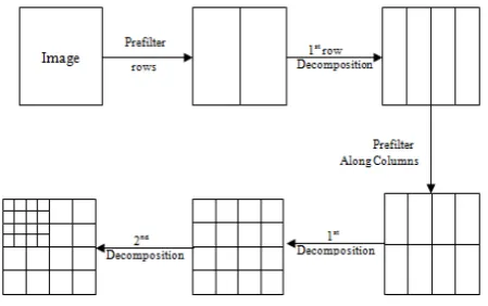
Using the idea of separable decomposition along each dimension of a 2D image, the preprocessing is carried out, first along rows by taking the tensor products of the prefilter with 2D images followed by multiwavelet decomposition along rows as per the multiwavelet decomposition algorithm detailed in following subsection. The same process of prefiltering and first level vector valued decomposition is then performed on the resulting transformed image, but now along the columns. This completes one level of decomposition. This is illustrated in Figure 3.
The low pass filters H and high pass filter G in the multiwavelet filter bank is 2×2 matrices. Thus, they need to be convolved with two rows of data. However, for 1-D signals, we have only one row of data; so we have to pre-process the 1-D signal to obtain two rows of data. We note that, the pre filtering should not destroy orthogonality and/or symmetry of the bases. One solution to this problem is simply to repeat the input.
Fig. 3 Two Level Multiwavelet Decomposition of a 2D Image Filtering
2.4 Multiwavelet Block Tree Coding
The wavelet block tree coding for scalar wavelet decomposed images, which combines the features of both zero tree coding algorithm like SPIHT [8] and zero block coding algorithm like Set Partitioning Embedded block (SPECK) to provide inter and intra subband correlation. The WBTC [10] overhands the SPIHT in three aspects: first it creates zero trees with more elements. Second it strengthens the intra subband correlation and thirdly it reduces the encoding time. However its efficiency can be fully signified only when applied to multiwavelet transformed data.
This motivates to apply block tree coding to multiwavelet transformed image and for the first time applied this to Multiwavelet transformed image. The
proposed MBTC algorithm partitions the image transformed coefficients into coefficient blocks and then block trees are formed with the roots in the topmost subband in a zero tree fashion. In a block tree, significant blocks are found using the tree partitioning concept of SPIHT [9], whereas significant coefficients within each block are found using the quad-tree partitioning of SPECK.
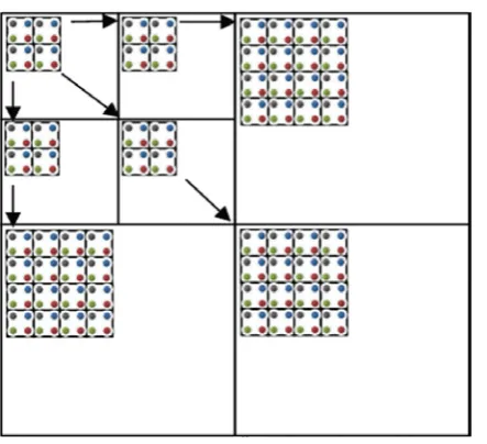
Consider an image X of size MxN that after Nd levels of wavelet transformation exhibits a pyramidal subband structure. The transformed image is represented by an indexed set of transformed coefficients {Ci,j} located at ith row and jth column. The coefficients are grouped together in blocks of size mxn and the block trees are formed with roots in the topmost (LL) subband. A block tree is a tree of all descendent blocks of a root block. Figure 4 Wavelet Block Tree coding.
In the LL band, out of each group of 2x2 blocks, one (top left) block has no descendent, and each of the other three blocks has four offspring blocks in the high frequency subbands of their corresponding orientations. By creating block tree, many of the SPIHT’s SOTs are combined into a single MBTC’s SOT. Let us define a significant function, s (.) in the bth most significant bit plane applied to set T as
Sb(T)=({1,max |ci,j|}) ≥ 2P
b
P
,CRi,jRϵ T
0, Otherwise
Where set T may either be an individual block of mxn wavelet coefficients or SOT of a block. Like SPIHT, MBTC maintains three ordered lists.
LIB : List of Insignificant Blocks.
LIBS : List of Insignificant Block Sets.
LSP : List of Significant Pixels. For each bit plane MBTC consists two main stages sorting pass and refinement pass. At the initialization step, the block in the lowest frequency band are added to LIB and those with the descendent are added to LIBS as type ‘A’ entries. The scanning starts with LSP as an empty set. The coding process starts with the coarsest resolution and proceeds towards the finest resolution.
www.ijiset.com
Fig. 4 Wavelet Block Tree Coding
In the sorting pass the encoder checks the blocks in the LIB list against the current threshold. For each block it generates one bit i.e. it generates ‘0’ for zero block or insignificant block and ‘1’ for nonzero block or significant block. Thus m x n insignificant block is just encoded with single bit whereas in SPIHT it uses m x n ‘0’ bits. Thus in addition to providing bit reduction it also provides intra subband correlation.
A significant block in quad partitioned i.e. four equal size subbands are formed. This partitioning is done recursively until single coefficient is found. In this stage the individual four coefficients are tested for significance individually. The significant coefficient is encoded as ‘1’ followed by ‘0’ for positive and ‘1’ for negative sign and the coefficient is moved to LSP. After testing all the four individual coefficients, the current block is deleted from LIB.
The insignificant coefficient is encoded as ‘0’ and moved to the LSB as a single coefficient block. The encoder next examines the LIBS and performs the significance test on each set. It examines not the current block of the set but it examines the descendent blocks. In the significant block sets the four off springs are added to LIB and they are examined for significance as if they were in LIB. The scanning proceeds in the same manner for the same threshold until all the blocks are examined. The algorithm repeats with this procedure until a block size of 1 x 1 (single pixel) is met as in case of SPIHT, by reducing threshold at each level by a factor of two.
2.5 Performance Evaluation Parameters
The Robustness of the system against Gaussian white additive noise with zero mean and increasing variance can be described by using PSNR and MSE values.
2.6 SCREEN SHOTS
Fig. 5 Video to Frame Conversion
Fig. 6 Convert Colour Image to Gray scale Image
www.ijiset.com
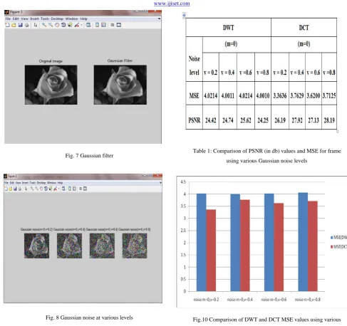
Fig. 7 Gaussian filter
Fig. 8 Gaussian noise at various levels
Fig. 9 wavelet block tree coding based watermarking
Table 1: Comparison of PSNR (in db) values and MSE for frame
using various Gaussian noise levels
Fig.10 Comparison of DWT and DCT MSE values using various
Multiwavelet filters
Fig. 11 comparison of DWT and DCT PSNR values using various
Multiwavelet filters
www.ijiset.com
Conclusion
Here experimental results show that the DWT provides high MSE, low PSNR and values compare to DCT at different Gaussian white additive Noise Levels. Investigate the proposed multiwavelet block tree encoding (MBTC) algorithm provides high efficiency for the given video sequence compared with existing DCT algorithm.
References
[1] Qia Wang, Wenjun Zeng, and Jun Tian, “A Compressive Sensing based Secure Watermark Detection and Privacy Preserving Storage Framework” IEEE Transactions On Image Processing, vol. 23, no. 3, march 2014.
[2] T. Bianchi and A. Piva, “Secure watermarking for multimedia content protection: A review of its benefits and open issues,” IEEE Signal Process. Mag., vol. 30, no. 2, pp. 87–96, may 2013.
[3] M. Davenport, P. Boufounos, M. Wakin, and R. Baraniuk , “Signal processing with compressive measurements,” IEEE J. Sel. Topics Signal Process., vol. 4, no. 2, pp. 445–460, jan 2010.
[4] D. Hsu, S. M. Kakade, J. Langford, and T. Zhang, “Multi-label prediction via compressed sensing,” in Proc. NIPS, pp. 772–780, 2009.
[5] A. Orsdemir, H. O. Altun, G. Sharma, and M. F. Bocko , “On the security and robustness of encryption via compressed sensing,” in Proc. IEEE Military Commun. Conf., pp. 1040–1046, 2008.
[6] K. Liu, H. Kargupta, and J. Ryan, “Random projection-based multiplicative data perturbation for privacy preserving distributed data mining,” IEEE Trans. Knowl. Data Eng., vol. 18, no. 1, pp. 92–106, 2006.
[7] A. Adelsbach and A. Sadeghi, “Zero-knowledge watermark detection and proof of ownership,” in Proc. 4th Int. Workshop Inf. Hiding, vol. 2137, pp. 273–288, 2001.
[8] W. Zeng and B. Liu, “A statistical watermark detection technique without using original images for resolving rightful ownerships of digital images,” IEEE Trans. Image Process., vol. 8, no. 11, pp. 1534–1548,1999.
First Author R.Vinothkumar, He has completed B.E Electronics and Communication Engineering in SSM College of Engineering, Namakkal, Tamilnadu, India in 2013. He has completed M.E Communication System in Nandha College of technology, Erode, Tamilnadu, India in 2015. He is currently working as a Assistant Professor in Aishwarya college of Engineering and technology, Erode, Tamilnadu, India. His research areas are Image Processing and Network Security.
Second Author V.Banumathy, She has completed B.E Electronics and Communication Engineering in Sree Sakthi Engineering College, Coimbatore, Tamilnadu, India in 2014. She is currently working as a Lecturer in Aishwarya Polytechnic College, Erode, Tamilnadu, India. Her research areas are Image Processing and Mobile Communication.
Third AuthorR.Manikandan, He has completed B.Tech Information Technology in SSM College of Engineering, Namakkal, Tamilnadu, India in 2012. He has completed M.Tech Information Technology in Sasurie College of Engineering, Erode, Tamilnadu, India in 2014. He is currently working as a Assistant Professor in Aishwarya college of Engineering and technology, Erode, Tamilnadu, His research areas are Image Processing, Data mining, and Cloud Computing.