465
Novel V/f Strategy Using Command Speed Compensator for
Improved Load Sharing With Dual Induction Motor
Roopa NayakP
1
P
and Andhe PallaviP
2
P
P
1
P
Department of Electrical and Electronics , Visvesvaraya Technological University, RNS Institute of Technology, Bangalore, Karnataka 560098, India
P
2
P
Department of Electronics and Instrumentation Visvesvaraya Technological University, RNS Institute of Technology, Bangalore, Karnataka 560098, India
Abstract
Large torque demand in industries can be supplied by using multiple induction motors. Usage of multiple induction motor is not only useful in supplying higher torque demands, but also provides an added advantage of ease of maintenance and reliability. However, while using multiple induction motors care should be taken to ensure that all the motors share load equally or proportionately. In practice variation in motor parameters leads to unequal load sharing. To overcome this problem an improved V/f strategy to ensure equal load sharing is discussed in this paper.
Keywords: Load Sharing, Torque Sharing, Speed Command Compensator.
1. Introduction
Induction motors are the most widely used motors for industrial applications due to their simple and rugged construction. They are available in wide range of power, torque and speed ratings. Also the output torque and speed of the motor can be easily controlled using variable frequency drives. For industrial applications that demand higher magnitude of power, it would be wise to supply the demand using two or more induction motors of smaller power ratings than a single induction motor drive of larger rating. Usage of multiple motor drives to supply a load offers some of the advantages, such as ease of maintenance and assured reliability. However, while using multiple motor drives to run a common load it becomes very essential to ensure that all the motors are sharing the load equally or proportionately. Also the speed of the motor should be synchronized as per the load demand. In the event of uneven or disproportionate load sharing , one of the motors will get overloaded resulting in the other motor being underutilized. Therefore, there should be some means to monitor and control the load sharing among the motors.
2. Load Sharing Using existing
Conventional V/F Controlled Induction
Motors
The existing motor drive arrangement for sharing a common load using V/f scheme is shown in Fig.1
Fig.1 Block diagram for existing load sharing scheme using V/F control of induction motors
Both the induction motors are controlled using a voltage source inverter fed from a pulse generator which is space vector pulse width modulated. The votage and frequency control signals to the pulse generator are generated using a PI speed controller.
In order to analyse load sharing using this existing V/f control scheme, two induction motors , sharing a common mechanical load of 10Nm at a speed of 1700rpm was simulated using MATLAB/SIMULINK. The motors chosen are assumed to have
same power rating of 3HP, 220V, 60Hz
identical parameters: 𝑟𝑠= 0.435 Ω , 𝑟𝑟, =
0.816 Ω , 𝐿𝑠 = 0.002𝐻, 𝐿,𝑟= 0.002𝐻 and
466
The simulation results for load sharing using existingload sharing schemes with identical induction motors is shown in Fig.2. It can be inferred from Fig.2 that
The motors which are assumed to be identical in all respects share load equally
Each motor is found to contribute a torque of 5Nm to the load.
Table 1:Torque developed by M1 and M2 with identical parameters using existing load sharing scheme MOTOR Torque Rotor Resistance Speed
M1 5 Nm 0.816Ω 178 rad/sec
M2 5 Nm 0.816Ω 178 rad/sec
Fig. 2 Load sharing between two induction motors M1 and M2 with identical parameters
However, in practice, induction motors of common power rating may not have identical parameters. Let us now consider two un-identical induction motors sharing a common mechanical load of 10Nm at a speed of 1700rpm. The two motors are assumed to have
same power rating of 3HP, 220V, 60Hz
different values of rotor resistance. Rotor resistance 𝑟𝑟, of M1 is 0.816Ω and M2 is 2.816Ω.
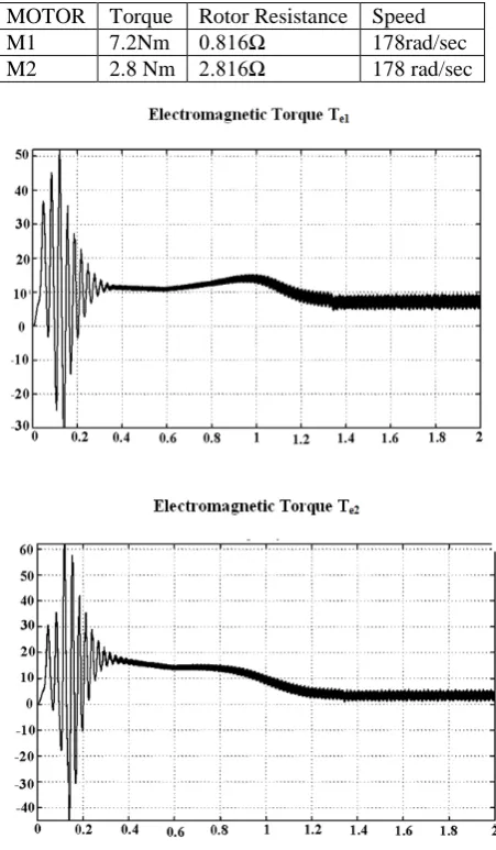
Variation of rotor resistance is considered here as the torque developed by the induction motor is most dependent on the rotor resistance. The simulation results using existing load sharing scheme for un-identical motors is shown in Fig. 3 and is tabulated in Table 2. Though the motors are of same power rating, it is found from Fig. 3 that the motor with lower rotor resistance develops higher torque than the motor with the higher rotor resistance.
Table 2: Torque developed by M1 and M2 with different rotor resistances using existing load sharing scheme
MOTOR Torque Rotor Resistance Speed
M1 7.2Nm 0.816Ω 178rad/sec
M2 2.8 Nm 2.816Ω 178 rad/sec
Fig. 3 Load sharing between two induction motors M1 and M2 with variation in rotor resistance using existing load sharing scheme
From the tabulated results it can be inferred that
467
scheme of load sharing, which determines thedeveloped torque based on the torque speed characteristics of the induction motor.
M1 is overloaded and M2is underutilised due to variation in machine parameters.
In order to compensate for the changes in the motor parameter, the speed command signal to the second motor should be changed accordingly.
To achieve this, the speed command to the second motor should be fed through a command speed compensator. The design of command speed compensator is discussed in the following section.
3. Design of command speed compensator
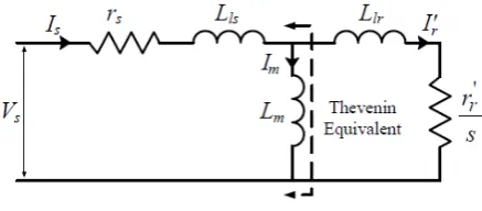
The steady state equivalent circuit of an induction motor[4] is shown in Fig. 4
Fig 4. Steady state equivalent circuit of induction motor
For V/f control of induction motor, the relationship between voltage and frequency[5] is expressed as follows
𝑉𝑟 𝜔𝑟𝑎𝑡𝑒𝑑 =
𝑉𝑠
𝜔𝑒∗ (1)
𝑉𝑠 = �𝜔𝑟𝑎𝑡𝑒𝑑𝑉𝑟 � 𝜔𝑒∗ (2)
𝑉𝑟 is the rated voltage
𝜔𝑟𝑎𝑡𝑒𝑑 is the rated electrical frequency
𝜔𝑒∗ is the commanded electrical frequency
The steady state electromagnetic torque developed by induction motor is given as [4]
𝑇𝑒= 3𝑃2𝑉𝑡ℎ 2
𝜔𝑒 ×
𝑟𝑟, 𝑠 �𝑅𝑡ℎ+ 𝑟𝑟
, 𝑠 �
2
+ �𝑋𝑡ℎ+ 𝑋𝑙𝑟, �2
(3)
where 𝑉𝑡ℎ, 𝑅𝑡ℎ and 𝑋𝑡ℎ can be determined from steady state equivalent circuit of induction motor.
𝑉𝑡ℎ=[𝑟 𝑉𝑠× 𝑗𝑋𝑚
𝑠+ 𝑗(𝑋𝑙𝑠+ 𝑋𝑚)] (4)
𝑅𝑡ℎ =(𝑋𝑙𝑠𝑟𝑠𝑋𝑚+ 𝑋𝑚) (5)
𝑋𝑡ℎ=(𝑋𝑙𝑠𝑋𝑙𝑠+ 𝑋𝑚𝑋𝑚 ) (6)
Since the slip in the motoring region is very low, the above electromagnetic torque equation can be approximated as
𝑇𝑒= 3𝑃2𝑉𝑡ℎ 2
𝜔𝑒×
𝑟𝑟, 𝑠 �𝑟𝑟, 𝑠 �
2 (7)
𝑇𝑒= 3𝑃2𝑉𝑡ℎ 2
𝜔𝑒×
𝑠
𝑟𝑟, (8)
The electromagnetic torque developed by M1 and M2 is indicated using 𝑇𝑒1 and 𝑇𝑒2 respectively. The suffixes 1 and 2 are being used for parameters of M1 and M2 respectively
𝑇𝑒1= 3𝑃2𝑉𝑡ℎ1 2
𝜔𝑒1×
𝑠
𝑟𝑟1, (9)
𝑇𝑒2= 3𝑃2𝑉𝑡ℎ2 2
𝜔𝑒2×
𝑠
𝑟𝑟2, (10)
For equal load sharing
𝑇𝑒1= 𝑇𝑒2
Using Eq (2), (4), (5) and (6) we can obtain an expression for the command speed of the second drive as follows
ωe2= �(ωe1-ωr) �XM1XM2�2�rr2rr1�2�XM1+Xls1XM2+Xls2�2� +ωr (11)
The speed command compensator for the second drive can be designed using the Eq (11).
4. Load sharing using Improved V/f scheme
with command speed compensator
468
formed using Eq(11). The first motor drive system isunchanged whereas the drive for the second motor is modified. The PI speed controller that generates the voltage and frequency control signals to the pulse generator is eliminated. The command speed to the second drive is fed through the speed compensator block. The actual speed of the second motor is taken as a feedback signal to the command speed compensator block. The compensator varies the command speed to the second drive as per the variation in the rotor resistance of the machine
Fig 5. Block diagram for load sharing using proposed modified V/f scheme with a command speed compensator
In order to analyse the effect of the proposed modified V/f scheme using a command speed compensator on load sharing, two un-identical induction motors sharing a common mechanical load of 10Nm at a speed of 1700rpm is simulated using MATLAB/SIMULINK. The two motors are assumed to have
same power rating of 3HP, 220V, 60Hz
different values of rotor resistance. Rotor resistance 𝑟𝑟, of M1 is 0.816Ω and M2 is 2.816Ω
The simulation results obtained after employing the command speed compensator using MATLAB/SIMULINK is shown in fig 6. The torque developed by the motors are tabulated in Table 4. It can be inferred form Fig 6 that load sharing among the motors have improved
Table: 4 Torque developed by M1 and M2 with different rotor resistances using proposed modified V/f scheme with command speed compensator
MOTOR Torque Rotor Resistance Speed
M1 5.2 Nm 0.816Ω 178 rad/sec
M2 4.8 Nm 2.816Ω 178 rad/sec
The voltage and frequncy control signals fed to the pulse generator of the drives of the two motors for achieving this load sharing using command speed compensator is as follows:
M1: 𝑉 = 219 𝑉; 𝑓 = 59.7 𝐻𝑧; 𝑉
𝑓= 3.66
M2: 𝑉 = 206.5 𝑉; 𝑓 = 56.4 𝐻𝑧; 𝑉
𝑓= 3.66
Fig. 6 Load sharing between two induction motors M1 and M2 with variation in rotor resistance employing proposed modified V/f scheme with command speed compensator
5. Conclusions
469
second drive is varied in accordance with the variationin machine parameters. The existing V/f speed control scheme wass modified by including a command speed compensator for the second drive. The simulation of the proposed scheme shows that symmetrical load sharing can be obtained with two induction motors of varying parameters sharing a common load. Also it is found that both the motors are running at a speed of 178rad/sec(1700rpm). Comparison of load sharing between two motors with same power rating and different rotor resistances for conventional scheme and the proposed scheme is shown in Table 5.
Table: 5 Comparison between the developed torques by M1 and M2 using conventional scheme and proposed scheme
Load sharing using existing scheme
M1 M2
Rotor resistance
0.816Ω 2.816Ω
Torque 7.2Nm 2.8Nm Load sharing using
the proposed scheme
Rotor resistance
0.816Ω 2.816Ω
Torque 5.2Nm 4.8Nm
With the inclusion of command speed compensator the torque contributed by the first motor M1 running at a speed of 178 rad/secs (1700rpm) is reduced to 5.2Nm from 7.2Nm. The deviation in the torque contribution by M1 is reduced as shown in Table 6
Table: 6 Comparison of M1 performance before and after inclusion of command speed compensator
Required Torque 5 Nm Torque Without Compensator 7.2 Nm Torque With Compensator 5.2 Nm % Deviation
without Compensator
44
% Deviation with Compensator
4
Inference With the inclusion of command speed compensator the the torque contribution of the M2 has reduced.
With the inclusion of command speed compensator the torque contributed by the second motor M2 running at a speed of 178rad/sec (1700rpm) is increased to 4.8Nm from 2.8Nm. The deviation in the torque contribution by M2 is reduced as shown in Table 7
Table: 7 Comparison of M1 performance before and after inclusion of command speed compensator
Required Torque 5 Nm Torque Without Compensator 2.8Nm Torque With Compensator 4.8 Nm % Deviation without Compensator -78.5
% Deviation with Compensator
-4.16
Inference With the inclusion of command speed compensator the the torque contribution of M2 has increased.
This method can also be extended to obtain proportionate load sharing when induction motors of different power ratings are used.
References
[1] Ivan G. Odnokopylov, Yuri N. Dementev, Ivan V. Usachev, Danil Yu. Lyapunov, Alexander S. Petrusev, "Load balancing of two-motor asynchronous electric drive," International Siberian Conference on Control and Communications (SIBCON), 2015
[2] Jaishanker Iyer, Mehrdad Chapariha, Francis Therrien and Juri Jatskevich, “Improved Torque Sharing in Multi-Induction Motor VFD Systems Using Current Feedback", 25th IEEE Canadian Conference on Electrical and Computer Engineering (CCE CE), 2012, pages 1-5
[3] J. Iyer, K. Tabarraee, S. Chiniforoosh, J. Jatskevich, “An improved V/F control scheme for symmetric load sharing of multi-machine induction motor drives,” presented at the 24th Canadian Conference on Electrical and Computer Engineering, Niagara Falls, Ontario, Canada, 2011, pages 001487-001490
[4] P C Sen, "Principles of Electric Machines and Power Electronics", 2nd edition, John Wiley and sons, 1997
[5] P. C. Krause, O. Wasynczuk, and S. D. Sudhoff, Analysis of electric machinery and drive systems, 2nd ed.: John Wiley & Sons Inc., 2002.
470
published in Power Electronics, Drive Systems andTechnologies Conference (PEDSTC), 2013, pages 1-6 [7] Atalay A.K., Kocabas D. A, Imeryuz M, Gulbache M. O, “Analysis of problems in a load system driven by multiple tandem induction motors", published in MECHATRONIKA, 2012 15th International Symposium, pages 1-5.
Roopa Nayak obtained her B.E degree in Electrical and Electronics Engineering in 2003 and M.Tech in VLSI Design and Embedded Systems in 2007. She has a teaching experience of 10 years and is currently working as an Assistant Professor in Department of Electrical and Electronics Engineering at RNSIT, Bangalore. She is also pursuing part time Ph.D under VTU at EIE department research centre, RNSIT.