109 |
P a g e
DESIGN AND VERIFICATION OF ROBUST ROUTER
FOR SYSTEM ON CHIP APPLICATIONS
M.Pavitra
1, Ch.Sujith Kumar
21
Associate Professor,
2PG Scholar, M.Tech(DSCE), ECE Department,
PBR VITS, KAVALI, (India)
ABSTRACT
Through this paper the attempt is to give a onetime networking solution by the means of merging the VLSI field with the networking field. As now a days the router is the key player in networking domain. So the focus remains on that itself to get a good control over the network, Networking router today are with minimum pins and to enhance the network. By going for the bridging loops which effect the latency and security concerns. The other is of multiple protocols being used in the industry today. Through this paper the attempt is to overcome the security and latency issues with protocol switching technique embedded in the router engine itself. This paper is based on the hardware coding which will give a great impact on the latency issue as the hardware itself will be designed according to the need. In this paper the attempt is to provide a multipurpose networking router by means of Verilog code, by this one can maintain the same switching speed with more secured way of approach have even the packet storage buffer on chip being generated by code in our design in the so we this can also be as the self-independent router called as the VLSI Based router. This paper has the main focus on the implementation of hardware IP router. The approach here is that router will process multiple incoming IP packets with different versions of protocols simultaneously and even it is going to hold true for the IPv4 as well as for IPv6. With the approach of increasing switching speed of a routing per packet for both the current trend protocols. This paper thus is going to be a revolutionary enhancement in the domain of networking.
Keywords: Bridging Loops, IP Packets, Latency, Protocols, Router.
I INTRODUCTION
110 |
P a g e
packets we want to add to our router to route, with this paper of hardware code our approach is to get the basic packets routing with multiple protocols starting with the IPv4 and IPv6.II LITERATURE SURVEY
In this we are comparing the existing generic router architecture and our new robust router architecture. This will give the difference in the designing and would reflect our paper enhancements that we are upgrading in our robust router paper.
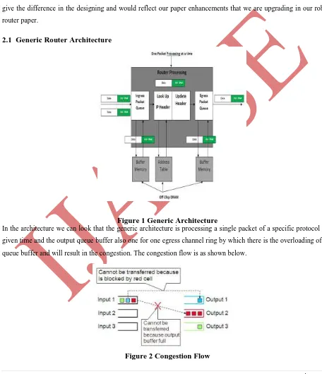
2.1 Generic Router Architecture
Figure 1 Generic Architecture
In the architecture we can look that the generic architecture is processing a single packet of a specific protocol at a given time and the output queue buffer also one for one egress channel ring by which there is the overloading of the queue buffer and will result in the congestion. The congestion flow is as shown below.
111 |
P a g e
III A NEW ROBUST ROUTER ARCHITECTURE
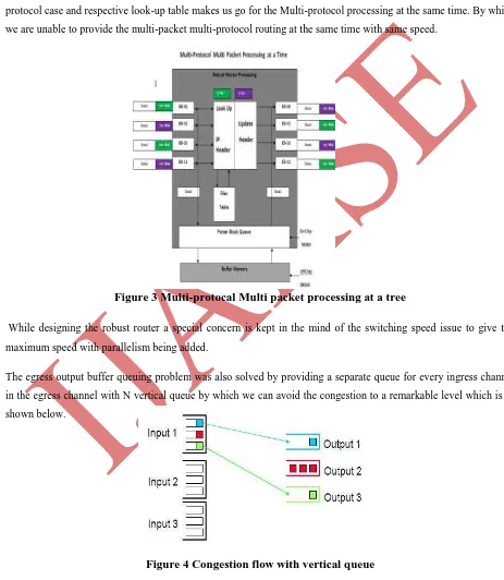
The architecture of robust router is totally based on the Verilog code which would enable our design in the implementation of parallel packet processing for N number of channels. This intern enables the multi packet processing at the same time. With the Verilog code being the base of design we have an option for the addition of protocol case and respective look-up table makes us go for the Multi-protocol processing at the same time. By which we are unable to provide the multi-packet multi-protocol routing at the same time with same speed.
Figure 3 Multi-protocal Multi packet processing at a tree
While designing the robust router a special concern is kept in the mind of the switching speed issue to give the maximum speed with parallelism being added.
The egress output buffer queuing problem was also solved by providing a separate queue for every ingress channel in the egress channel with N vertical queue by which we can avoid the congestion to a remarkable level which is as shown below.
112 |
P a g e
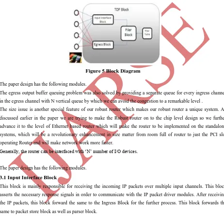
The size issue is another special feature of our robust router which makes our robust router a unique system. As discussed earlier in the paper we are trying to make the Robust router on to the chip level design so we further advance it to the level of Ethernet based router which will make the router to be implemented on the standalone systems, which will be a revolutionary enhancement in size matter from room full of router to just the PCI slot operating Router and will make network work more faster. It looks something like this below.Figure 5 Block Diagram
The paper design has the following modules.
The egress output buffer queuing problem was also solved by providing a separate queue for every ingress channel in the egress channel with N vertical queue by which we can avoid the congestion to a remarkable level .
The size issue is another special feature of our robust router which makes our robust router a unique system. As discussed earlier in the paper we are trying to make the Robust router on to the chip level design so we further advance it to the level of Ethernet based router which will make the router to be implemented on the standalone systems, which will be a revolutionary enhancement in size matter from room full of router to just the PCI slot operating Router and will make network work more faster.
Generally, the router can be interfaced with „N‟ number of I/O devices.
The paper design has the following modules.
3.1 Input Interface Block
This block is mainly responsible for receiving the incoming IP packets over multiple input channels. This block asserts the necessary response signals in order to communicate with the IP packet driver modules. After receiving the IP packets, this block forward the same to the Ingress Block for the further process. This block forwards the same to packet store block as well as parser block.
3.2 Packet Store Block
113 |
P a g e
3.3 Parser Block
This block is mainly responsible for parsing the complete packet into multiple set of data according to its field. The parsed contents will be inputted to the filer block.The above three blocks are merged all together as IIB in code to single file. block initiates the communication with packet store block to fetch the packet to be forwarded. Then, the fetched IP packet will be forwarded to the output interface block with the output channel details, over which the packet has to be transmitted.
3.4 Filer Block
This block is responsible for selecting the egress ring. The block receives the parsed data from the parser block. The parsed data will be forwarded to the filer table. In response to this, the filer table provides the output ring number. Then, the received output from the filer table will be forwarded to the egress block.
3.5 Filer Table
It is a user configurable table. This table contains a set of data in its each slot, against which the data sent by the filer block will be compared. If the filer block inputted data matches with the data of any slot of filer table, then that slot‟s data will be used as egress ring through which received packet will be forwarded.
3.6 Egress Block
This block receives the data from filer block as egress ring number through which the received packet shall be forwarded. Upon receiving the egress ring number, this
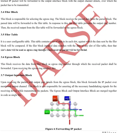
3.7 Output Interface Block
Upon receiving the packet with output port details from the egress block, this block forwards the IP packet over mentioned output channel. This block is also responsible for asserting all the necessary handshaking signals for the receiving device while transmitting the packets. The Egress Block and Output Interface Block are merged together in code as single file.
114 |
P a g e
IV SYSTEM FLOW DIAGRAM
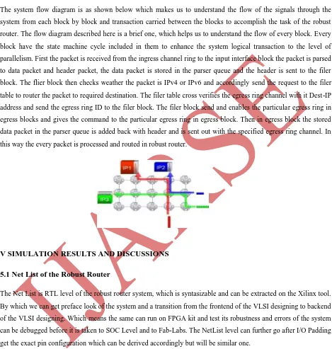
The system flow diagram is as shown below which makes us to understand the flow of the signals through the system from each block by block and transaction carried between the blocks to accomplish the task of the robust router. The flow diagram described here is a brief one, which helps us to understand the flow of every block. Every block have the state machine cycle included in them to enhance the system logical transaction to the level of parallelism. First the packet is received from the ingress channel ring to the input interface block the packet is parsed to data packet and header packet, the data packet is stored in the parser queue and the header is sent to the filer block. The flier block then checks weather the packet is IPv4 or IPv6 and accordingly send the request to the filer table to router the packet to required destination. The filer table cross verifies the egress ring channel with it Dest-IP address and send the egress ring ID to the filer block. The filer block send and enables the particular egress ring in egress blocks and gives the command to the particular egress ring in egress block. Then in egress block the stored data packet in the parser queue is added back with header and is sent out with the specified egress ring channel. In this way the every packet is processed and routed in robust router.
V SIMULATION RESULTS AND DISCUSSIONS
5.1 Net List of the Robust Router
The Net List is RTL level of the robust router system, which is syntasizable and can be extracted on the Xilinx tool. By which we can get preface look of the system and a transition from the frontend of the VLSI designing to backend of the VLSI designing. Which means the same can run on FPGA kit and test its robustness and errors of the system can be debugged before it is taken to SOC Level and to Fab-Labs. The NetList level can further go after I/O Padding get the exact pin configuration which can be derived accordingly but will be similar one.
5.2 SOC Designing
115 |
P a g e
system will have gate delay, propagation delay and wire delays included in them. These are all calculated and made into an optimization level. Then the design is fixed into LUT‟S and the mapped between the LUT‟S further the placement of the LUT‟S are prissily done keeping mind the power utilization and the delay calculated earlier. Then the routing is done between the CLB‟S. Further the bit-stream is generated to test the system and verification doneacross the Net List output to get the exact design. Then the system design is masked and made to the GDSSI Level further to be sent on to the Fab-Labs for fabrication.
5.3 Design Under Test
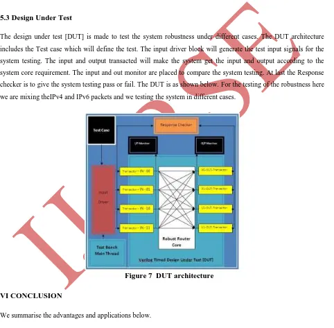
The design under test [DUT] is made to test the system robustness under different cases. The DUT architecture includes the Test case which will define the test. The input driver block will generate the test input signals for the system testing. The input and output transacted will make the system get the input and output according to the system core requirement. The input and out monitor are placed to compare the system testing. At last the Response checker is to give the system testing pass or fail. The DUT is as shown below. For the testing of the robustness here we are mixing theIPv4 and IPv6 packets and we testing the system in different cases.
Figure 7 DUT architecture
VI CONCLUSION
We summarise the advantages and applications below.
6.1 Advantages
116 |
P a g e
Router hardware code is variable High switching speed with any no. of I\o pin connection More secured
Robust router can handle all type of packets (Implemented on IPv4 and IPv6)
6.2 Application
Can be used as public internetworking router Can be used as corporate router
Software company private router (client to client, developer to client) Router for networking research
In other words one point networking solution
6.3 System Test Analysis
Number of gates :- 59855 Total Run time:- 9.018 ns Switching speed:- 662.5 Tbps System Frequency:- 0.11 GHz
Can be fabricated:- by 45 nano technology with Cadence Encounter tool( cost 12000$)
In this paper the code given in the output for IPv4 and IPv6 packets is put in the router at the same time. The Robust Router will route both packets at the same time at the same speed. The Robustness is simulated with Model-Sim Tool with different Test Cases and the same code‟s NetList is extracted with Xilinx Tool for the synthesizable code. The same can be taken to the SOC (System on chip) level with Cadences Encounter Tool.
The same Verilog code design can be taken to the implementation of MPLS (Multi-Protocol Label
Switching).
The some code design can be taken to the SOC (System on chip) level and can be implemented as the
Ethernet Standalone System Router.
The same code can be made variable with TCP and UDP Protocols.
REFERENCES
117 |
P a g e
[2] Y. Rekhter, B. Davie, D. Katz, E. Rosen, and G. Swallow, “Cisco Systems‟ Tag Switching ArchitectureOverview,” IETF RFC 2105, Feb. 1997. Amir.Palnitkar. 2nd Edition
[3] J. Moy, OSPF: Anatomy of an Internet Routing Protocol, 1998
[4] Tobias Bjerregaard and Shankar Mahadevan. A survey of research and practices of network-on-chip. ACM Comput. Surv., 38(1):1, 2006.
[5] Charles.H.Roth,Jr Digital System Design Using VHDL [6] Jenkins,jesse H.Designing with FPGAs and CPLDs
[7] Abromovici,M,Breuer Digital System Testing and Testable Design.