Journal of Physics: Conference Series
PAPER • OPEN ACCESS
Computer-aided electron-beam deflection control system
To cite this article: E Koleva et al 2020 J. Phys.: Conf. Ser. 1492 012013View the article online for updates and enhancements.
21st International Summer School on Vacuum, Electron and Ion Technologies Journal of Physics: Conference Series 1492 (2020) 012013
IOP Publishing doi:10.1088/1742-6596/1492/1/012013
Computer-aided electron-beam deflection control system
E Koleva1,2,3,5, L Koleva2, G Mladenov1,3, D Trushnikov4 and A Andonov2
1Acad. E. Djakov Institute of Electronics, Bulgarian Academy of Sciences,
72 Tzarigradsko Chaussee, 1784 Sofia, Bulgaria
2University of Chemical Technology and Metallurgy,
8 Kliment Ohridski Blvd., 1756 Sofia, Bulgaria
3Technological Center on Electron Beam and Plasma Technologies and Techniques,
TC EPTT Ltd., Bulgaria
4Perm National Research Polytechnic University,
29 Komsomolsky Prospekt, 614000 Perm, Russian Federation e-mail: [email protected]
Abstract. The electron beam processes – 3D selective melting (3D printing), welding, etc. are complex processes with many processing variables, which require integration of interfaces for control of the processes on different levels through hierarchical equipment models, functional data and operation control models. We developed a user interface software application for controlling the electron-beam motion along several types of trajectories and a free complex shape trajectory by controlling the deflection system parameters. Several types of motion patterns with different velocities are realized, together with the possibility of choosing a free trajectory by defining the electron-beam path by a graphical image.
1. Introduction
The electron-beam (EB) processes – 3D selective melting (3D printing), welding, melting and refining, evaporation, surface modification, etc. are complex processes with many processing variables, which require integration of the process control interfaces on different levels through hierarchical equipment models, functional data and operation control models. Many EB processes, especially the selective melting for the development of 3D structures, need very precise management and control of the EB parameters. The choice of EB processing parameters generally depends on the specific process, the properties of the treated materials and the EB equipment available. The existing process controls of EB equipment are typically aimed at controlling the basic machine settings, such as accelerating voltage, EB current, focusing coil current, vacuum level, EB velocity, working distance, etc. There exist methods of EB focus control and monitoring in EB welding based on registering the secondary emissions from the welding area [1]. The relation used between the secondary emissions and the focusing lens current has an extremum, so that this relation specifically has a dead zone and two values of the focusing lens current providing the same value of the secondary-current signal parameters. Therefore, adaptive systems of EB focus stabilization of this kind use low-frequency scanning, which substantially limits the working speed of these systems. The focus position is extremely important for EB welding and affects the quality and geometry of the welded joints produced [2, 3]. An overview of
21st International Summer School on Vacuum, Electron and Ion Technologies Journal of Physics: Conference Series 1492 (2020) 012013
IOP Publishing doi:10.1088/1742-6596/1492/1/012013
2
different focus-control methods is presented in [4]. In [5], a direct fuzzy controller is presented for an EB focusing system. A device for determining the energy density distribution and for EB focus control was also developed [6].
The beam profile is monitored by the enhanced modified Faraday cup (EMFC) diagnostic tool proposed by J. Elmer and co-workers [7, 8]. The benefit of integrating this diagnostic tool into future process-control regimes is that the beam radial current distribution characteristics, as the peak power density, full width at half-maximum and the full width at 1/e2 value, can be quantified. The results
show that machine performance, in terms of these measured beam characteristics, varies over time. The emittance is a characteristic of the beam quality that determines the non-laminarity of the particle trajectories in the beam; it is chosen as a suitable parameter for standardizing the electron optical technology systems. Evaluating this parameter is a precondition for achieving good quality, repeatability and reproducible characteristics of EB welds. This parameter forms the basis of transferring a concrete technology from one machine to another, thus minimizing the volume of preliminary experimental tests aimed at achieving satisfactory regime parameters. In [9-11], some methods are analyzed of intense beam emittance evaluation and a new method is proposed for emittance determination utilizing three beam-profile measurements along the beam axis. Another method was also developed using the changes of the beam focusing current during the beam-profiles measurement utilizing a non-movable modified Faraday cup.
In [5, 12], stationary and dynamic models for the deflection distance are considered for EB deflection control in the case of known electric and magnetic field distributions. In [4], a study is presented on the behavior of the current in the plasma formed in the EB operation area. This approach can be used to obtain the amplitude and the phase ratios, as well as to determine the signals dependence of the current in the plasma on the deflecting coil signals during EB welding processes.
In this paper, the development is presented of an EB software control system aimed at integrating the EB equipment and the process management. EB deflection system management software is developed to generate control signals for the EB installation. It gives the possibility to simulate and control the EB motion along different trajectories at different velocities. Special attention is paid on the free EB trajectories option and the possibility to generate such trajectories using images of real objects. The deflection control in this case is based on estimating the control deflection signals implementing the estimated (x, y) coordinates. The generated image-based scaled coordinates can also be used for x0y (two-dimensional) manipulator motion control [13]. The estimated performance and control models and algorithms should be validated experimentally.
2. Electron-beam software control system
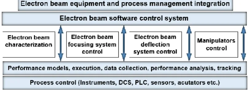
The EB software control system under development involves several related directions: EB characterization; management of the focusing and deflection systems; management and control of the manipulators (figure 1). It is part of the total EB equipment and process management integration, involving the development of an engineering support system and incorporating data collection and acquisition (DCA), information analysis (IA), decision support system (DSS) and system management (SM) [14, 15].
21st International Summer School on Vacuum, Electron and Ion Technologies Journal of Physics: Conference Series 1492 (2020) 012013
IOP Publishing doi:10.1088/1742-6596/1492/1/012013
The distributed control systems (DCS), programmable logic controllers (PLC), sensors, actuators, etc. ensure the process data acquisition and control through performance models for the process, equipment, materials and controllers.
3. Deflection system control
The EB motion along different paths is determined by the magnetic field formed by the deflection system depending on the process performed and the shape and location of the samples treated. The place of interaction of the electron beam with the material can be controlled by beam deflection or/and by moving the processed samples by a two- (or three-) dimensional CNC manipulator. In [5], it is found that in the cases of rectangular and acute-angle corners, the implementation of a manipulator should be combined with a deflection system control. There usually exist design limitations for the maximum deflection angle of each electron gun. These, together with the dimensions of the vacuum chamber and the distance from the magnetic lens of the gun, define the maximum deflection distance from the axial base beam position. The EB deviation in two mutually perpendicular directions at angles to about 7 ‒ 10 degrees is performed by means of two pairs of deflection coils (figure 2) [12, 16]. The deflection distance on the axes Ox and Oy depending on the deflection coil currents Idefl,x
and Idefl,y at a constant value of the acceleration voltage Ua[5, 16] can be written as: 𝑥𝑑𝑒𝑓𝑙 = 𝐶𝑑𝐼𝑑𝑒𝑓𝑙,𝑥⁄√𝑈𝑎and𝑦𝑑𝑒𝑓𝑙 = 𝐶𝑑𝐼𝑑𝑒𝑓𝑙,𝑦⁄√𝑈𝑎 ,
where C is a constant depending on the electron charge and stationary mass, the vacuum permittivity, and the deflection coil configuration parameters; d is the distance between the top of the vacuum chamber and the surface of the processed material (the exact position of the deflection coils cannot be estimated).
Figure 2. Deflection coils and signals.
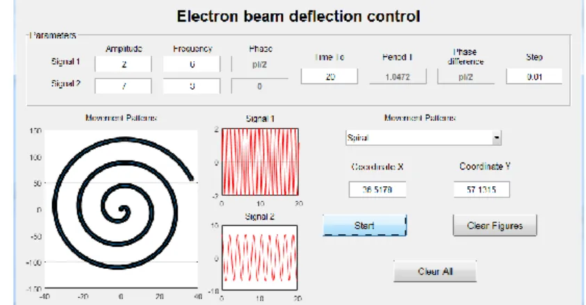
Figure 3. Electron-beam control software system – deflection
control.
The deflection voltages Udefl (Idefl currents) applied to the two pairs of deflection coils (signal 1 and
signal 2 on figure 2) are:
Udefl,x(t) = A(t)*sin[x(t)*t+x(t)], and Udefl,y(t) = B(t)*sin(y(t)*t + y(t)),
where A and B are the amplitudes, are the oscillations frequencies, and the phase difference
t y
t x
t is defined by the phases of the two signals. The amplitudes, frequencies and phase differences of the two signals may be constant or may vary over time in a particular pattern. The period T (the time needed for one full turn of the electron beam) at a constant frequency value is T = 2/; if the working time is T0, the number of turns is T0/T.
Figure 3 presents the module of the EB control software system for deflection control. Several types of motion patterns with different velocities are realized: line; several lines at different angles,
21st International Summer School on Vacuum, Electron and Ion Technologies Journal of Physics: Conference Series 1492 (2020) 012013
IOP Publishing doi:10.1088/1742-6596/1492/1/012013
4
circle, ellipse spiral, spiral (ellipse), Lissajous figures, etc. The parameters for Signal 1 and Signal 2 can be set by the user. The current coordinates of the overall effect of the two signals can be observed as values and a graph. The example shown in figure 3 represents a spiral with amplitude of 2 for Signal 1 and 7 for Signal 2; a frequency ratio of 6/3; a phase difference δ = π/2; a working time To = 20 s increasing at a step s = 0.01; and a period T = 1.05 Hz.
4. Free electron-beam trajectory
The option of free EB trajectories gives the possibility to generate trajectories based on images of real objects (or software generated 3D model structures). The deflection control in this case is based on estimating the deflection control signals that will implement the estimated (x, y) coordinates. The first stage is to estimate the coordinates of the desired EB path connected with the real object. There are two possible patterns, namely, scanning or outlines (or combined). Figure 4 presents an example of an outlined EB trajectory. From the original greyscale image, a binary image is obtained and the outlines’ coordinates of the object are estimated after scaling to real object dimensions.
Figure 5 presents the desired EB trajectories for multiple objects. The image needs rescaling before the true object coordinates are obtained.
Figure 4. Original greyscale image, binary image
obtained of the object outlines, and desired EB trajectory of motion (unscaled).
Figure 5. EB trajectories of motion (unscaled) for multiple objects.
a) b) c) d)
Figure 6. Calculated values of Signal 1 (a) and Signal 2 (b) for managing the voltage of the two
pairs of deflection coils; two trajectory patterns ‘outlines’ (c) resulting from Signal 1 and Signal 2; and ‘scanning’ trajectory pattern (d).
The second step is transforming the coordinates into signals for the deflection coils. Figure 6 shows the calculated values of Signal 1 and Signal 2 and their combined effect of managing the voltage of the two pairs of deflection coils (scaling is not performed). The image-based coordinates generated can also be used for direct x0y (two-dimensional) CNC manipulator motion control.
21st International Summer School on Vacuum, Electron and Ion Technologies Journal of Physics: Conference Series 1492 (2020) 012013
IOP Publishing doi:10.1088/1742-6596/1492/1/012013
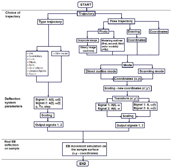
Figure 7. Schematic diagram of the electron-beam deflection control system.
Figure 7 is a generalized schematic diagram of the electron-beam deflection control system. Initially, the choice should be made of the electron-beam motion trajectory between the type of motion pattern or a free-trajectory motion. Additional types of trajectories can be defined by a user defined model (flower, etc.). The free-trajectory motion pattern can be provided by a photograph, by a drawing produced by 2D design software, or directly by inserting the object outline coordinates. In the cases of starting with a photograph, the 2D outline coordinates can be obtained either by processing the image into greyscale and binary image, or by also by model estimation of different parts of the outlines of the object with first-, second- and third-order equations of the type:
𝑦̂ = 𝑏0+ ∑𝑘 𝑏𝑖𝑓𝑖(𝑥)
𝑖=1 ,
where bi are estimated polynomial equation coefficients, 𝑓𝑖(𝑥) are the functions of the coordinate x (x, x2 and/or x3), depending on the order k of the polynomial model. Then, once the work mode is selected
– direct outline mode or scanning mode, the center of the coordinate system is moved to the center of the object (figure 6 c) and new coordinates are evaluated. The next step involves the transformation of the new coordinates obtained into control signals defined either by a constant amplitude and varying frequency or by varying amplitude and constant frequency. The combined effect of the two signals and the deflection of the electron beam (x, y coordinates) will be the same in both cases.
21st International Summer School on Vacuum, Electron and Ion Technologies Journal of Physics: Conference Series 1492 (2020) 012013
IOP Publishing doi:10.1088/1742-6596/1492/1/012013
6
5. Experimental measurements
We verified experimentally the parameters of the EB equipment (figure 8) (figure 9), namely, the parameters of the EB installation deflection system, the electron beam, the electron gun and the vacuum chamber. Experiments were performed to validate the model estimates concerning the correspondence between the process parameters and the exact EB positioning (needed for scaling the coordinates).
Figure 10 presents the measured values of the voltages of Signal 1 and Signal 2 (phase difference is
/2) for the deflection coils and the resulting real EB trajectory.
Figure 8. Electron-beam installation with power
2 kW, pressure 710-3 Pa.
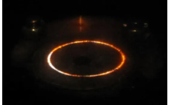
Figure 9. Circle trajectory mode of the electron
beam in the vacuum chamber.
Figure 10. Measured values of the voltages of Signal 1 and Signal 2 (phase difference /2)
for the deflection coils and the resulting electron-beam trajectory. 6. Conclusions
EB deflection system management software is developed to generate control signals for an EB installation. It allows one to simulate and control the EB motion along various trajectories at various velocities. The free EB trajectories option offers the possibility to generate trajectories baseа on images of real objects. The generated image-based scaled coordinates can also be used to control x0y (two- dimensional) manipulator motion. In order to realize the management, the estimated performance and control (PID, adaptive, neural, fuzzy etc.) models and algorithms should be validated experimentally. The beam pattern used in each case depends of the process (3D selective melting, welding, melting, etc.) and the shape of the concrete sample.
Acknowledgements
The work has been supported by the Bulgarian National Scientific Fund under contract KP-06-N27/18 and Russian Foundation for Basic Research RFBR №18-08-01016 А as well as by the Ministry of Education of Perm Region (S-26/787 from 21.12.2017).
21st International Summer School on Vacuum, Electron and Ion Technologies Journal of Physics: Conference Series 1492 (2020) 012013
IOP Publishing doi:10.1088/1742-6596/1492/1/012013
References
[1] Mauer K 1976 Patent No119363/20.04.1976 (Germany) [2] Koleva E 2001 Vacuum62/2-3 151-7
[3] Koleva E 2005 Vacuum77 413-21
[4] Trushnikov D, Krotova E and Koleva E 2016 J. Sensors 1687725X 16877268
[5] Oltean S-E, David L and Dulău M 2007 Rev. Roum. Sci. Techn. – Électrotechn. et Énerg. 52/1 43–50 (Bucarest)
[6] Belenykiy V, Salomatova E, Krotova E, Olyshanskaya T, Trushnikov D, Musihin N, Koleva E and Lyvovich G 2016 Patent RU 2580266
[7] Elmer J W, Teruya A T and O'Brien D W 1993 Welding J.72/11 493
[8] Elmer J W and Teruya A T 1998 Sci. and Tech. of Welding and Joining3/2 51 [9] Koleva E, Vutova K, Wojcicki S and Mladenov G 2001 Vacuum62/2-3 105–11
[10] Mladenov G and Koleva E 2010 Welding: Processes, Quality and Applications Design of High Brightness Welding Electron Guns and Characterization of Intense Electron Beam Quality (Seria Mechanical Engineering-Theory and Applications) ed Richard J Klein (Nova Sci. Publishers New York) chapter 1 pp 1-99
[11] Koleva E, Menhard C, Loewer T and Mladenov G 2006 Electrotechnica & Electronica 41/5-6 51-60
[12] Mladenov G 2009 Electron and Ion Technologies (Publ. Prof. Marin Drinov) [13] Burak S 2013 J. Japan Soc. Precision Eng.79/7 631-8
[14] Koleva E, Dzharov V, Kardjiev M and Mladenov G 2016 J. Phys.: Conf. Series700 012012 [15] Koleva L, Koleva E, Batchkova I and Mladenov G 2018 J. Phys.: Conf. Series992 012014 [16] Koleva E, Dzharov V, Gerasimov V, Tsvetkov K and Mladenov G 2018 J. Phys.: Conf. Series