Sharif University of Technology
Scientia IranicaTransactions B: Mechanical Engineering www.scientiairanica.com
Experimental investigation into shock waves formation
and development process in transonic ow
M. Farahani
and A. Jaberi
Department of Aerospace Engineering, Sharif University of Technology, Tehran, Iran. Received 11 May 2016; received in revised form 12 August 2016; accepted 8 October 2016
KEYWORDS Shock waves formation process; Transonic ow; Shadowgraphy visualization; Splitting of shock waves;
Zeh shock.
Abstract. An extensive experimental investigation was performed to explore the shock waves formation and development process in transonic ow. Shadowgraph visualization technique was employed to provide visual description of the oweld features. Based on the visualization, the formation process was categorized into two intrinsically dierent phases, namely, subsonic and supersonic. The characteristics of subsonic phase are well known; however, those of the supersonic one are far less studied. The supersonic phase itself is made up of two consecutive phases, namely, approaching and sweeping. The eects of each phase on the oweld characteristics and on shaping the supersonic regime were studied in details. In order to generalize the results, three dierent models were tested. A special terminology is suggested by authors to ease the process description and pave a way for future studies. Above all, as the transition from transonic regime to the supersonic one is a vague concept in terms of physical reasoning, a new explanation is proposed that can be used as a criterion for distinguishing between transonic and supersonic regimes. © 2017 Sharif University of Technology. All rights reserved.
1. Introduction
Knowledge of the ow conditions over a body in transonic and supersonic speeds is of great importance in various aspects, particularly the appearance of shock waves. These established shocks have profound eects on the aerodynamic characteristics of a vehicle and, therefore, a detailed investigation is necessary. A principal phenomenon related to shock waves is their formation and development process that takes place within transonic regime. This process has been studied by many research studies; however, there are still many aspects that require further investigation.
Broadly speaking, a shock wave occurs in super-sonic ow because of two reasons: rst, to turn the
*. Corresponding author. Tel.: +98 21 66022731; Fax: +98 21 66022731
E-mail address: [email protected] (M. Farahani) doi: 10.24200/sci.2017.4309
streamlines tangent along the non-penetrating surface or/and, second, to compensate for the pressure dier-ence between upstream and downstream and satisfy pressure boundary conditions. The former is usually seen in external ows and the latter mostly happens in nozzles and diusers. In some supersonic wind tunnels such as the one used here, at rst, the nozzle exit to throat ratio is set; then, during the startup and after the ow reaches sonic conditions at the throat, a primary normal shock appears, which separates supersonic and subsonic regions. In order to reach the determined Mach number at test section by increasing blowing power of wind tunnel engine, the normal shock moves downstream and becomes stronger. In this phase, acceleration of the ow results in the variable strength of the normal shock wave, which is the main source of unsteadiness. On the other hand, in the presence of a model in test section, some shock or expansion waves would be established over it to ensure that the ow remains in the direction of the body surface everywhere. Due to this, the strengths of
dierent circumstances are the main focus of such studies. In contrast, there are only a few works regarding the case when the free-stream ow passes the sound speed. Patz [7] investigated the formation of bow waves around blunt bodies in the ow behind a mowing shock and derived stand-o distances and formation times for various blunt bodies. Davies [8] also experimentally explored the shock waves structure when a primary normal shock passed over a blunt body; further, he suggested a schematic description of the formation process, which was reproduced with very more details in this work.
In this survey, both phases are investigated and organized in details; but, since less attention has been paid to the supersonic phase, an in-depth eort is put to identify its unique characteristics. The process continues until the transonic regime ends and the supersonic regime begins. To authors' knowledge, there is no approved physical explanation to determine this transition, even though Mach number of 1.2, which is strictly a rule of thumb, is usually implemented. In this study, a physical denition is proposed to dierentiate between transonic and supersonic regimes.
To follow the formation and development pro-cesses of shock waves in details, visualization meth-ods seem to be very useful tools. In this research, shadowgraph technique is employed. Shadowgraphy is the most ubiquitous and simplest of all the optical ow diagnostics, which is also the best for imaging shock waves. It reveals shock waves clearly while de-emphasizing other less abrupt ow features [9].
The supersonic phase of shock wave formation and development process is described thoroughly for the model and new phenomena and characteristics are introduced. Obviously, these results cannot be conrmed and generalized if only one case is taken under consideration. For this sake, shadowgraphs of three models are compared. Further, the eect of nose shape on the process is investigated.
Experimental studies are necessary in order to provide \benchmark" data for CFD code validation and, primarily, to understand the uid dynamics of a phenomenon. The present study falls within the latter category. It describes the shock system formation and
has a test section of 60 cm 60 cm 120 cm and is equipped with various internal strain gauge balances, pressure transducers, high-speed camera, shadowgraph system, etc. A detailed description of the wind tunnel can be found in [10].
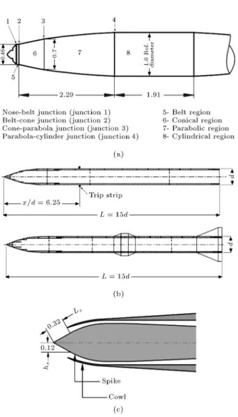
Three models with dierent congurations and dierent nose shapes are provided for tests. The rst model is an axisymmetric body with a blunt nose and a maximum diameter of 64.3 mm. The detailed descrip-tion of the model geometry and its nomenclature is given in Figure 1(a). This geometrical nomenclature is used to ease the interpretation of ow characteristics. The second model, the ogive one, is a long axisym-metric body and has a neness ratio of 2.5 equipped with a circular-arc, ogival nose tangent to a cylindrical after-body with L=d = 15 (Figure 1(b)). Moreover, in order to study the eects of cross section changes on the formation process, a belt with inclination angle of 5 degrees is installed on its cylindrical section. In addition, a guitar wire with a diameter of 0.9 mm is installed at x=d = 6:25 to induce disturbances into the oweld. These two cases are very helpful to survey the supersonic phase of the shock formation process.
The third model, namely, the inlet model, is a supersonic axisymmetric external compression model, as shown in Figure 1(c), of which the main model parts are specied. The main parts include an external cowl that produces ow compression and is connected to an axisymmetric subsonic diuser, consisting of a cowl and a spike. The selection of these models is based on their dierent nose shapes, which mostly aect the char-acteristics of supersonic phase. In eect, blunt nose, sharp nose, and inlet nose models cover nearly all possi-bilities that can happen in the shock formation process. Tests are performed at free-stream Mach numbers ranging from 0.6 to 2.0. For recording the shadow-graphs, a CASIO EX-F1 digital video camera is used, which provides high-speed imaging. It can record 300 frames per second with a resolution of 512 384 pixels and is capable of 1200 fps at further reduced image size. 3. Results and discussion
Figure 1. Schematic of dierent models used (all linear dimensions in calibers): (a) Model A: its geometry, and nomenclature, (b) model B: Ogive model Perturbed wire (up), belt-installed (down), and (c) model C: inlet model.
formation and development process have been catego-rized into two consecutive phases. The rst phase de-picts the formation process when the free-stream Mach number is lower than unity (subsonic phase), while at the second phase it increases to M1 > 1 (supersonic
phase). The second phase has more complexities and, hence, reveals more special behaviors. (Note: subsonic and supersonic phases are just two steps of transonic regime and must not be confused with subsonic and supersonic regimes). In the following, the principal characteristics of the process will be explored via detailed description of the shadowgraphs of model A and, then, the results will be compared with ogive and inlet models.
3.1. Subsonic phase
Figure 2 shows a series of shadowgraphs illustrating the oweld around model A for the subsonic phase of shock formations. This gure consists of 12 steps and
Figure 2. Shadowgraphic visualization of the subsonic phase around model A.
begins with the rst appearance of a shock wave over the model (critical free-stream Mach number) in Step 1 and ends with the rst appearance of the shock in front of the model (supersonic free-stream Mach number) in Step 12.
At the rst step, the ow expansion after the parabola-cylinder junction produces a locally super-sonic ow. This supersuper-sonic ow then becomes subsuper-sonic via a weak normal shock right after junction 4 (as seen in Figure 1). Even though this normal shock is very inconspicuous, its rst advent is constituted as the rst step of shock wave formation process.
At Step 2, new shocks appear at junction 1 and on the conical region. The small normal shock forming after junction 1 is very weak and, according to the shadowgraphs, its strength does not change signi-cantly by increasing the free-stream Mach number. The formed shock on the conical region is placed right in the separated ow, though it does not aect the separation pattern. More importantly, the primary normal shock at junction 4 is shaped like a lambda, which is a well-known characteristic of transonic shock waves. Furthermore, at this step, a trace of a weak shock at the Cone-Parabola junction is seen for the rst time.
Within Steps 3 to 6, by increasing the free-stream Mach number, all the established shock waves get stronger and the transonic characteristics are revealed
on the conical section, that makes it look outwardly with respect to the inow. As the last point, the tiny shock after junction 1 remains almost unchanged within the subsonic phase steps.
From Steps 7 to 9, dierent trends are seen with dierent shocks. For shocks on the cylindrical and parabolic regions (after junctions 3 and 4), the previous trend still goes on. At Step 8, it is completely obvious that the shock on the parabolic section is altered into a lambda one. Further, at this step, the main shock on the cylindrical region is placed exactly on the edge of the test section window and cannot be seen from Step 9 on. In contrast, the strength and extension of the shock on the conical portion decline such that, at Step 9, its size decreases signicantly. Due to the very small size of the shock in junction 1, it is very dicult to follow its variations, although at Step 9, a reduction in its extent is observable.
As the free-stream Mach number approaches unity, the well-known transonic characteristics of the oweld disappear. This process begins at Step 10, when the normal shock on the parabolic region de-creases in extension and strength while gradually re-turning back to its initial position. At this step, the remains of both junctions of shocks 1 and 2 are innitesimal. Unfortunately, the window frame limitation hampers us from following the main shock over model A; however, according to the literature, it nally stands on the trailing edge [5,11]. Finally, at Step 11, there is no trace of the previous shocks at junctions 1 and 2 and the normal shock on the parabolic portion, which has now moved back exactly on junction 3, is miniature. Now, the shock waves formation process is on the verge of its second phase. By disappearance of all the transonic shocks at Step 12 and emergence of a strong normal shock in front of the model, the second phase or the supersonic phase starts. 3.2. Supersonic phase
The ow structure of supersonic phase is much more complex and, since no rigorous research has been conducted to study it, the ow features are mostly un-known and unidentied. To cope with this deciency, the supersonic process is investigated comprehensively
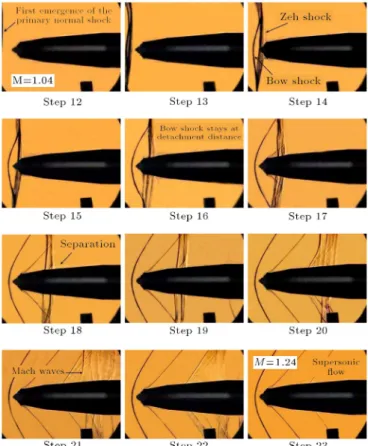
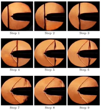
Figure 3. Shadowgraphic visualization of the supersonic phase around model A.
by exploring the shadowgraph results of all three models in details. Furthermore, the authors have designated some patterns and features of the oweld to organize the process and build up a basis for further studies on this subject.
In Figure 3, a chain of shadowgraphs depicts the supersonic phase of the shock waves formation around model A. The photos are labeled from Steps 12 to 23 in order to keep the overall process, from subsonic to supersonic, in a straight line and to avoid any confusion. Clearly, Step 12 is of the same subsonic phase, emphasizing the process continuity. At this step, the sign of a normal shock is evident, even though, due to the frame dimensions, nothing more is identiable. Considering this step as the beginning of the supersonic phase can be illusive. Indeed, the initial position of the primarily formed normal shock when the free-stream Mach number reaches unity can be at a farther distance from the model (theoretically at innity [12]), and by increasing the free-stream Mach number, it approaches the model. In eect, this step is not the rst emergence of the normal shock at supersonic phase, even though the time dierence is negligible.
The shadowgraph Step 13 discloses the unique phenomenon of supersonic phase of shock system formation, i.e. splitting. The division of a stronger shock wave into two or more weaker shocks is titled
\splitting" in this paper. It seems that splitting process happens because the ow should become subsonic and, since the primary shock waves are not strong enough to decelerate the ow, a secondary shock wave forms right behind it. The secondary shock(s) assures deceleration of the ow back into subsonic speed. In this regard, splitting plays a major role in reshaping the oweld structure.
At Step 13, the primary normal shock is split into two adjacent shock waves. These shocks come closer to the model as the free-stream Mach number increases. Both shocks are distorted at their upper ends; this distortion is not an intrinsic trend of the shocks and is allegedly because of some discontinuity on the upper wall of the test section. The convex shape of the farther shock reveals that it is going to establish the supersonic bow shock. The slide of Step 14 depicts this more clearly, where the two adjacent shocks get separated more and more and the establishment of the bow shock is obvious.
A special nomenclature is suggested to describe the unique structure of the shocks. The two adjacent shocks look like a bow and a \Zeh" (Zeh is the exclusive word in Persian literature for the bow string and it is more appropriate to be used here). The convex-shape shock ultimately becomes bow shock, and the straight one is named Zeh shock. The Zeh shock is responsible for forming the nal pattern of shock system over the model. From now on, as the free-stream Mach number increases, the Zeh shock goes through a series of ac-tions, which alter its nature thoroughly. By increasing the free-stream Mach number, the Zeh shock begins to split into weaker shocks while moving downstream. Note that the Zeh shock has a low-amplitude oscillation and splitting happens rapidly; thus, the shadowgraphs around it are not clear enough to distinguish the split shock waves. At the same time, the bow shock reaches its nal position in Step 15 (Figure 3). The interval between the rst emergence of the initial normal shock (the onset of the supersonic phase) and the moment the bow shock stands at its eventual point is designated as the approaching phase.
From Step 16 on, the second phase of supersonic phase, i.e. sweeping phase, begins. As the Zeh shock or its split sweeps the model, the oweld behind it holds the characteristics of the supersonic regime. For instance, at Step 17, by passing the Zeh shock from the Belt-Cone junction, an oblique shock wave emerges right on the junction. A close examination of this shadowgraph points out that, in addition to the oblique shock formation, a weak Mach wave is also formed after the Nose-Belt junction, which seems to coalesce with the oblique shock.
By increasing the free-stream Mach number, the normal shock splits from the primary Zeh shape and moves downstream while splitting into weaker shocks.
The process continues until they are replaced by several Mach waves. The corresponding photos for Steps 20, 21, and 22 in Figure 3 show how the adjacent Mach waves get separated from each other, distribute over the model, and nally disappear gradually. Indeed, at Step 23, there is no sign of the primary Zeh shock, which means that the shock wave formation process is practically nished.
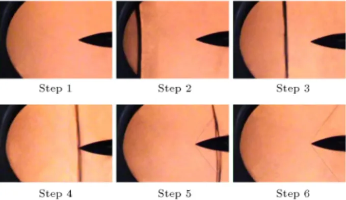
In contrast to the subsonic phase, the supersonic phase is accompanied by severe interaction between shock waves and boundary layer, which inuences ow separation signicantly. The separation variations will be discussed briey. As the Zeh shock reaches the Belt-Cone junction at Steps 14 and 15 (Figure 3), a perceptible increase in the thickness of the separation layer, in comparison with Steps 12 and 13, is observed. At Step 16, as the Zeh shock passes the Belt region, it falls in the middle of separation layer and makes the layer thicker in the region behind the shock by imposing a higher pressure. At Step 17, the Zeh shock splits into several weaker shocks and an oblique shock appears on junction 2; all separation layers ahead and behind the shocks vanish. Note that the ow behind the oblique shock does not separate since it smooths the pressure gradient ahead and behind it. However, as the split shock reaches the parabola region, the ow separates right after the last shock wave. This separation pattern is seen in Steps 18 and 19. Finally, by appearance of Mach waves, within Steps 20 to 23, no extra pressure is imposed on the oweld; hence, the boundary layer remains attached over all sections of the model. 3.3. Shadowgraphs of ogive and inlet models Figure 4 shows six consecutive shadowgraph photos il-lustrating the supersonic phase of the transonic regime around the nose of the ogive model (model B). Since the long cylindrical section of the ogive model is tested with two dierent congurations, its shadowgraphs are discussed separately. At Step 1, the free-stream Mach number reaches near unity and no shock wave is observable within the scope of shadowgraphs. As the
Figure 4. Shadowgraphy photographs of supersonic phase around nose of ogive model, model B.
the rst emergence of the initial normal shock and the moment it touches the nose of the body.
From Step 4 on, the initial normal shock takes the shape of the so-called Zeh shock, since it passes the model nose while settling down the supersonic ow around model. It must be noted that this nomination is not in disagreement with the previous denition of Zeh shock. Indeed, the normal shock that sweeps the model and splits into weaker shock waves is named the Zeh shock in this paper, irrespective of whether the bow is formed or not. The sweeping phase is completely similar to what was described for model A and begins from Step 4 on. As seen, from Step 5, an attached oblique shock is formed on the nose of model and the Zeh shock seems to move downstream as the free-stream Mach number is further increased. Finally, at Step 6, a full supersonic ow is attained around the nose of the ogive model.
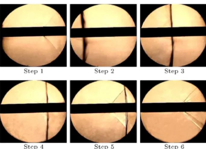
The Zeh shock continues its motion on the cylin-drical section of the ogive model. Figures 5 and 6 depict the supersonic phase on this section for both perturbed wire and belt installed congurations, respectively. At Step 1 of Figure 5, a sign of Zeh shock is observable. In addition, a weak oblique shock is seen to form on the wire, which is formed due to the ow expansion behind the trip strip. At Step 2, the Zeh shock sweeps the long body while reducing the local Mach number of the ow eld. This is clear due to disappearance of the oblique shock seen in Step 1 (Figure 5). At Step 3, the Zeh shock reaches the middle of the cylindrical section of the model; however, it is not split yet. The rst sign of splitting is observed at Step 4, where the Zeh shock has passed the trip strip and a detached oblique shock is established. By increasing the free-stream Mach number, this oblique shock forms in the vicinity of the trip. At this step, i.e. Step 5, the splitting of Zeh shock is clear. Finally, at Step 6, the Zeh shock has swept the body and the characteristics of supersonic regime are settled down. In addition to the detached oblique shock, another shock is formed behind the trip wire, which is clearly due to the expansion wave formed behind the trip strip wire. Note the trip strip wire has a diameter of 0.9 mm and when it is installed on the model at its present location, the local Reynolds
Figure 5. Shadowgraphs of supersonic phase around perturbed cylindrical section of ogive model (with trip strip), model B.
Figure 6. Shadowgraphs of supersonic phase around belt-installed cylindrical section of ogive model, model B.
number over it is equal to 15 106, which is enough to
perturb the boundary layer.
In Figure 6, the eects of belt on the supersonic phase for model B are investigated. According to the shadowgraphs, in Step 1, the Zeh shock is on the verge of sweeping the long cylindrical section of the model. Further, formation of two consecutive expansion waves is clearly observed that produce a locally supersonic ow and lead to an oblique shock wave. At Step 2, the Zeh shock reaches the belt and, consequently, the expansion waves are weakened and the oblique shock disappears. The same phenomenon is seen in Step 3, where the rst expansion wave has nearly disappeared. At Step 4, the Zeh shock is right on the center of the belt and, as expected, a detached oblique shock is formed in front of the belt. Moreover, a secondary oblique shock is established after the rst corner of the belt, where an expansion wave is expected; this discrepancy is probably due to some discontinuity on the belt section. At Step 5, this shock seems to be the result of a cluster of recompression waves. At this
step, the splitting of Zeh shock into two weaker shocks happens. Finally, at Step 6, the shock structure of supersonic ow is settled and a collection of expansion and oblique shock waves establish the ow eld around the belt. A complete investigation into oweld around this model is discussed in [13].
The conguration of inlet model, i.e. model C, is in eect a combination of models A and B (from a shock-structure point of view) as an attached oblique shock is established due to the sharp spike and, shortly after it, a bow shock is formed ahead of the inlet entry. This model was designed by Soltani and Farahani to study its performance in supersonic ow; a detailed investigation into this inlet can be found in [14]. In Figure 7, the shadowgraph photos of supersonic phase around this model are exhibited in 9 steps. Analogous to the ogive model, the initial normal shock is shown in Step 1. Obviously, the sharp nose of the spike does not impose a bow shock upstream and the initial normal shock forms on the spike point without splitting. Con-clusively, Steps 1 and 2 describe the approaching part of supersonic phase based on the denition that was proposed for the previous ogive model. The sweeping phase begins from Step 3, where the normal shock has passed the spike nose and an attached oblique shock is being formed on the spike. From this step onwards, the initial normal shock is called Zeh shock, as explained previously.
As the Zeh shock passes from the inlet, a bow shock is formed and the oweld behind it converts into subsonic. The oscillation of this bow shock is a decisive factor in the performance of a supersonic inlet, as its
Figure 7. Description of supersonic phase of inlet model by shadowgraphs.
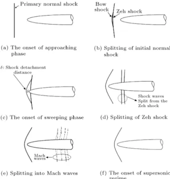
oscillation, called `buzz,' has several detrimental eects on the performance of the propulsion systems [15]. In addition, a compression wave is formed right at the cowl lip that coalesces with the bow shock downstream. From Step 4 on, the Zeh shock over the model sweeps downstream and splits into several weaker shock waves similar to what was seen for models A and B. Photos of Steps 5 and 6 clearly depict the process of trans-formation of the Zeh normal shock into two weaker ones. At Step 7, several weak normal shocks are seen that change into Mach waves at Step 8. Finally, in the last step, i.e. Step 9, all normal shocks disappear and, consequently, the overall oweld over the model surface is characterized by the supersonic ow regime. Now that the main characteristics of the su-personic phase are thoroughly investigated, a general description of the various shock waves is provided. The supersonic phase of the shock wave formation and development process begins with emergence of the initial normal shock wave. For a blunt nose body, the splitting phenomenon divides the initial normal shock into two weaker shocks, a bow, and a Zeh. In contrast, for pointed bodies, the initial normal shock reaches the nose intactly and after that, it is considered as the Zeh shock. By increasing free-stream Mach number, the bow shock stops at shock detachment distant, but the Zeh shock keeps moving downstream while persistently being split into weaker shocks. During the sweeping phase, the Zeh shock diminishes completely and, through disappearance of Mach waves, the transonic regime is completed. In Figure 8 all steps of the supersonic phase over a blunt body are categorized and demonstrated schematically. 3.4. Criterion of transition from transonic to
supersonic
As a rule of thumb, for free-stream Mach numbers in the range of 0.8 to 1.2, the ow is called transonic. The lower limit of this range is usually in proximity of the critical Mach number and, therefore, it can be representation of the rst establishment of shock waves. However, in terms of physical reasoning, the upper limit is ambiguous. It does not imply any specic behavior of the oweld to indicate the transition from transonic regime to the supersonic one. Seemingly, taking this range as transonic ow is mostly based on a force viewpoint, especially drag variations, which shows strange behaviors in this range. However, the aerodynamic forces result from the oweld features and any change in their pattern requires a physical explanation.
With regard to the shadowgraphs of the super-sonic phase, a physical interpretation is proposed to dierentiate the supersonic regime from the transonic one. According to this proposal, the complete disap-pearance of the Zeh shock, which takes place because
Figure 8. A schematic representation of supersonic phase of shock waves formation process over a general blunt body.
of the continuous splitting of shock waves, determines the onset of supersonic regime. In eect, shortly after appearance of Mach waves, the whole oweld is characterized by the supersonic ow. There is an exception for blunt bodies, where practically a small area of subsonic ow always exists and the theoretical denition of the supersonic regime (A oweld is called supersonic if Mach number is greater than 1 at every point [13].) is not applicable. However, a compromise is usually made to ignore this subsonic area behind the bow shock, because by increasing the free-stream Mach number, it gets so small that its eects on the oweld are negligible.
The extreme variations of drag force in transonic ow are well-known and, as was mentioned before, its trends are dictated by the structure of shock waves. Figure 9 depicts a typical variation of drag coecient versus free-stream Mach number, illustrating the crit-ical and drag-divergence Mach numbers accompanied by shadowgraph photos over the model to provide a physical interpretation. The critical Mach number is concurrent with the rst emergence of a sonic ow over the body and, by appearance of a strong shock, the drag coecient increases, called drag-divergence. As the free-stream Mach number reaches unity, the initial normal shock forms upstream, which results in an intensive amount of energy loss; this explains the maximum point of drag force variations. At Mach numbers higher than unity, the Zeh shock begins to split into weaker normal shocks and is substituted with oblique shocks. This mitigates the negative eect of shock waves and gradually decreases the drag force. At
Figure 9. Typical variation of drag coecient in conjunction with shock waves structure in transonic ow [16].
last, by the end of sweeping phase and disappearance of all normal shocks, less drag force is induced on the body. Based on the body conguration, drag force can increase or decrease at higher Mach numbers; however, this subject is beyond the scope of this investigation at the present time.
4. Conclusions
An experimental investigation was conducted to study the shock waves system using shadowgraph visual-ization technique. While primarily qualitative, this study provides valuable insights into the formation and development process of shock waves. In order to generalize the results, experiments were performed for three dierent models. The following specic conclusions are attained:
1. The shock waves formation and development pro-cess was categorized into two phases, namely, sub-sonic and supersub-sonic phases. This nomination is based on the free-stream Mach number. The shadowgraphs showed that for the subsonic phase, dierent shocks appeared over the model A, even though only two of them contained all the known characteristics of transonic shock waves;
2. What is normally known as the transonic regime is usually referred to as the subsonic phase and the supersonic one is almost ignored. The su-personic phase consists of two consecutive phases itself, namely, \approaching phase" and \sweeping phase." The denitions of approaching phase for blunt and sharp nose bodies were found to be dierent;
3. Splitting turned out to be the principal phe-nomenon of supersonic phase, which formed the ultimate structure of shock waves. This process proceeded forward within the sweeping phase until the Zeh shock diminished completely and the
tran-sonic regime ended. Moreover, at supertran-sonic phase, the interaction between shock waves and boundary layer became severe;
4. A physical interpretation was proposed to distin-guish between transonic and supersonic regimes. According to this denition, the complete disap-pearance of Zeh shock that happens because of splitting is the key criterion of this transition. By this explanation, the extreme trends of drag force in transonic ow were claried in terms of physical reasoning.
Acknowledgment
This work was funded partly by Sharif University of Space Technology and Transportation Research Insti-tute, Iranian Space Research Center. Their support is gratefully acknowledged. The authors wish to thank the service rendered by the sta of Qadr Aerodynamic Research Institute for carrying out all tests.
References
1. Babinsky, H. and Harvey, J.K., Shock Wave-Boundary-Layer Interactions, 20, Cambridge University Press (2011).
2. Olivier, H., Reichel, T. and Zechner, M. \Airfoil ow visualization and pressure measurements in high-Reynolds number transonic ow", AIAA Journal, 41(8), pp. 1405-1412 (2003).
3. McDevitt, J.B., Levy Jr., L.L. and Deiwert, G.S. \Transonic ow about a thick circular-arc airfoil", AIAA Journal, 14(5), pp. 606-613 (1976).
4. Mabey, D.G. \Physical phenomena associated with unsteady transonic ows", AIAA Journal, 120, Wash-ington, pp. 1-55 (1989).
5. Pearcy, H.H. \Some eects of shock-induced separation of turbulent boundary layers", in Transonic Flow Past Aerofoils, HM Stationery Oce (1959).
6. Liepmann, H.W. \The interaction between boundary layer and shock waves in transonic ow", Journal of the Aeronautical Sciences, 13(12), pp. 623-637 (1946).
7. Patz, G. \Formation of bow waves around blunt bodies in the ow behind a moving shock", Acta Mechanica, 32(1-3), pp. 89-100 (1979).
8. Davies, L., Bow-Shock Establishment and Stagnation-Point Pressure Measurement for a Blunt-Nosed Body at Supersonic Speeds, HM Stationery Oce (1965).
9. Andrews, C.D., Carlson, D.R. and Marshall, G.C, \Shadowgraphy study of the upper stage ow elds of some Saturn V study congurations in the transonic Mach number range", NASA TN D-2755, Washington, D.C. (1965).
10. Soltani, M.R., Taeibi-Rahni, M., Farahani, M., et al. \Flow measurements around a long axisymmetric body with varying cross section", 43rd AIAA Aerospace Sciences Meeting and Exhibit (2005).
11. Seegmiller, H.L., Marvin, J.G. and Levy Jr., L.L. \Steady and unsteady transonic ow", AIAA Journal, 16(12), pp. 1262-1270 (1978).
12. Ramm, H.J., Fluid Dynamics for the Study of Tran-sonic Flow, Oxford University Press (1990).
13. Heidari, M.R., Farahani, M., Soltani, M.R. and Taeibi-Rahni, M. \Investigations of supersonic ow around a long axisymmetric body", Scientia Iranica, 16(6), pp. 534-544 (2009).
14. Soltani, M.R. and Farahani, M. \Performance study of an inlet in supersonic ow", Proceedings of the Institution of Mechanical Engineers, Part G: Journal of Aerospace Engineering, 227(1), pp. 159-174 (2012).
15. Soltani, M.R., Younsi, J.S., Farahani, M. and Masoud, A. \Numerical simulation and parametric study of a supersonic intake", Proceedings of the Institution of Mechanical Engineers, Part G: Journal of Aerospace Engineering, 227(3), pp. 467-479 (2012).
16. Anderson Jr, J.D., Fundamentals of Aerodynamics, Fifth Edition, McGraw-Hill Education (2010).
Biographies
Mohammad Farahani is an Assistant Professor in the Aerospace Engineering Department of Sharif Uni-versity of Technology, Tehran, Iran. He has a PhD in Propulsion from Sharif University of Technology. His research interests include applied aerodynamics, unsteady aerodynamics, wind tunnel testing, gas dy-namics, and turbo machinery.
Amin Jaberi earned his BS degree in Aerospace Engineering from Malek-e-Ashtar University of Tech-nology and MS degree in the same subject from Sharif University of Technology. His main research interests are experimental aerodynamics, wind tunnel testing, and aircraft design.