Research Note
The Eect of an Interline Power Flow
Controller (IPFC) on Damping Inter-area
Oscillations in Interconnected Power Systems
A. Kazemi
and E. Karimi
1The eect of an Interline Power Flow Controller (IPFC) on damping low frequency oscillations has been implied in some papers, but has not been investigated in detail. This paper investigates the damping control function of an interline power ow controller installed in a power system. For this purpose, a single machine-innite bus model, integrated with IPFC, is used and the linearized model is established. Using this model, the Phillips-Heron model of the system for steady state digital simulations is derived. In this paper, the numerical results are presented using the MATLAB simulink toolbox, which shows the signicant eect of IPFC on damping inter-area oscillations.
INTRODUCTION
Low frequency oscillations, with frequencies in the range of 0.2 to 2.0 Hz, are one of the results of the interconnection of large power systems. Modern power systems are stable, if electromechanical oscillations occurring in each area can be damped as soon as possible.
The Power System Stabilizer (PSS) is a simple, eective and economical method for increasing power system oscillation stability [1].
During the last three decades, a Flexible AC Transmission System (FACTS) technology has been proposed, which provides a better utilization of the existing systems.
Due to recent trends in the creation of a deregu-lated utility industry, power transmission requirements are undergoing major changes and present considerable challenges. Deregulation is aimed at a competitive energy market, in which the sellers (producers of electric power) and buyers (distributors) are linked together with an independent transmission network. Thus, the transmission network is challenged to deliver *. Corresponding Author, Centre of Excellence for Power Systems Automation and Operation, Department of Elec-trical Engineering, Iran University of Science and Tech-nology, Tehran, I.R. Iran.
1. Centre of Excellence for Power Systems Automation and Operation, Department of Electrical Engineering, Iran University of Science and Technology, Tehran, I.R. Iran.
bulk electric power from a variety of geographically dis-persed and changing locations to the contracting buyers supplying the prevailing loads [2]. Interesting FACTS capabilities, such as power ow control, the damping of power system oscillations, voltage regulation and reactive power compensation, make them a good option for the eective utilization of power systems in this environment.
One of the FACTS capabilities is damping inter-area oscillations, which will be accurately investigated for IPFC in this paper.
The interline power ow controller, which was proposed by Gyugyi et al. [3] in 1998, is a FACTS controller for series compensation, with the unique capability of power ow management between multi-lines of a substation.
By combining two or more series-connected verters working together, the IPFC extends the con-cepts of voltage and power ow control beyond that achievable by the one-converter FACTS controller, the Static Synchronous Series Compensator (SSSC) [4]. In the IPFC structure, a number of inverters are linked to-gether at their DC terminals. Each inverter can provide series reactive compensation, as an SSSC, for its own line. However, the inverters can transfer real power between them via their common DC terminal. This capability allows the IPFC to provide both reactive and real compensation for some of the lines and, thereby, optimize the utilization of overall transmission systems. Real power can be extracted from one line and injected into another. Therefore, unlike the SSSC, the
injected voltage does not have to be in quadrature with the line current. This implies that both the voltage magnitude and the phase angle of the injected voltage can be controlled on one line. However, for proper operation of the device, the DC bus voltage must be held constant and the real power, injected to one line by the Voltage Source Converter (VSC), must be equal to the real power extracted from the other line. Hence, only one of the variables of the injected voltage of the other line can be independently controlled [5,6].
Like other FACTS elements, IPFC can be used for increasing power system stability against large and small disturbances.
In this paper, the voltage of coupling capacitance between two VSC-based converters is used as a state variable. Output power for the generator is used as an input of the PI controller, which creates a proper amplitude modulation ratio for the secondary converter.
Numerical results will show the eect of IPFC on the damping of inter-area oscillations in power systems. SYSTEM INVESTIGATED
A Single-Machine Innite-Bus (SMIB) system, with IPFC installed on two lines, is considered. This con-guration, which consists of two parallel transmission lines, connects the generator, G, to an innite bus, which is illustrated in Figure 1.
PSS is not taken into account in the power system. Operating conditions and parameters are represented in Appendix C.
DYNAMIC MODEL OF THE SYSTEM WITH IPFC
The Phillips-Heron linear model of a single-machine innite-bus system with IPFC is derived from the non-linear dierential equations. Neglecting the resistance of all the components of the system, such as generators, transformers, transmission lines and series converter transformers, a nonlinear dynamic model of the system
Figure 1. Schematic of the investigated system.
is derived as follows:
_ = !0(! 1); (1)
_! = (Pm Pe PD)=M; (2)
_E0
q= ( Eq+ Efd)=Tdo0 ; (3)
_Efd= [ Efd+ KA(Vref VS)]=TA; (4)
where:
Pe= Vsd(I1d+ I2d) + Vsq(I1q+ I2q); (5)
Pe= P1+ P2; (6)
Eq= Eq0 + (Xd Xd0)(I1d+ I2d); (7)
VS=Vsd+jVsq=XqIq+j[Eq0 Xd0(I1d+I2d)]; (8)
where:
P1: the transferred power of the primary line,
P2: the transferred power of the secondary line,
Pe: the total transferred power of the lines,
Vs: the terminal voltage of the generator,
Iid: the direct axes current of line i,
Iiq: the quadrature axes current of line i,
Xd: the direct axes reactance of the generator
and
Xq: the quadrature axes reactance of the
generator.
If the general Pulse Width Modulation (PWM) is used for VSCs, the voltage equations of the IPFC converters in the dq coordinates will be as follows [1]:
VP 1
Vq1
=
0 Xt
Xt 0
I1d
I1q
+V2dc
m1cos 1
m2cos 2
; (9)
VP 2
Vq2
=
0 Xt
Xt 0
I2d
I2q
+V2dc
m1sin 1
m2sin 2
; (10) where:
VpqK = VpK+ jVqK = VpqKejK; (11)
dVdc
dt = 3m1
4C [I1dcos 1+ I1qsin 1]
+3m4C2[I2dcos 2+ I2qsin 2]: (12)
It should be noted that using other techniques, such as space-vector modulation or optimized pulse patterns, results in the same equations as Equations 10 and 11.
From Figure 1, it can be obtained that:
This equation in the d q coordinates is as follows: VSd+ jVSq= jXS[(I1d+ I2d) + j(I1q+ I2q)]
+ jXL(I2d+ jI2q) + VP 2+ jVq2
+ Vbsin + jVbcos : (14)
On the other hand, according to Figure 2, it can be written that:
VSd= Xq(I1q+ I2q); (15)
VSq= Eq0 (Xd Xd0)(I1d+ I2d): (16)
From Equations 6 to 12, the following can be obtained:
Xds Xd0
XT L XT L
I1d I2d = E0
q V2dcm2sin 2 Vbcos Vdc
2 (m2sin 2 m1sin 1)
; (17)
Xqs Xq
XT L XT L
I1q I2q = Vdc
2 m2cos 2+Vbsin Vdc
2 (m2cos 2 m1cos 1)
;
(18) where:
Xqs = Xq+ Xs; (19)
XT L= Xt+ XL; (20)
Xds= Xd0 + Xs; (21)
Xq = Xqs+ XT L; (22)
Xd0 = Xds+ XT L; (23)
and XLis the series reactance of each transmission line.
Figure 2. Phaseor diagram of investigated system.
LINEAR DYNAMIC MODEL
Power system oscillation stability and control can be studied using a linearized model of the power sys-tems.
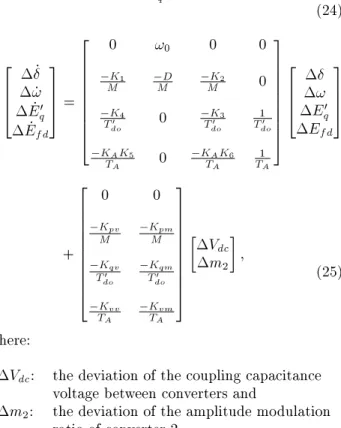
A linear dynamic model of the system, illustrated in Figure 1, is obtained by linearizing the nonlinear model of the system, presented previously around an operating condition. The linearized model is as follows:
_Vdc= K7 + K8Eq0 + K9Vdc+ Kcmm2;
(24) 2 6 6 4 _ _! _E0 q _Efd 3 7 7 5 = 2 6 6 6 6 6 6 6 6 4
0 !0 0 0
K1
M MD MK2 0
K4 T0 do 0 K3 T0 do 1 T0 do KAK5
TA 0
KAK6 TA 1 TA 3 7 7 7 7 7 7 7 7 5 2 6 6 4 ! E0 q Efd 3 7 7 5 + 2 6 6 6 6 6 6 6 6 6 4 0 0 Kpv
M KMpm
Kqv T0 do Kqm T0 do Kvv TA Kvm TA 3 7 7 7 7 7 7 7 7 7 5 Vdc m2 ; (25) where:
Vdc: the deviation of the coupling capacitance
voltage between converters and
m2: the deviation of the amplitude modulation
ratio of converter 2.
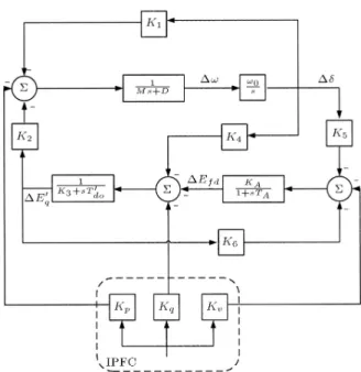
Using Equations 24 and 25, the Phillips-Heron model of the system can be obtained. Figure 3 shows this model including IPFC. This model has 16 constants, which are presented in Table 1 and are functions of the system parameters and the initial operating condition.
Table 1. Phillips-Heren model constants for system with IPFC.
Ki Value Ki Value
K1 0.3837 K5 0.0237
K2 -0.1717 K6 1.0659
Kpv 0.1092 Kvv -0.0009
Kpm 1.1562 Kvm -0.0025
K3 3.6667 K7 0.0139
K4 -0.7350 K8 -0.6890
Kqv 0.0509 K9 0.0023
Figure 3. Phillips-Heron model of a single-machine innite-bus system with IPFC controller to create a proper amplitude modulation ratio for the second converter Pe(ref)is the output power of the generator in
the operating condition [7].
POWER SYSTEM OSCILLATION DAMPING CONTROLLER
A damping controller as illustrated in Figure 4 is provided to improve the damping of power system oscillations. This damping controller consists of three cascade-connected blocks. The rst block compares the output power of the generator with reference power (Pe(ref)). Then, the error is applied to a PI.
DIGITAL SIMULATIONS
In order to understand the eect of IPFC on damping low frequency oscillations, digital simulations using the MATLAB simulink toolbox are undertaken in two cases: With and without IPFC.
When there is no IPFC in the system, the Phillips-Heron model constants are as presented in Table 2 [8]. Figures 5 to 12 show the numerical results.
Fig-Figure 4. Structure of power system oscillation damping controller.
Table 2. Phillips-Heren model constants for system without IPFC.
i Ki
1 3.2944
2 0.8533
3 1.2308
4 0.0640
5 -0.0150
6 0.9220
ures 5 to 8 illustrate power system oscillations when there is no IPFC in the system. These gures are related to the two values for the damping coecient. Figures 5 and 6 show the rotor angle deviations and rotor speed deviations, respectively, for a damping coecient equal to zero and, in Figures 7 and 8, those for a damping coecient equal to 2. In the
Figure 5. Rotor angle deviation for D = 0 without IPFC.
Figure 7. Rotor angle deviation for D = 2 without IPFC.
Figure 8. Rotor speed deviation for D = 2 without IPFC.
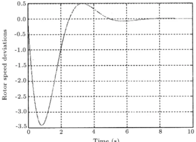
Figure 9. Rotor angle deviation for D = 0 with IPFC. same way, Figures 9 to 12 illustrate power system oscillations when IPFC is taken into account. Figures 9 and 10 show the rotor angle deviations and rotor speed deviations, respectively, for a damping coecient equal to zero and Figures 11 and 12 show those for a damping coecient equal to 2.
From these results, it can be seen that IPFC has
Figure 10. Rotor speed deviation for D = 0 with IPFC.
Figure 11. Rotor angle deviation for D = 2 with IPFC.
Figure 12. Rotor speed deviation for D = 2 with IPFC. signicant eects on damping inter-area oscillations. These eects decrease the amplitude and frequency of power system oscillations. Moreover, oscillations will be damped faster.
The results indicate, not only the superior ca-pability of the IPFC in power applications, but also suggest a powerful capacity for transient stability
improvement and power oscillation damping. CONCLUSIONS
Using a Power System Stabilizer (PSS) is a simple, eective and economical method for increasing power system oscillation stability. Although the damping duty of FACTS controllers is not often their primary function, their potential for damping low frequency oscillations has attracted interests.
The Interline Power Flow Controller (IPFC) is a FACTS controller for series compensation, with the unique capability of power ow management between multi-lines of a substation.
IPFC is a multitask controller, which plays an eective role in damping inter-area oscillations. In this paper, this function of IPFC has been investigated and numerical results have emphasized its signicant eect. In fact, even if there were no damping coecients in the power systems, the IPFC would dampen low frequency oscillations, in addition to its other capabilities.
The purpose of this paper is to illustrate damping oscillations by IPFC.
A single machine-innite bus model, integrated with IPFC, is used and the linearized model is estab-lished. Using this model, the Phillips-Heron model of the system for steady state digital simulations is derived. The results obtained from digital simulations by the MATLAB simulink toolbox, indicate that IPFC has signicant eects on the damping of inter-area oscillations.
These eects decrease the amplitude and fre-quency of power system oscillations. Therefore, oscil-lations will be damped faster.
The results indicate the superior capability of the IPFC in power applications and suggest a powerful capacity for transient stability improvement and power oscillation damping.
Only one of the variables of the injected voltage of the other line can be independently controlled. The voltage of coupling capacitance between two VSC-based converters is used as a state variable and the output power of the generators is a proper feedback for constructing an amplitude modulation ratio for the second converter.
REFERENCES
1. Yong Hua Song and Allan T. Johns, Flexible AC Transmission Systems (FACTS), IEE Press, London, UK (1999).
2. Gyugyi, L. \Application characteristics of converter-based FACTS controllers", IEE Proc. 2000, Gener.,Transm., Distrib., pp 391-395 (2000).
3. Gyugyi et al. \The interline power ow controller concept: A new approach to power ow management in
transmission systems", IEEE Transactions on Power Delivery, 14(3), pp 1115-1123 (July 1999).
4. Zhang, X.P. \Modelling of the interline power ow con-troller and the generalized unied power ow concon-troller in newton power ow", IEE Proc.-Gener Transm., Distrib., 150(3), pp 268-276 (May 2003).
5. Valencia, V.D., Annakkage, U.D., Gole, A.M. and Demchenlko, P. \Interline power ow controller (IPFC) steady state operation", IEEE Proceed. Cana-dian Conference on Electrical & Computer Engineer-ing, pp 280-284 (2002).
6. Hang, H.F. \Design of SSSC damping controller to improve power system oscillation stability", IEEE 0-7803-5546-6/99, pp 495-500 (1999).
7. Tambey, N. and Kothari, M.L. \Damping of power system oscillation with unied power ow controller", IEE Proc.-Gener. Transm. Distrib., 150(2), pp 129-140 (March 2003).
8. Yao-nan, Y., Electric Power System Dynamics, New York, Academic Press, Inc. (1983).
APPENDIX A
MATLAB simulink block diagram for simulation with-out IPFC (Figure A1).
APPENDIX B
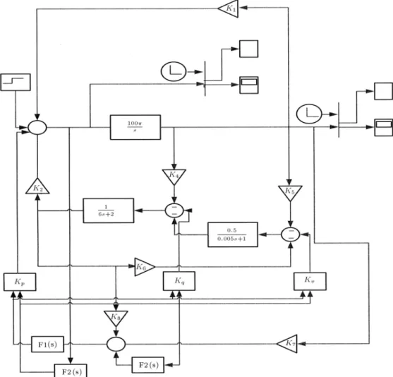
MATLAB simulink block diagram for simulation with IPFC (Figure B1).
APPENDIX C
Operating conditions and parameters are as follows: Generator:
M = 2H = 6 s; D = 2; T0
do= 5:044 s;
Xd=0:1 pu; Xd0=0:025 pu; Xq=0:06 pu:
Excitation system:
KA= 0:5; TA= 0:005 s:
Converter transformers: Xt= 0:1 pu:
Converter parameters:
m1=0:15; 1=15; m2=0:10; 2=22:
Transmission line transformers: XL= 0:2 pu; XS= 0:2 pu:
DC link parameters:
Figure A1. MATLAB simulink block diagram for simulation without IPFC