ISSN: 2252-8938 72
Mitigation of Voltage Fluctuations Using Fuzzy-Based
D-STATCOM in High Level Penetration of DG Systems
M. Padma Lalitha, R. Madhan Mohan, B. Murali Mohan Babu
Department of Electrical and Electronic Engineering AITS, JNT University Anantapur, Rajampet, Andhra Pradesh, India
Article Info ABSTRACT
Article history: Received Feb 7, 2016 Revised April 10, 2016 Accepted May 11, 2016
Voltage fluctuations mainly resulting from variable output power of renewable energy sources; these are strictly challenging power quality in distribution-generation systems. The paper presents a control method for fuzzy based D-STATCOM to relieve variation of positive-sequence and negative-sequence voltages. D-STATCOM continuously operates as fundamental positive–sequence admittance and negative-sequence conductance to restore the positive-sequence voltage to the nominal value and negative-sequence voltage to the allowable level. At transient period both admittance and conductance are dynamically tuned to improve the voltage regulation performance. The ability of fuzzy logic to handle rough and unpredictable real world data made it suitable for a wide variety of applications, especially, when the models are too complex to be analyzed by classical methods. This paper presents the computer simulation of fuzzy based D-STATCOM under steady and transient state condition. The reduction of total harmonic distortions (THD) and voltage imbalance factor %VUF is discussed at all buses and maintained in acceptable level.
Keyword:
D-STATCOM, Voltage imbalance, Voltage fluctuations, Fuzzy controller
Copyright © 2015 Institute of Advanced Engineering and Science. All rights reserved.
Corresponding Author: M. Padma Lalitha,
Department of Electrical and Electronic Engineering AITS, JNT University Anantapur, Rajampet, Andhra Pradesh, India. Email: [email protected]
1. INTRODUCTION
In The concept of micro-grid was proposed to coordinate various renewable energy sources (RESs) into distribution networks for both grid-connected and islanding operations. Increasing the use of RESs could help to relief network congestion; reduce system losses, and different infrastructure investments. These problems have received much attention recently, and numerous projects have developed by the functionality of micro grid. Conventionally, voltage fluctuations mainly resulting from impedance of transmission lines, uneven distribution of single-phase loads, and loading types. In the low voltage micro-grid system these scenarios become much severe due to reverse power flow provided by distributed generations (DGs) in either single or three-phase connection.
Voltage fluctuations cause the system losses, transformer overloading, capacity reduction and motor overheating, and even results in output limitation of DGs, and malfunction of sensitive equipment, nuisance tripping of protected devices. According to IEEE Std 1547.2-2008 [9], the limitation of voltage fluctuations are up to ±5% as RESs are paralleled to low-voltage systems. Voltage imbalance is measured by %Unbalance i.e %VUF kept below 2.0%–3.0% is acceptable for both utility and manufactures, where %VUF are defined as the ratio of the negative-sequence voltage to the positive sequence voltage, and percentage of maximum deviation from the average value, respectively. Therefore, in grid connected operation voltage regulation is absolutely needed to permit more DGs.
order to achieve efficient utilization of D-STATCOM [11]. Most of the controllers used for this device are based on the PI controller shown in figure 2. Although the PI controllers are simple and easy to design, their performance deteriorates when the system operating conditions vary widely and large disturbances occur. Unlike the PI controllers, fuzzy logic controllers (FLCs) [17] are capable of tolerating uncertainty and imprecision to a greater extent. So, they produce good results under changing operating conditions and uncertainties in system parameters.
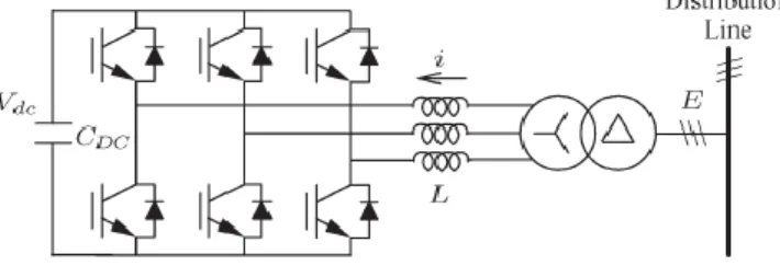
2. D-STATCOM AND OPERATION PRINCIPLE
The basic configuration of D-STATCOM as shown in figure1, it consists of three-phase voltage source inverter using IGBT, DC voltage source and connected to the distribution line by coupling transformer. The D-STATCOM operates as fundamental positive-sequence admittance and negative-sequence conductance as given
i*=Y p*.E f + + G n*.E f – (1)
Where i* is the reference current, E f+ and E f– are the fundamental positive-sequence and
fundamental negative-sequence voltage. Y p* and G n* are the fundamental positive-sequence admittance and
negative-sequence conductance are defined variable control gains to furnish regulating positive-sequence voltage and suppressing imbalanced voltage.
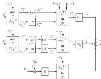
Figure 2. Generation of Reference Current
2.1. Generation of Reference-current
According to synchronous reference frame (SRF) transformation the control is actualized as shown in Figure 2.
By using low-pass filter (LPF) to filter out ripple components and the positive-sequence voltage Eqd
+e
is obtained. The negative-sequence-voltage Eqd –e
is determined by the combination of LPF and a band rejected filter tuned at the second order frequency. From the Figure 2, the quadrature fundamental positive-sequence voltage E f+ and negative-sequence voltage Ef– is available by applying reverse transformation. The
positive-sequence current i f*+ is equal to E f + multiplied by Yp*and negative-sequence current I f *- are equal
to E f –
multiplied by G n *
, respectively. Thus, the (1) is generated as a current command i * .A dc voltage control is also designed for secure operation of the D-STATCOM. The fundamental current produced by the PI regulator which is in-phase with the positive-sequence voltage to maintain the dc voltage V dc at the
reference value V dc*.
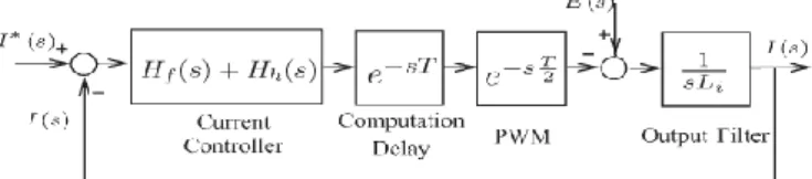
2.2. Current Control
Figure 3. Shows a current regulator produces the voltage command v * based on the current command i *, the measured voltage E and measured current I for space vector pulse width modulation (PWM) control of the invertor. The transfer functions H h(s) and H f(s) as given as
( )
(2)
( ) ∑
Figure 3. Current Control
Where Ki,f and ωf are the fundamental integral gain and its frequency, respectively; kp represents a proportional gain; and ωh and Ki,h represent the harmonic frequency and its integral gain, respectively. The damping ratio ξ has tuned current regulator it introduce various narrow gain peaks at the harmonic
2.3. Tuning Control
The tuning control of both Gn* and Yp* as shown in figure 5.Ef+ and Ef– are defined as (3).By using
LPF and SQRT operation they can approximately calculated, where LPF designed with cut-off frequency w c
=10 HZ. Then, a PI regulator is actualize to generate Y*p to maintain Ef+ at nominal value Ef+*.Similarly by
controlling of Gn *
the imbalanced voltage could be suppressed and maintained at an allowable level. The percentage of voltage unbalance factor (%VUF) is to estimate the level of imbalance voltage. %VUF is defined ad the ratio of negative-sequence voltage to the positive-sequence voltage and as given as (4).
| | √∫ (
( ) ( ) )
| | √∫ ( ( ) ( ))
(3)
%VUF=| |
| | .100% (4)
Basically, three control loops in the proposed system. The bandwidth of the current control loop, which depends on the switching frequency of the inverter. The current command is generated by the tuning of both admittance and conductance to improve the power quality. So their band widths are lower than that of current loop. To control both admittance and conductance by the tuning of PI parameters with suitable transient response and zero steady state error. Due to inverter loses the voltage on the dc capacitor will fluctuate and imbalanced voltage suppressed by conductance. Lower the dc capacitance, larger fluctuations will happen. Generally, the bandwidth of dc voltage control is lowest due to large capacitance in the system.
Figure 5. Tuning Control of Yp* and Gn*
3. FUZZY LOGIC CONTROLLER (FLC)
The disadvantage of PI controller is its inability to react to sudden changes in the error signal, ε, because it is only capable of determining the arising value of the error signal without considering the change
logic control as it is shown in Figure 6 is proposed. The determination of the output control signal, is done in an inference engine with a rule base having if-then rules in the form of
IF ε is ...AND Δε is ..., THEN output is...
Figure 6. Basic Representation of the Fuzzy Logic Controller (FLC)
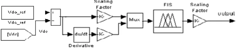
With the rule base, the value of the output is changed according to the value of the error signal ε, and the rate-of-error Δε. The structure and determination of the rule base is done using trial-and-error methods [17] and is also done through experimentation. The MATLAB/SIMULINK model of fuzzy logic controller is shown in figure 7.
Figure 7. MATLAB/SIMULINK Model of Fuzzy Logic Controller.
4. SIMULATION STUDIES
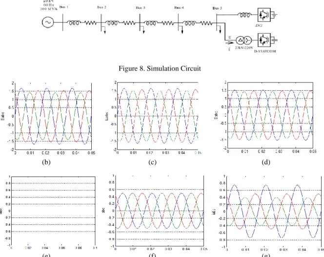
A radial line as shown in figure 8.which is rated at 23 kv and 100MV, it is established by using alternate transient program to illustration of voltage fluctuations and verify the effectiveness of the D-STATCOM. At the end of radial line the grid voltage is sensitive to injection of both real and reactive power based on load flow analysis, therefore D-STATCOM installed at the end of the line. Table 1 and 2 are the line and load data, respectively.
The parameters of D-STATCOM given as follows.
1) Voltage base: 23kv, current base: 2510 A, and impedance base: 5.28 Ω. 2) PWM frequency: 10 kHz.
3) The reference fundamental positive-sequence voltage |E+f|= 1.0 p.u. and voltage unbalance factor % VUF =2.0%.
4) Current controller: ki,h = ki,f= 40 (for h=5,7,11 and 13), kp = 25, and ξ = 0.001.
5) Tuning controller: PI parameters for |E+f| ( kp = 0.001, ki = 1*10-4 ) and for %VUF (k p = 10 and ki =
0.05).
Note that at the end of the bus inverter-based DG is to be installed and single-phase loads are connected between a and b phases to generate sever voltage variation as well as voltage imbalance. The PI regulator is controlling the power of DG it produce current command. But FLC is used in the D-STATCOM current control; to regulate the output current of the DG is realized by resonant current control. The control of the DG has already studied [8].
4.1. Steady-State Operation
Before starting of the D-STATCOM operation, the bus voltages are significantly swelled and imbalanced due to single-phase loads and DG as shown in Figure 9(b). At the end of the line, the voltage fluctuations are worse condition. For example at Bus 5, |E+f| = 1.06 p.u. and %VUF = 5.1% . Table 3 shows corresponding |E+f| and %VUF for all buses. When the fuzzy based D-STATCOM is initiated with compensation of the positive-sequence voltage only (G∗
n= 0), then Table 4 shows the |E
+
f| on each bus could be restored to the nominal value. At this time, the D-STATCOM is operated at Y ∗
p = 0.37 p.u. with rms currents ia= ib= ic= 0.37 p.u. However, the voltage fluctuation is still significant as shown in figure 9(c) due to imbalanced voltage. After imbalance suppression is activated, the bus voltages are clearly recovered from
power of the D-STATCOM are reduced, due to swelled voltage becomes slighter. More interestingly, at t= 9 s the DG being turned off then |E+f| becomes lower than 1.0 p.u. In these condition, the fuzzy based D-STATCOM operates with reduced Yp* for increasing voltage.
Figure 8. Simulation Circuit
(b) (c) (d)
(e) (f) (g)
Figure 9. Test results (b) D-STATCOM off. (c) D-STATCOM on, but Gn*= 0. (d) STATCOM on. (e)
Table 1. Line Data (in per unit) Table 2. Load Data (in per unit) Line
segment
R X
Bus 1-2 0.030 0.033
Bus 2-3 0.049 0.049
Bus 3-4 0.034 0.039
Bus 4-5 0.021 0.030
Bus 3 P 3 Q 3
rectifier 3 DG
1 P
2 0.052 0.032 0.106ab
3 0.051 0.024 0.106ab
4 0.003 0.017 0.092 0.106ab
5 0.014 0.007 0.9 0.106ab
Table 3. Bus Voltages after D-STATCOM only Compensates Positive-Sequence Voltages
Table 4. Bus Voltages Before The D-STATCOM is Started
BUS 2 BUS 3 BUS 4 BUS 5
| | 1.00 1.02 1.04 1.06
%VUF 1.8% 3.7% 4.8% 5.1%
BUS 2 BUS 3 BUS 4 BUS 5
| | 1.00 1.00 1.00 1.00
%VUF 1.8% 3.7% 4.8% 5.1%
Table 5. Bus Voltages After the D-STATCOM Compensates Both Positive and Negative-Sequence
Voltages
BUS 2 BUS 3 BUS 4 BUS 5
| | 1.00 1.00 1.00 1.00
%VUF 1.7% 1.9% 2.0% 2.0%
Table 6. Load OR DG Variation
t Event Location
4 3 load off Bus 3
6 3 load off Bus 4
7 1 load off Bus 4
8 DG output from 0.9to 0.45 p.u. Bus 5 9 DG output from 0.45to 0 p.u. Bus 5
(a) (b)
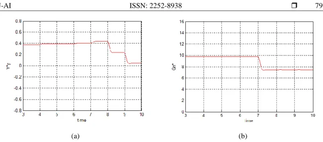
Figure 10. Voltages in Transient Operation, (a)|E+f|. (b) %VUF.
Therefore, the voltage regulation could be sophisticated by dynamically tuning Yp* and Gn* of the
fuzzy based D-STATCOM. From the above simulations, it is clear and obvious that the proposed fuzzy controller is able to control the DC-bus voltage efficiently in steady or transient state.
Figure 11. D-STATCOM Commands in Transient Operation. (a) Yp*. (b) Gn*.
5. CONCLUSION
The paper has presented the alleviation of voltage fluctuations at steady state and transient state based on fuzzy logic control method of D-STATCOM in high level penetration of DG systems. Together with positive-sequence admittance to recover the positive-sequence voltage, negative sequence conductance is implemented to cooperatively improve imbalanced voltage. A tuning control is designed to dynamically adjust admittance as well as conductance commands to maintain both positive and negative-sequence voltages at an allowable level in response to power variation of DGs or loads. The reduction of total harmonic distortions (THD) and percentage of unbalance factor (%VUF) maintained at all buses in an acceptable levels. One of the major advantages of this scheme is being less sensitive to the system parameters variation; in addition, it is characterized by a negligible response time. Simulation results analysis has shown that the proposed controller has fast dynamic response, high accuracy of tracking the DC-voltage reference, and strong robustness to load sudden variations.
REFERENCES
[1] D Westermann, M Kratz. A real-time development platform for the next generation of power system control functions. IEEE Trans. Ind.Electron., 2010; 57(4): 1159–1166.
[2] TL Lee, SHHu, YH Chan. Design of D-STATCOM for voltage regulation in micro-grids. In Proc. IEEE Energy Convers.Congr.Expo. 2010: 3456–3463.
[3] S Dib, C Benachaiba, B Ferdi. Transient Performance Improvement of Dynamic Voltage Restorer by Adaptive Fuzzy PI Controller. International Review on Modelling and Simulations (I.RE.MO.S). 2009; 2(2).
[4] T Senjyu, Y Miyazato, A Yona, N Urasaki, T Funabashi. Optimal-distribution voltage control and coordination with distributed generation. IEEE Trans. Power Del., 2008; 23(2): 1236–1242.
[5] YR. Mohamed, E El-Saadany. A control scheme for PWM voltagesourcedistributed-generation inverters for fast load-voltage regulation andeffective mitigation of unbalanced voltage disturbances. IEEE Trans. Ind.Electron., 2008; 55(5): 2072–2084.
[6] P Carvalho, P Correia, L Ferreira. Distributed reactive power generation control for voltage rise mitigation in distribution networks. IEEETrans. Power Syst. 2008; 23(2)766–772.
[7] H Fujita, H Akagi. Voltage-regulation performance of a shunt active filter intended for installation on a power distribution system. IEEETrans. Power Electron. 2007; 22(3): 1046–1053.
[8] TL Lee, PT Cheng. Design of a new cooperative harmonic filtering strategy for distributed generation interface converters in an islanding network. IEEE Trans. Power Electron. 2007; 42(5): 1301–1309.
[9] F Blaabjerg, R Teodorescu, M Liserre, AV Timbus. Overview of control and grid synchronization for distributed power generation systems. IEEE Trans. Ind. Electron. 2006; 53(5): 1398–1409.
[10] E Twining, MJ Newman, PC Loh, DG Holmes. Voltage compensation in weak distribution networks using a D-STATCOM. In Proc. IEEE PEDS, 2003: 178–183.
[11] PS Sensarma, KR Padiyar, V Ramanarayanan. Analysis and performance evaluation of a distribution STATCOM for compensating voltage fluctuations. IEEE Trans. Power Del., 2001; 16(2): 259–264.
[12] Mohammad Mohammadi, Ashkan Mohammadi Rozbahani, Mahdi Montazeri, Hamed Memarnezhad, Saman Abasi Garavand. Fuzzy Bang-Bang Control Scheme of USSC for Voltage Sag Mitigation Due to Short Circuits and Induction Motor Starting in Distribution System. Iaes journal, 2014; 4(4).
[13] Deepthisree Madathil, Ilango Karuppasamy, Kirthika Devi VS, Manjula G Nair. Voltage Flicker Mitigation in Electric Arc Furnace using D-STATCOM. iaes journal, 2014; 5(2).
BIOGRAPHIES OF AUTHORS
1
M. Padma Lalitha is graduated from JNTU, Anathapur in Electrical & Electronics Engineeringin the year 1994. Obtained Post graduate degree in PSOC from S.V.U, Tirupathi in the year 2002. Having 14 years of experience in teaching in graduate and post graduate level. She had 10 international journal publications and 10 international and national conferences to her credit. Shepublished nearly 54 papers in various national & international journals & conferences. S.V.University, Tirupathi awarded doctorate in the year 2011 Presently working as Professor and HOD of EEE department in Annamacharya Institute of Technology and Sciences, Rajampet Andhra Pradesh, India. Areas of interest include radial distribution systems, ANN. Mail id: [email protected]
2
R. Madhan mohan was born on rajampet, Kadapa, India. He received the B.E& M.E degrees in electrical and electronic engineering from JNTUA, AITS in 2006, 2009. Presently working as Assistant Professor in EEEdepartmentinAnnamacharya Institute of Technology and Sciences, Rajampet, Andhra Pradesh, India. Area of interest power systems.
Mail id: [email protected]
3B.Muralimohan babu was born in 1992. He received B.Tech Degree from Siddhartha institute of
engineering and technology, JNTUniversity Anantapur, puttur In the year 2009. At present persuing M.Tech in power systems from Annamacharya Institute of Technology and Sciences, Rajampet, Andhra Pradesh, India. Area of interest distribution systems.