TECHNICAL UNIVERSITY OF CLUJ-NAPOCA
ACTA TECHNICA NAPOCENSIS
Series: Applied Mathematics, Mechanics, and Engineering Vol. 61, Issue II, June, 2018
INFLUENCE OF WORKING FLUID PRESSURE ON THE POWER
OF A STIRLING GAMMA ENGINE
Adrian Ioan BOTEAN
Abstract: This study aims to highlight the influence of working fluid pressure (fot this application being
air) on the power developed by a Stirling gamma engine whose total cylinder capacity is 36.796 cm3. For
an experimental determination of power an electric DC motor is used. It operates in the start – up mode (puts into motion the Stirling engine), the electric generator mode – specific for the whole Stirling engine running time and the braking mode when the electric motor is powered by an external power supply and by measuring voltage and electric current absorbed by the electric motor determines the power developed by the Stirling engine. Analytically, the power developed by the Stirling engine is determined by the mathematical models presented in the technical literature.
Key words: gamma Stirling engine, pressure, temperature, working fluid, power, speed, thermodynamic
cycle
1. INTRODUCTION
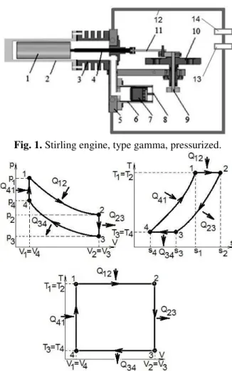
In this study we are trying to determine the power developed by a Stirling engine of the gamma type having as variable parameter the pressure of the working fluid. The constructed design uses air as a working fluid. Figure 1 show the composition of the Stirling engine of the gamma type, with a total cylinder capacity of 36.796 cm3 (slightly modified version compared to the one presented in works [1] and [2]), as follows: 1 – expansion piston (displacer); 2 – the cylinder of the expansion piston / the hot heat exchanger; 3 – radiator / cold heat exchanger; 4 – the con – rod of the expansion piston; 5 – plate; 6 – cylinder of the working piston; 7 – working piston; 8 – the con – rod of the working piston; 9 – the crank of the working piston; 10 – flywheel; 11 – the crank of the expansion piston; 12 – pressurized enclosure; 13 – pressure transducer; 14 – inlet valve for working fluid.
To understand how the working fluid pressure influences the power developed by the Stirling gamma engine, its theoretical operating cycle [3, 4, 5], according to Figure 2 and Figure 3 should be analyzed.
Fig. 1. Stirling engine, type gamma, pressurized.
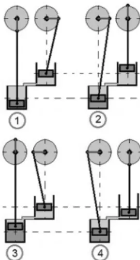
The theoretical cycle of a Stirling engine consists of two isotherms and two isocores. When moving the piston 1, according to Figure 1, there is an isothermal 1 – 2 expansion of the working fluid (Figure 2 and Figure 3) in which case the Stirling engine absorbs from the heating system a thermal energy expressed through the following relationship:
∙ ∙ ∙
∙ ∙ 1 where: m is the mass of the working fluid and R is the perfect gas constant for the working fluid. Simultaneously with the displacement of the power piston (Figure 1 and Figure 3) takes place the dispacement of the power piston 7 (Figure 1 and Figure 3) produces a migration of the working fluid to the area of the power cylinder 6 which receives, by means of heating, thermal energy Q23. Since the movement of the two pistons is synchronized by means of the crank shaft mechanism, the transformation recorded by the working fluid is an isocorous (range 2 – 3 of Figure 2). Thus, the working fluid decreases the temperature and pressure. In the next step the force piston 7 performs isothermal compression (range 3 – 4 in Figure 2 and position 3 of Figure 3) and the working fluid yields the Q34 heat energy to the cold source represented by the radiator 3 of Figure 1. The thermal energy given to the cold source is expressed through the following relationship:
∙ ∙ ∙
∙ ∙ 2 At the next moment of the operating cycle the isochoric transformation 4 – 1 is performed during which the working fluid accumulates the thermal energy from the hot source and the elements in the area of the force cylinder cool down. In this case the thermal energy taken up by the working fluid is expressed through the following relation:
∙ ∙ 3 The mechanical work L produced by the Stirling engine is expressed by:
∙ ∙ ∙ ∙
∙ ∙ 4
Stirling’s thermal efficiency is calculated with:
1 5
Analyzing relations 4 and 5 in terms of the objective of the study in this paper follows that mass and specific heat of the working fluid plays a decisive role. Specific heat varies depending on the nature of the working fluid. For example, for air cV=838.2[J/kgK], for helium cV=5,193[J/kgK] and for hydrogen cV=14,307[J/kgK]. So, for the same value of the pressure inside the Stirling engine using different working fluids different powers and thermal efficiency are obtained. In order to have a larger mass m in the working space a higher working fluid pressure is required. This raises a number of challanges in terms of sealing the workspace as much as possible. The more sealing the more friction forces increase resulting the lower Stirling engine power.
2. METHODS
For the constructive design of the Stirling engine analyzed, with the aim of reducing friction forces, it was not possible to achieve a proper seal of the expansion piston rod for which a sealing chamber made of epoxy resin was built, including the distribution mechanism according to Figure 1 and Figure 4. For the assessment of engine power developed by pressure, an experimental stand presented in Figure 4 was designed.
Fig. 3. The positions of the expansion and power pistons of the Stirling gamma engine over a period of
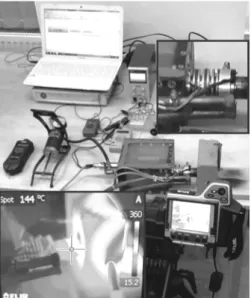
Fig.4 Experimental installation for determining the power of a Stirling gamma engine according to the
working fluid pressure.
Figure 5 shows the block diagram of the experimental installation consisting of the following elements: 1 – the gamma Stirling engine; 2 – digital laser tachometer (DT – 1236L); 3 – digital thermal imaging camera (FLIR – T400); 4 – the breadbord used to make connections for the digital multimeters (voltmeter and ammeter) and the selection of the operating mode of the electric DC motor; 5 – voltmeter and ammeter; 6 – DC power source with variable voltage; 7 – data acquisition system (HBM Spyder 8); 8 – graphical interface to the CatmanEasy – AP (HBM) software; 9 – temperature transducer (Pt100 thermal resistance); 10 – water cooling system; 11 – pressure sensor (HBM P3MB).
Fig.5 Block diagram of the experimental installation for determining the power of a Stirling engine of the gamma type according to the working fluid pressure.
On the shaft of the crank – shaft mechanism was mounted an DC electric motor which plays a triple role: starter motor – the DC motor powered by the digital power supply (reference 6 in Figure 5) will put the Stirling
engine in motion; DC generator – the Stirling engine during its operation will produce a useful mechanical work taken over by the DC electric motor and transformed into electric energy; brake – by changing the DC polarity of the DC motor, it will tend to reverse the direction of rotation of the Stirling engine crank mechanism, thus producing a braking effect.
When the DC motor acts as a braking device, the electrical current and the electrical voltage are monitored (by means of an ammeter and a digital voltmeter – reference 5 in Figure 5) absorbed from the power supply, thus assessing the power developed by the Stirling engine. The Stirling engine speed is measured using the digital tachometer 2 (Figure 5). The heat source temperature is monitored by means of a thermal imaging camera (reference 3 in Figure 5) and the temperature distribution in the radiator area (reference 3 in Figure 1) is monitored by means of two Pt100 thermal resistors (reference 9 in Figure 5). The radiator is connected to the water supply system (reference 10 in Figure 5). The expansion cylinder 2 (Figure 1) is inserted into a ceramic enclosure and heated by a gas burner. The enclosure made of ceramic material has the role of reducing heat loss. The pressure in the pressurized enclosure is monitored by means of a pressure transducer (reference 11 in Figure 5). Both the pressure transducer and the temperature transducers are connected to the Spyder 8 acquisition system (reference 8 in Figure 5) and the data are graphically visualized by the CatmanEasy – AP software (reference 7 in Figure 5).
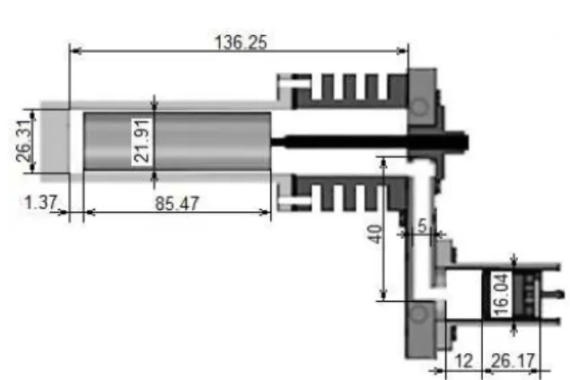
Fig.6 Dimensional characteristics of the gamma Stirling engine analyzed.
3. RESULTS
Numerous studies of the thermodynamic cycle have been published in the technical literature to determine the power developed by the Stirling engine [6, 7, 8]. The results of this study, obtained by the experimental test, are compared with a set of analytical results based on mathematical models presented in papers [9, 10, 11].
In the pressurized enclosure (Figure 1, reference 12), using air as the working agent, a pressure load of 1, 1.4, 1.6 and 2.3 bar was carried out, monitored by means of the P3MB pressure transducer (reference 13 from Figure 1 and reference 11 of Figure 5). Table 1 gives the values of the temperature of the hot source (monitored by means of the thermal imaging camera – reference 3 of Figure 5), the cold source temperature values (monitored by means of the Pt100 thermal resistors – reference 9 in Figure 5), the speed at which the power is
obtained (monitored using the DT – 1236L digital tachometer – reference 2 of Figure 5), the maximum power values developed by the Stirling engine obtained experimentally and analytically, and the last column calculated the relative deviation between the sets of results. The radiator (reference 3 in Figure 1), which has the function of cooling the working fluid, has two zones in which the temperature has maximum and minimum values. The minimum temperature zone is generally referred to as the cold source and the maximum temperature zone is generally called the hot zone, the temperature gradient between the two areas being monitored by means of the two Pt100 thermoresistance. Figure 7 shows the temperature variation of the cold source temperature versus time, and in Figure 8 is plotted the temperature variation of the hot source according to time. From the two charts we can see that the temperature presents a nonliniar variation law in the range 0 – 27 minutes after which the temperature regime stabilizes the diagram having an approximate variation law.
Figure 9 shows the diagram of the speed variation according to the cold source temperature, and in Figure 10 the speed variation diagram is plotted according to the temperature of the hot source. Starting from the two figures, it can be mentioned that when the Stirling engine reaches a constant operating mode (temperature and constant speed) the DC motor will pass from the generator mode to the braking mode thus being able to determine the power developed by the Stirling engine.
Table 1
The experimental and theoretical results obtained. Pressure,
[bar]
Hot source temperature,
[oC]
Cold source temperature,
[oC]
Speed, [rot/min]
Power developed, experimentally, [W]
Power developed, theoretically, [W]
Relative deviation,
[%]
1 185 51.93 333.7 2.71 2.84 4.57
1.4 186 51.85 396.3 3.63 3.861 5.98
1.6 197 47.86 240.8 4.18 4.65 10.1
2.3 174 45.78 288.8 6.87 7.183 4.35
Figure 11 shows the speed variation diagram based on time for Stirling engine. From this figure it can be seen that after about 27 minutes the Stirling engine reaches a stabilized operating mode. With the electric engine running in braking mode, it can be noticed that the Stirling engine speed is decreasing and the
power developed will have maximum values at a lower engine speed, as shown in Figure 12.
Fig.7 Diagram of the cold source temperature variation versus time.
Fig.8 Diagram of the hot source temperature variation versus time.
Fig.9 Speed variation diagram depending on the cold source temperature
Fig.11 Speed variation diagram according to time.
Fig.12 Power variation diagram developed by the Stirling engine according to speed.
Also, the higher the temperature difference between hot source (T3) and cold source (T1) – theoretically – the mechanical work will have high values. In fact, the higher the temperature gradient, fuel consumption may be higher. So, it is necessary to identify an optimal temperature gradient so that the efficiency of the Stirling engine is superior.
For the four tests performed in this study an average fuel gas mass of 36.5 grams was used and the duration of each test was about 35 minutes. In absolute terms for a 140 minutes operating period a 146 grams of fuel was consumed, this being about 1,042 grams per minute.
4. CONCLUSIONS
As is known, the Stirling engine is an external combustion engine having a closed cycle, particurlarly regenerative, which operates through a succession of compression and expansion cycles of the working fluid produced by the difference of temperature between the hot source and the cold source and by means of a crank – shaft mechanism the conversion of thermal energy into mechanical energy is achieved. The main element that allows the operation of the Stirling engine is the radiator (reference 3 in Figure 1) which is actually a heat exchanger. For some applications, the use of a second heat exchager called generic heat regenerator can achieve a higher value of potential output.
tank. The burner is inserted into a refractory brick enclosure (Figure 4), aiming at minimizing heat losses.
Following the experimental attempts and the interpretation of the obtained results the following conclusions can be drawn: when reaching a constant operating mode for which the cold and hot source temperatures are constant, the power developed by the Stirling engine increases with the increase the wotking fluid pressure; the power reaches a maximum when a working fluid pressure of more than 2.3 bar is reached; the speed decreases with the increase the working fluid pressure; to increase the pressure the heat transfer in the radiator area is made more difficult because the number of thermally charged molecules is higher. To increase Stirling engine power, if the total volume and the temperature gradient between the hot and the cold source is considered constant, another working fluid may be used.
5. ACKNOWLEDGEMENTS
This study was made possible by the technical support given by: Hiticaş Iacob Otniel, Rȋnziş Emanuel and Pupeză Gheorghe students at the Technical University of Cluj Napoca, Romania.
6. REFERENCES
[1] Botean, A.I., Florescu, M., Glogoveţan, A., Vitan, V., The functional analysis of a gamma
type Stirling engine, Acta Technica
Napocensis, Series: Applied Mathematics,
Mechanics, and Engineering, Vol.59, Issue I, March, 2016, 53-58.
[2] Botean, A.I., Hiticaş, I., Experimental power
determination of a gamma type Stirling engine, Acta Technica Napocensis, Series: Applied Mathematics, Mechanics, and Engineering, Vol.60, Issue I, March, 2017, 103-108.
[3] Hell, F., Thermische Energietechnick, VDI. Verlog, Dusseldorf, 1986.
[4] Kaltschmitt, M., Energiegewinnung aus
Biomasse in kontext des deutschen Energiesystems, Energieanwendung, s19-25, No.1 Ian/Febr, 1995.
[5] Mădărăşan, T., Bazele termotehnicii, Ed. Sincron, Cluj – Napoca, 1998.
[6] Tew, R., Jefferies, K., Miao, D., A Stirling
engine computer model for performance calculations, National Aeronautics and Space Administration Lewis Research Center, 1978.
[7] Formosa, F., Despesse, G., Analytical model
for Stirling cycle machine design, Energy Conversion and Management, 51 (2010) 1855-1863.
[8] Walker, G., Stirling Engines, Oxford: Clarendon Press, 1980.
[9] Schmith, G., Classical analysis of operation
of Stirling engine. A report published in German Engineering. Union (Original German), vol. XV (1871), 1987, 1-12. [10] Hirata, K., Schmidt theory for Stirling
engines, National Maritime Research
Institute, http://nmri.go.jp /env/khirata/ [11] www.robertstirlingengine.com/theory.php
Influența presiunii fluidului de lucru asupra puterii unui motor Stirling de tip gamma
Rezumat: În acest studiu se urmăreşte evidenţierea influenţei presiunii fluidului de lucru (pentru această aplicaţie fiind
aerul) asupra puterii dezvoltate de către un motor Stirling de tip gamma a cărei cilindree totale este de 36.796 cm3.
Pentru determinarea experimentală a puterii se utilizează un motor electric de curent continuu care funcţionează ȋn regim de demaror (pune ȋn mişcare mecanismul motor al motorului Stirling), regim de generator electric – specific pentru ȋntreaga durată de funcţionare a motorului Stirling şi regim de frânare când motorul electric este alimentat de la o sursă de alimentare externă iar prin măsurarea tensiunii şi a curentului electric absorbit de motorul electric se determină puterea dezvoltată de motorul Stirling. Analitic, puterea dezvoltată de motorul Stirling se determină cu ajutorul modelelor matematice prezentate ȋn literatura de specialitate.
Adrian Ioan BOTEAN, Lecturer, Ph.D., Technical University of Cluj-Napoca, Department of Mechanical
Engineering, 103-105 Muncii Blvd., 400641, Cluj-Napoca, +40-264-401751,