DIGITAL HOLOGRAFIC INTERFEROMETRY USED FOR
IDENTIFICATION OF 2D TEMPERATURE FIELD
Vít LÉDL•, Tomáš VÍT, Roman DOLEČEK, Pavel PSOTA,
Abstract: The presented paper shows the possibility of digital holographic
interferometry application in measurement of unsteady 2D temperature field generated by pulsatile flow which is impinging heated surface. Special holographic setup with double sensitivity was developed instead of the commonly used Mach-Zehnder type of holographic interferometer in order to attain the parameters sufficient for the studied case. This setup is not light efficient like the Mach-Zehnder type but has double sensitivity. The results from the digital holographic interferometry experiments are perfected by measurement of the velocity field achieved by methods of hot-wire anemometry.
1. INTRODUCTION-DIGITAL HOLOGRAPHIC TECHNIQUE
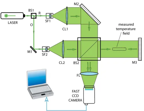
Figure 1: digital holographic setup with double sensitivity (BS-beam splitter, SF-spatial filter, H -hologram, CL - collimating objective, M – mirror, FL-focusing
lens, R-reference beam, O-object beam)
• Vít Lédl, TU Liberec, Studentská 2, 461 17, Liberec, Czech Republic, [email protected]
Tomáš Vít, IT CAS v.v.i., Dolejškova 1402/5, 182 00 Praha 8 , Czech Republic, [email protected] Roman Doleček, TU Liberec, Studentská 2, 461 17, Liberec, Czech Republic, [email protected] Pavel Psota, TU Liberec, Studentská 2, 461 17, Liberec, Czech Republic, [email protected]
Noncontact measuring methods are very suitable for temperature field distribution measurement. One of the biggest benefits of holographic interferometry over standard interferometry is its differential character. This in general means that imperfections in the beam paths do not influence the shape of obtained phase field. Digital holographic interferometry which has its own experimental difficulties is very attractive due to its direct retrieval of the interference phase after computer based evaluation of hologram [1]. Interference phase modulo 2π is obtained by subtracting two phase fields reconstructed from holograms captured in two different time instants. One is usually the reference and the second is the record after change of the measured property. In a measurement of a 2D temperature field distribution (synthetic jet’s properties as it impinges on the heated surface), DHI enables us to measure the temperature distribution in the area of interest. For measurement of transparent “phase objects”, a Mach-Zehnder holographic interferometric setup is commonly used. In this type of measurement the phase change is induced by the measured phenomenon is small, thus the sensitivity of the commonly applied interferometer is not sufficient.
We designed and developed an interferometric setup based on a Michelson interferometer. The light travels twice through measured phase object in this setup. The setup being twice as sensitive as the usual one is more complicated to adjust and is not so light efficient. The biggest portion of light energy is lost in the beam splitter BS2 (Fig.1).
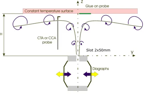
Figure 2: Experimental device and main dimensions (H is equal to 25mm in all experiments) for holographic interferometry and for hot-wire anemometry.
A 100-mW beam from frequency doubled (Nd3+:YAG) laser is divided by a polarizing beam splitter BS1 equipped with λ/2 plates. Outgoing beams are filtered by spatial filters SF and consequently collimated by lenses CL. Beam diameter is limited by apertures placed in front of the collimating objectives. Collimated, beam O enters beam splitter BS2. One part of the beam is reflected by the beam splitter while the second part travels through the measured object and perpendicularly impinges on mirror M2, where it is reflected and goes through the measured object once more. This is the key for increasing the sensitivity. Then once again in beam splitter BS2 part of the light is reflected towards the CCD camera and the second part continues in the direction of collimating objective
The digital hologram sequence is evaluated by in-house developed automatic software. Before the experiment can start, the first hologram is recorded. This hologram contains the data of the reference temperature distribution (in our case it was a picture of the measured area under the heated surface without the impinging jet). The phase difference obtained by comparison of the reference hologram and the measured holograms is dependent on the refractive index n of temperature field.
The distribution of temperature is our main concern in measuring of the synthetic jet. The value of temperature in the point (x, y) is determined by the effect it has on the refractive index in the same point. The key quantity here is the density ρ of the gas. Its relation to refractive index n is given by the Gladston-Dale equation:
ρ
K
n
−
1
=
, (1)where K is the Gladston-Dale constant, which is a property of the gas.
If the supposed smallest detectable change in phase is better than fractions of π, the resolution of the measuring system is better than 1 Kelvin [2]
2. EXPERIMENTAL SETUP
Figure 2 shows a schematic view of the actuator cavity and the configuration tested in this study. The actuator consists of a cavity which is equipped with an emitting slot (length L was equal to 50mm; width s was equal to 2.0 mm; corresponding characteristic diameter D was equal to 4 mm) and a pair of electrodynamically actuating diaphragms running in opposite directions (diameter DD was equal to 53 mm; originating from two
ARN-100-10/4 loudspeakers of diameter 94 mm, with nominal electrical resistance 4 Ω. The orifice is oriented vertically upwards to the exposed surface of area 0.13 x 0.13 m. The working fluid is air.
The exposed surface was an aluminum plate heated by an Omega KH-505/5-P Kapton insulated flexible heater. The temperature of the surface was measured by a K-type thermocouple which was placed on the exposed side of the wall and controlled by a connected PID regulator. The uncertainty of the set temperature of the wall was less than 0.2°C. To enable measurements in different positions the actuator was traversed in the y-direction under the wall.
Based on an analysis of the velocity field above the actuator [3] the distance between the surface and the slot H was set to 25mm in all of the experiments (which corresponds to H/D equal to 12.5). The input power of the loudspeakers was set to 10W, the temperature of the surface was 70°C and held constant during all experiments. The frequency of the oscillations was set to f = 1/T = 30Hz.
A Dantec 55P14 90°-wire probe operating in constant temperature mode was used to measure velocity magnitude. The sampling frequency and number of samples were 6 kHz and 8192, respectively.
3. RESULTS
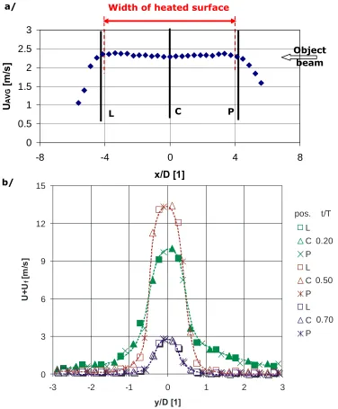
At first the two dimensionality of experimental was proved. The velocity profile at different positions z were measured at the center and at both ends (x=±17) of the slot. Results presented at Fig. 3 shows the velocity profile at x direction (Fig.3a) measured 35mm above the slot. Figure 3b compares the velocity profiles at the centre and both ends of the slot for different times (t/T=0.2; 0.5; 0.7). Presented results show that the velocity field above the slot should be considered as two dimensional.
Figure 3: Velocity field above the slot. a) profile of time averaged velocity measured at the centre of the slot (y=0) at z=35mm; b) comparison of temporal development of velocity profiles at the centre and at both ends of the
0 3 6 9 12 15
-3 -2 -1 0 1 2 3
y/D [1] U +U f [m /s ]
pos. t/T
C P L C P L C P 0.50 0.70 L 0.20 C b/ Object beam P
Width of heated surface
L a/
0
0.5
1
1.5
2
2.5
3
-8
-4
0
4
8
Figure 4: Experimental results showing the development of the temperature [°C] field between the slot and heated surface in different
In the figure 4 the development of the synthetic jet is visualized by digital holographic interferometry. Development of the temperature field in the vicinity of heated surface as well as the development of the jet of fluid which is leaving the slot is evident.
4. CONCLUSIONS
Digital holographic interferometry can record the whole (2D) temperature field at once with a frequency that is limited only by the parameters of the CCD camera used.
Unfortunately, the method integrates the phase change in the propagation direction of the ray on the entire path of the rays going through the measured area. This phenomenon can easily spoil the measurement as in each plane perpendicular to the direction of propagation the phase distribution can be different.
Digital holographic interferometry is very sensitive to noise and needs a sophisticated procedure and software to evaluate the results. The presented results show the need for implementing a phase averaging method into the evaluation software used.
5. ACKNOWLEDGEMENT
We gratefully acknowledge the support of the GAAS CR (No. IAA200760801).
6. REFERENCES
[1] Schnars U.; Jueptner W. Digital Holography. Berlin : Springer, 2005. 164 p. [2] Kreis, T. Handbook of Holographic Interferometry : Optical and Digital Methods.
Berlin : Wiley, 2004. 542 p.
[3] Trávníček Z., Vogel J., Vít T. and Maršík F., 2005, Flow field and mass transfer experimental and numerical studies of a synthetic impinging jet. In 4th International Conference on Heat Transfer, Fluid Mechanics and Thermodynamics – HEFAT2005, Cairo, Egypt, No. ZT4, 2005.
[4] Vít T., Lédl V.: Identification of the Temperature Field in Pulsatile Impinging
![Figure 4: Experimental results showing the development of the temperature [°C] field between the slot and heated surface in different time frames [t/T= a)0; b)125; c)250; d) 325; e) 500; f)625; g)750; h)875]](https://thumb-us.123doks.com/thumbv2/123dok_us/8084666.1349104/5.595.129.452.89.631/figure-experimental-results-showing-development-temperature-surface-different.webp)
