IP Camera User’s Manual Speco Technologies
IP Camera User’s Manual
(Version 1.2.1)IP-INTB1 & IP-INTB2
Network Bullet Cameras
IP-INTD3 & IP-INTD4
Network Dome Cameras
IP Camera User’s Manual Speco Technologies
IP-INTT5 & IP-T5
Network Traditional Cameras
Introduction
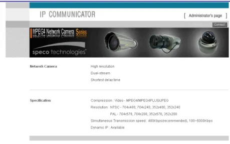
We appreciate your purchasing our IP Network Camera. This is a Network Camera with a built-in MPEG-4 CODEC and
Streaming Server. It uses an MPEG-4 CODEC as the Video Compression method and has a built-in Streaming Server which allows you to monitor and record real time images in remote places over the Internet.
Our IP cameras support both Static IP and Dynamic IP addresses and can change their Communication Ports, allowing several Network Cameras to be installed on one IP. Our IP cameras also permits you:
¾ To record an Event in your own FTP server installed in a remote location. ¾ To search / delete / down-load / replay the recorded video.
¾ Support various wireless devices such as Mobile Phone, PDA to see real time Video in Wireless Internet handset.
IP Camera User’s Manual Speco Technologies
Home Page : www.specotech.com Telephone : 631-957-8700 Fax : 631-957-9142
Address : 200 New Highway, Amityville, NY 11701
Appearance, function and specification may be changed without prior notification. Our company assumes no responsibility for visible or invisible loss resulted from changes in policy or products.
IP Camera User’s Manual Speco Technologies
Important Notes
The Network Camera may be damaged by electrical and physical shock
Do not try to disassemble the products. Contact or consult the distributor or Head Office for after sale service. There may be no Quality Assurance for the products disassembled arbitrarily.
Do not use these products to be connected with life related device like medical apparatus.
Do not touch the front lens of the camera. It is one of the most important parts of the camera.
IP Camera User’s Manual Speco Technologies
Contents
1.
FEATURE... 11
1.1.
P
ACKAGE...11
1.2.
D
IMENSION ANDC
AMERAF
EATURE... 12
1.2.1. Dimension... 12
1.2.2. Camera Feature (Not available with IP-T5)... 15
2.
INSTALL AND VIDEO CHECK ... 19
2.1.
I
NSTALLATION... 19
2.2.
V
IDEOC
HECK... 19
3.
BASIC SETTING ... 25
IP Camera User’s Manual Speco Technologies
3.2.
I
NSTALLATION WITHOUTIP
SHARING DEVICE(R
OUTER)
... 26
3.2.1. Static IP Setup... 26
3.2.2. Dynamic IP Setup... 31
3.3.
I
NSTALLATION WITHIP
S
HARINGD
EVICE(R
OUTER)
... 33
3.4.
C
AUTIONS... 37
4.
EXPERT SETTING... 41
4.1.
G
ENERALS
ETTING... 43
4.1.1. Title Setting... 43
4.1.2. Administrator’s ID and Password Change... 44
4.1.3. User Registration... 44
4.1.4. User List and Delete... 45
4.1.5. Skip Login (Automatic Monitoring)... 46
4.1.6. Time Zone Setting... 46
4.1.7. Set Download Route of Plug-in Type ActiveX... 47
4.1.8. Select Language... 47
4.2.
N
ETWORKS
ETTING... 48
4.3.
V
IDEOS
ETTING... 49
4.3.1. Video Setting... 494.4.
C
OLORS
ETTING... 51
4.5.
A
LARMS
ETTING... 51
4.5.1. Alarm Event Setting... 51
IP Camera User’s Manual Speco Technologies
4.6.
DIO
S
ETTING(
SUPPORT FORIP-INTT5/T5
ONLY)
... 54
4.7.
M
OTIONA
REAS
ETUP... 55
4.8.
C
AMERAS
ETTING(
SUPPORT FORPTZ
C
AMERA)
... 56
4.9.
H
OMEPAGEU
PDATE... 57
4.10.
F
IRMWAREU
PDATE... 58
4.10.1. Remote Upgrade... 58 4.10.2. System Re-booting... 614.11.
F
ACTORYR
ESET... 62
4.11.1. Reset Button... 624.11.2. In reset of Factory default... 62
5.
BASIC USE ... 64
5.1.
U
SE OFW
EBV
IEWER... 64
5.2.
U
SE OFOSD
(N
OT AVAILABLE WITHIP-T5)
... 67
5.2.1. Function... 68
5.2.2. OSD Menu Setting... 68
5.2.3. Operating Camera OSD Menu... 71
5.3.
U
SE OFIP
S
ETTINGU
TILITY... 92
5.4.
U
SE OFS
ERVICES
ERVER... 94
5.4.1. User Registration... 96
5.4.2. Camera Registration... 99
IP Camera User’s Manual Speco Technologies
5.4.4. Change of User’s Information... 102
5.4.5. Search Camera... 103
5.5.
S
EE ANDC
ONTROL OFS
TILLI
MAGE INM
OBILE ORPDA
...104
5.5.1. WAP2.0 (HTML)... 105
5.5.2. PDA(WinCE)... 107
5.6.
U
SE OFNVR
P
ROGRAM...109
5.6.1. Required Specification of PC and OS... 109
5.6.2. Supported O/S... 109
5.6.3. Refer the NVR User’s Manual in the CD-ROM... 109
6.
NETWORK ENVIRONMENT ... 112
IP Camera User’s Manual Speco Technologies
IP Camera User’s Manual Speco Technologies
IP Camera User’s Manual Speco Technologies
1.
Feature
1.1.
Package
Package of Products is composed of main body of product, Software CD (NVR Program, IP Utility, Product Manual, NVR Manual) , Quick Install Guide, Cross LAN Cable, Accessory, 12V DC Adapter. Please check before starting installation.
Software CD IP/Network Camera
Cross LAN Cable Accessory
Quick Install Guide
IP Camera User’s Manual Speco Technologies
1.2.
Dimension and Camera Features
1.2.1.
Dimensions
1) Bullet Camera
IP Camera User’s Manual Speco Technologies
2) Dome Camera
IP Camera User’s Manual Speco Technologies
1) Power Port: Power connection port (12 VDC) 2) VIDEO Port : Video Output Port (BNC)
3) LAN Port: LAN Connection Port ( Connect with LAN Cable for Local Network or Internet Viewing) 9 LINK: LED On (When the product connects with LAN Cable)
9 DATA: LED On (When user connects the product to the Network)
①
③
IP Camera User’s Manual Speco Technologies
1.2.2.
Camera Feature (Not available with IP-T5)
1) SLC ( Speco Light Compensation )
: When the image is in front of strong background lighting, your camera allows you to get a clear image.
2) Intensifier: 1/3 inch double density CCD and digital processor permit high quality pictures to be captured in very low light conditions.
3) High Resolution: The horizontal resolution of 540TV lines is achieved by using a SONY CCD having Double Speed 410,000 pixels.
4) Motion Detection: Video motion detection is built in to the camera.
5) OSD: Full on screen control of all critical features.
IP Camera User’s Manual Speco Technologies
7) Electronic Day/Night: Allows the camera to always remain in color or to switch into B/W at night.
IP Camera User’s Manual Speco Technologies
IP Camera User’s Manual Speco Technologies
IP Camera User’s Manual Speco Technologies
2.
Install and Check Video
2.1.
Installation
1) Connect the IP Camera to the PC by LAN cable (Crossover Cable) 2) Supply power to the camera using a 12 volt DC regulated power supply. 3) Wait approximately 2 minutes until the Link/LED light comes on.
2.2.
Video Check
Basic network setting value of the camera is to be: 9 IP Address: 192.168.1.7
9 Subnet Mask: 255.255.255.0 9 Gateway: 192.168.1.1
IP Camera User’s Manual Speco Technologies
Fig. 2―1 Network Setting of User PC
1) Set IP Address, Subnet Mask and Gate-way of User’s PC with 192.168.1.50, 255.255.255.0 and 192.168.1.1 as shown on [Fig. 2-1].
Fig. 2―2 Web Browser Input
2) Run Web Browser as [2-2] and input 192.168.1.7 in URL and click “Enter”, then [2-3] is shown. In case [2-3] does not appear, re-set Hardware (Reset Button in Camera) to reboot and run Web Browser, input 192.168.1.7 in URL line and click “Enter” .
IP Camera User’s Manual Speco Technologies
Fig. 2―3 THE CAMERA Main Page
3) Click “Connect” Button of [Fig. 2-3].
Fig. 2―4 User login
4) Input ID and Password on [Fig. 2-4] to see Video.
5) User’s Authority to see Video on THE CAMERA is as follows ;
IP Camera User’s Manual Speco Technologies
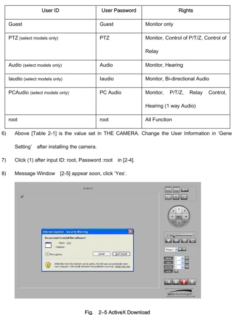
Table 2-1 User ID, Password, Rights
User ID User Password Rights
Guest Guest Monitor only
PTZ (select models only) PTZ Monitor, Control of P/T/Z, Control of Relay
Audio (select models only) Audio Monitor, Hearing
Iaudio (select models only) Iaudio Monitor, Bi-directional Audio PCAudio (select models only) PC Audio Monitor, P/T/Z, Relay Control,
Hearing (1 way Audio)
root root All Function
6) Above [Table 2-1] is the value set in THE CAMERA. Change the User Information in ‘General Setting’ after installing the camera.
7) Click (1) after input ID: root, Password :root in [2-4]. 8) Message Window [2-5] appear soon, click ‘Yes’.
IP Camera User’s Manual Speco Technologies
9) Upon installation, Web Viewer [Fig. 2-6] appears and the image of the Camera can be seen.
Fig. 2―6 Web Viewer
10) After checking proper operation as seen on [Pic 2-6], go onto the next Chapter (3) Basic Setting. 11) Refer to (5) Basic Use’ to see the details of how to use Web Viewer.
IP Camera User’s Manual Speco Technologies
IP Camera User’s Manual Speco Technologies
3.
Basic Setting
3.1.
Check Network and Installation Type
This Chapter is for basic setting of THE CAMERA. To install Hardware of the Network Camera, basic understanding of Networking is required. Please refer to Chapter 6 in case knowledge of Network Environment is required. There are 2 ways to install Hardware. One is to install THE CAMERA without IP sharing Device under Cable Modem or Leased Line, the other one is to install THE CAMERA under an IP sharing Device , which is required necessarily under PPPoE environment, and even under Leased Line or Cable Modem. The default IP Address of THE CAMERA is preset to 192.168.1.7 and Subnet Mask to 255.255.255.0 and Gateway to 192.168.1.1 in the factory. This explanation is based upon default value of the factory.
Caution 1 : Check Video before installation, on ‘2. Install and Video Check’. Caution 2 : In case using IP sharing Device, only Global IP is available.
Caution 3 : THE CAMERA does not support PPPoE. IP Sharing Device is required to connect to THE CAMERA under PPPoE.
Installation without IP sharing device -> For static IP, refer to ‘Static IP Setup’. -> For dynamic IP, refer to ’ Dynamic IP Setup’.
IP Camera User’s Manual Speco Technologies
-> Should set up with Static IP. Refer to ‘Installation with IP Sharing Device’.
3.2.
Installation without IP sharing device (Router)
3.2.1.
Static IP Setup
1) After checking Video in ‘Video Check’, go to the next step. 2) Connect THE CAMERA to PC with LAN Cable (Crossover Cable).
3) Cable connection and Network Setup should be same as shown in ‘2. Install and Video Check’.
4) Run Web Browser and input 192.168.1.7 in URL and click ‘Enter’, then [Fig. 3-1] will appear.
IP Camera User’s Manual Speco Technologies
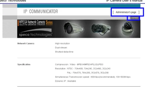
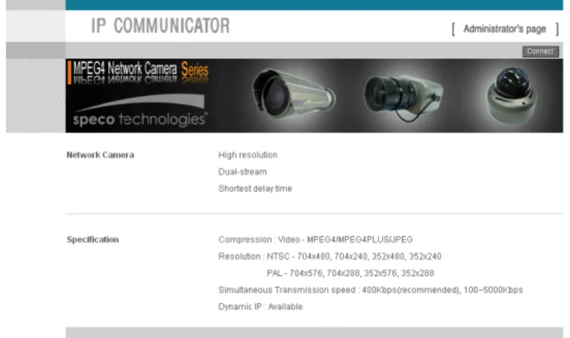
Fig. 3―1 Main Page of THE CAMERA Network Camera
5) Click ‘Administrator’s Page’ of [Fig. 3-1], then Browser shows [3-2] Log-in Page.
Fig. 3―2 Administrator Page Log-in
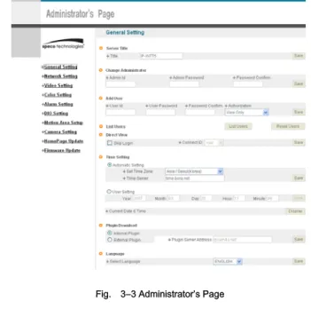
6) Put ‘admin’ in ID and Password line, click ‘Login’, then [3-3] ‘Administrator's Page’ will be shown. (ID, Password of THE CAMERA is preset as admin/admin in Administrator’s Page. Change Administrator’s ID and Password in General Setting of ‘4. Expert Setting’
IP Camera User’s Manual Speco Technologies
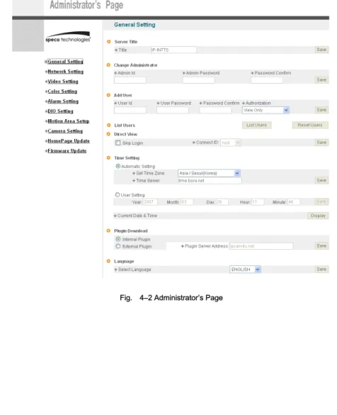
Fig. 3―3 Administrator’s Page
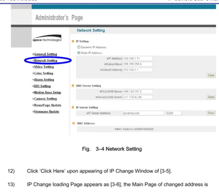
7) Click “Network Setting’ in left menu on [3-3], [3-4] appears.
8) Click ‘Static IP Address’ in ‘IP Setting’ of [3-4], and input IP Address, Subnet Mask, Default Gateway according to Network environment to connected THE CAMERA to. 9) For setting of ‘DNS Server’, input DNS Address to fit with Network Environment to set.
Use DNS value normally set in PC. 10) DNS Address must be entered.
IP Camera User’s Manual Speco Technologies
Fig. 3―4 Network Setting
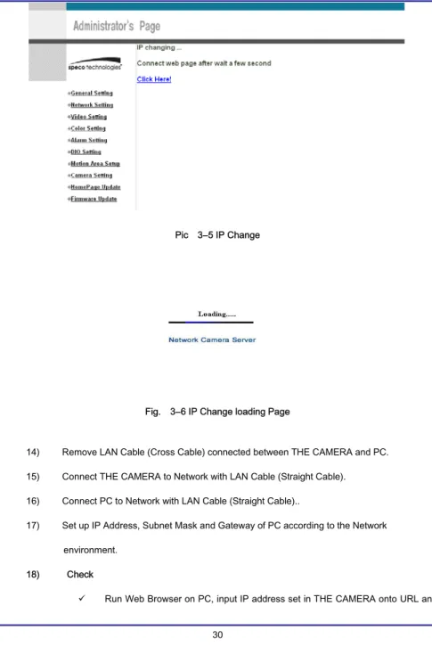
12) Click ‘Click Here’ upon appearing of IP Change Window of [3-5].
13) IP Change loading Page appears as [3-6], the Main Page of changed address is connected. (Note: You may not find the main page of changed address under Cross Cable connection, but IP has been changed.)
IP Camera User’s Manual Speco Technologies
Pic 3―5 IP Change
Fig. 3―6 IP Change loading Page
14) Remove LAN Cable (Cross Cable) connected between THE CAMERA and PC. 15) Connect THE CAMERA to Network with LAN Cable (Straight Cable).
16) Connect PC to Network with LAN Cable (Straight Cable)..
17) Set up IP Address, Subnet Mask and Gateway of PC according to the Network environment.
18) Check
IP Camera User’s Manual Speco Technologies
click ‘Enter’,
9 Check if IP Setting is correct or not, referring to ‘Video Check’ 9 If Video is seen, THE CAMERA has been correctly set up.
9 If Video is not seen, check whether there may be a conflict of IP in the Network, and re-check the set value of Network environment of THE CAMERA, and Network environment of User’s PC.
3.2.2.
Dynamic IP Setup
9 Do not set up Dynamic IP in the camera except as a direct connection
of Cable Modem supporting Dynamic IP with the camera.
9 Reset, in case IP has not been allocated to THE CAMERA in Dynamic
IP Setting, to go to Initial Value and try again. 1) After checking Video in ‘Video Check’, then go to the next step. 2) Connect THE CAMERA and LAN Cable (Cross Cable)
3) Cable Connection and Network Setting should be done same as per ‘2. Install and Video Check’.
4) Go to Network Setting Page of Administrator’s Page as per 4), 5), 6), 7) of ‘Static IP Setup’.
IP Camera User’s Manual Speco Technologies
Fig. 3―7 Network Setting
5) Click on ‘Dynamic IP Address’ in ‘IP Setting’. 6) Click ‘Save’ Button.
7) Upon completion of setting, close the Web Page and find IP of THE CAMERA in ‘IP Utility’ program provided with Proprietary Viewer (see ‘5. Basic Use’)
8) If the IP is found, THE CAMERA has been given an IP. But in case the IP is not found, do a re-set of [2-1] to go to initial value because it has not been given an IP, then re-start the IP Setting. Once THE CAMERA has an IP, remove the LAN Cable (Crossover Cable) connected between THE CAMERA and the PC.
9) Connect THE CAMERA to the Network with LAN Cable (Straight Cable). 10) Connect PC to Network with LAN Cable (Straight Cable).
11) Set IP address of PC, Subnet Mask and Gateway properly according to the Network Environment.
IP Camera User’s Manual Speco Technologies
After registration of THE CAMERA in Service Server (refer to ‘Use of Service Server’ of ‘ 5. Basic Use’,
connect to THE CAMERA by Domain Name (Server Name) allocated to THE CAMERA. For example, run Web Browser and input Domain Name allocated to THE CAMERA in URL. In http://IPXXXXX.ipcam4u.net, ‘IPXXXXX’ is to be Name of Server registered in Service Server by user.
If the initial page is shown as [3-8], check Video of THE CAMERA referring to ‘2. Install and Video Check’. If Video is seen, set up is properly done.
Fig. 3―8 Initial Page of THE CAMERA
3.3.
Installation with IP Sharing Device (Router)
1) After checking Video in ‘2. Install and Video Check’, then go to the next step. 2) Connect THE CAMERA and PC with LAN Cable (Crossover Cable).
IP Camera User’s Manual Speco Technologies
Check’.
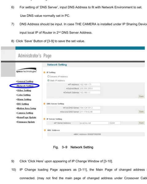
4) Go to Network Setting Page of Administrator’s Page as per 4), 5), 6), 7) of ‘Static IP Setup’. 5) Click ‘Static IP Address’ in ‘IP Setting’ of [3-9], and input IP Address, Subnet Mask, Default
Gateway according to Network environment to connected THE CAMERA to.
6) For setting of ‘DNS Server’, input DNS Address to fit with Network Environment to set. Use DNS value normally set in PC.
7) DNS Address should be input. In case THE CAMERA is installed under IP Sharing Device, input local IP of Router in 2nd DNS Server Address.
8) Click ‘Save’ Button of [3-9] to save the set value.
Fig. 3―9 Network Setting
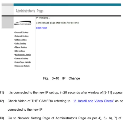
9) Click ‘Click Here’ upon appearing of IP Change Window of [3-10].
10) IP Change loading Page appears as [3-11], the Main Page of changed address is connected. (may not find the main page of changed address under Crossover Cable
IP Camera User’s Manual Speco Technologies
connection, but IP has been changed.)
Fig. 3―10 IP Change
11) It is connected to the new IP set up, in 20 seconds after window of [3-11] appears. 12) Check Video of THE CAMERA referring to ‘2. Install and Video Check’ as soon as it is
connected to the new IP.
13) Go to Network Setting Page of Administrator’s Page as per 4), 5), 6), 7) of ‘Static IP Setup’.
IP Camera User’s Manual Speco Technologies
Fig. 3―12 Port Setting
14) Set Port in Port Setting Page of [3-12]. It is required to set each different Port for many THE CAMERA Network Cameras under 1 Router.
15) Click ‘Save’ Button to save set value.
16) Remove LAN Cable (Crossover Cable) connected between THE CAMERA and PC. 17) Connect THE CAMERA to Network with LAN Cable (Straight Cable).
18) Connect PC to Network with LAN Cable (Straight Cable).
19) Port-Forward the port designated to use THE CAMERA, in IP Sharing Device. Refer to manual of IP Sharing Device for details.
20) Check 1 (local check)
Run Web Browser and input IP address of THE CAMERA in URL and click ‘Enter’. If you changed Web Server Port, you must input ‘http://IP Address:Port Number’. For example, if you set IP address of THE CAMERA to 192.168.10.88 and changed Web Server port to 81, you must input http://192.168.10.88:81.
IP Camera User’s Manual Speco Technologies
Fig. 3―13 Main Page of THE CAMERA
After [3-13] appears, check Video of THE CAMERA referring to‘2. Install and Video Check’. 21) Check 2 (Check from outside)
After registration of THE CAMERA in Service Server (refer to ‘‘Use of Service Server’ of ‘‘ 5. Basic Use’,
connect to THE CAMERA by Domain Name (Server Name) allocated to THE CAMERA. For example, run Web Browser and input Domain Name allocated to THE CAMERA in URL. In http://IPINTB1.ipcam4u.net , ‘IPINTB1’ is to be Name of Server registered in Service Server by user.
If the initial page is shown, check Video of THE CAMERA referring to ‘2. Install and Video Check’. If Video is seen, set up is properly done.
3.4.
Cautions
IP Camera User’s Manual Speco Technologies
the port of THE CAMERA, then it will work properly. The port being used by THE CAMERA can be checked
on ‘Port Setting’ of ‘Network Setting’ of ‘Administrator’s Page’. Port of THE CAMERA on ex-factory is set default as follows ;
¾ Web Connection Port: Port 80 TCP
¾ Authentication and Control Port: Port 9000 TCP ¾ Video Streaming Port: Port 9001 TCP
¾ Motion Detection Control Port : Port 9005 TCP
IP Camera User’s Manual Speco Technologies
IP Camera User’s Manual Speco Technologies
IP Camera User’s Manual Speco Technologies
4.
Expert Setting
After registration of THE CAMERA in Service Server (refer to ‘Use of Service Server’ of ‘‘ 5. Basic Use’’, connect to THE CAMERA by Domain Name (Server Name) allocated to THE CAMERA. (For example, run Web Browser and input Domain Name allocated to THE CAMERA in URL. In http://ipcam4u.net, ‘THE CAMERA’ is to be Name of Server registered in Service Server by user)
Click ‘Administrator’s Page’ on Initial Page of THE CAMERA, login Page of [4-1] appears. Put ‘admin’ in ID and Password line, click ‘Login’, then [4-2] ‘Administrator's Page’ will be shown. (ID, Password of THE CAMERA is preset as admin/admin in Administrator’s Page. Change
Administrator’s ID and Password in General Setting of ‘4. Expert Setting’. )
IP Camera User’s Manual Speco Technologies
IP Camera User’s Manual Speco Technologies
4.1.
General Setting
Fig. 4―3 General Setting
4.1.1.
Title Setting
Fig. 4―4 Title Setting
IP Camera User’s Manual Speco Technologies
Click ‘Save’ Button to save title after input name.
4.1.2.
Administrator’s ID and Password Change
※ Cautions : Change Administrator’s ID and Password and do not disclose the information to others. Administrator’s ID and Password should be English, within 20 characters, without space.
Click ‘Save’ Button to save the changed value after change Administrator’s ID and Password.
Fig. 4―5 Administrator’s ID and Password Change
Remember Administrator’s ID and Password. In case of forgetting Administrator’s ID and
Password, click the camera’s ‘reset’ button to return to the initial value, and change Administrator’s ID and Password.
4.1.3.
User Registration
This is to register an account of a user who can monitor and control Video of THE CAMERA. Administrator’s ID and Password should be English, within 20 characters, without space. Assign the authority to users and click ‘Save’ button. Maximum number of users to be registered is 100 people.
¾ View Only: Monitoring only.
¾ PTZ + Control: Monitoring, Control of P/T/Z of Camera and Relay. (select models only) ¾ Audio: Monitoring, and hearing Audio of Server. (select models only)
¾ Interactive Audio: Monitoring, Two-way Audio Communication with Camera Server (select models only)
IP Camera User’s Manual Speco Technologies
¾ PTZ + Control + Audio: Monitoring, Control of P/T/Z of Camera and Relay, Hearing Audio of Camera Server. (select models only)
¾ All : Monitoring, Control of Camera P/T/Z and Relay, two-way Audio Communication with Camera Server, (Preset available)
Fig. 4―6 User Registration
4.1.4.
User List and Delete
Fig. 4―7 User List
User list is available on clicking ‘List Users’ on [4-7], to check list and delete user ID in [4-8]. User ID ‘guest’, ‘PTZ’, ‘audio’, ‘Iaudio’, ‘PC Audio’, ‘root’ has be pre-registered as basic user ID on ex-factory.
IP Camera User’s Manual Speco Technologies
4.1.5.
Skip Login (Automatic Monitoring)
Fig. 4―9 Skip Login
Tick on ‘Skip Login’ of [4-9], and click ‘Connect ID’ and save the value, then Web Viewer will
appear automatically and Video of Camera can be seen upon connection to Home Page of THE CAMERA.
Save ‘Connect ID’ according to user authority. If you don’t tick on ‘Skip Login’, it is available to connect to THE CAMERA Home Page but you can see Video of Camera. In this case, input user ID and Password for connection to see Video of Camera.
4.1.6.
Time Zone Setting
This is to set Time zone of location where THE CAMERA is to be installed, to set up local time in case of monitoring from different time zone area. Select one of time zone in ‘Set Time Zone’ and save.
Fig. 4―10 Time Zone
IP Camera User’s Manual Speco Technologies
Fig. 4―11 Current Time View
In case THE CAMERA does not keep correct time, click ‘Update’ Button to get new time information from set time zone.
4.1.7.
Set Download Route of Plug-in Type ActiveX
This is to set how to download ActiveX of Web Viewer, locally or from outer Server designated. In case setting as local download, it has a merit to use in private network without Internet. In case of setting as download from outside, it has a merit to download the updated Active X of
Web Viewer automatically.
Fig. 4―12 Plug-in Download Route
4.1.8.
Select Language
This is to select language to be displayed in all Web Pages such as Administrator’s Page, Web Viewer and Main Page of THE CAMERA.
IP Camera User’s Manual Speco Technologies
Fig. 4―13 Select Language
It supports both English and Japanese. Click ‘Save’ Button to save the set value after select the Language. Input ID and Password to connect Administrator’s Page, and go to ‘Home Page Update’->’Default Home Page Setting’->’Default’, and change the main Page and Login Page of THE CAMERA to the selected language.
4.2.
Network Setting
This is to set Network to use THE CAMERA. Set Network to fit user’s network environment in ‘3. Basic Setting ’. Change Network information to fit environment for THE CAMERA to be installed in.
IP Camera User’s Manual Speco Technologies
4.3.
Video Setting
Fig. 4―14 Video Setting
4.3.1.
Video Setting
Select and tick on the Channel to use, input Video format (NTSC or PAL), Compressed resolution, Bit rate, Frame rate, Key frame. Video setting can be done automatically by pressing ‘High’, ‘Normal’, ‘Low’ according to the Network Speed at which THE CAMERA is installed.
IP Camera User’s Manual Speco Technologies
Fig. 4―15 Video Setting
IP Camera User’s Manual Speco Technologies
4.4.
Color Setting
This is to adjust color of channel.
Fig. 4―17 Display Color Setting
Upon adjustment of color on [4-17], then click ‘Save’ to save the setting value. In case to return to default, click ‘Default’ to go to default. Even in this case, it is required to click ‘Save’ Button to save the setting value.
4.5.
Alarm Setting
4.5.1.
Alarm Event Setting
IP Camera User’s Manual Speco Technologies
‘Enable’ in ‘Alarm’.
Fig. 4―18 Alarm Setting
Designate condition to drive Event in ‘Alarm Condition’, such as Sensor Event, Motion detection Event or Sensor + Motion detection Event, If Sensor Event is selected, make Sensor settings
Upon event situation after setting on ’Enable’ in ‘Alarm’ of ‘Alarm Event’, Event is to be transmitted to user’s Viewer and inform detection of Event, with flickering on screen and alarm sound. (refer to 5. Basic Use).
To use SMS Service and E-mail transmitting Event to Alarm Server, go to ‘Alarm Style’-> ‘Alarm Server’ and input Domain Name of Alarm Server (‘Alarm Server’ is defaulted as Ipcam4u.net).
To send the recorded video to FTP Server upon alarm event, go to ‘Alarm Style’-> ‘FTP’ and input FTP Server Address, Directory, User IP and Password, FTP Directory (mandatory). Make the user’s directory in ftp root of User’s FTP Server to get recorded files to be transmitted. Click ‘Save’ Button to save setting.
IP Camera User’s Manual Speco Technologies
Alarm Server (refer to ‘‘Use of Service Server’ in ‘ 5. Basic Use)
4.5.2.
Alarm Event Test
Click ‘Test’ of [4-18], THE CAMERA will work as if Alarm has happened. In case selected ‘Alarm Style ->’Alarm Server’, Event is to be notified to Alarm Server and is to recorded into the recorded file (10 seconds before and 50 seconds after Event), and to be sent to Alarm Server.
In case selected to use user FTP Server, the recorded file (10 seconds before and 50 seconds after Event) is to be saved in FTP Server. It may take some time for Alarm Message to get to user’s Mobile Phone or by E-mail, in some cases. If THE CAMERA has been registered in Service Server, it is available to check the details of Event and also change the Alarm Message of E-mail and Mobile Phone to be sent upon Event, in Alarm Server Homepage (Ipcam4u.net). Refer to ‘Use of Service Server’ in ‘ 5. Basic Use’ for details.
IP Camera User’s Manual Speco Technologies
4.6.
DIO Setting (support for IP-INTT5/T5 only)
Fig. 4―19 DIO Setting
Tick on sensor to use and select type of sensor to use.
9 Sensor Type : designate type of sensor, NC, NO. Designate name of sensor to use.
4 conditions are selectable for Relay. Relay name is to be input. 9 Disable: Relay is not active
9 Remote Control: to control Relay through Internet using Viewer
9 Local Control: Relay is on during ‘Duration’ time upon Event on Sensor, then is off. 9 Remote & Local Control: Control Relay through Internet using Viewer. To be ON
IP Camera User’s Manual Speco Technologies
4.7.
Motion Area Setup
9 (1) Motion Area Set: Press the set button. Place the mouse curser on this area and drag it out to the desired area.
9 (2) Area Clear: Cancel the former area established.
9 (3) Save: Please wait for 3 to 5 sec. while camera save the present setting information by itself.
IP Camera User’s Manual Speco Technologies
4.8.
Camera Setting(support for PTZ Camera)
Fig. 4-20 Camera Setting
It is available to pre-set Pan/Tilt/Zoom Cameras.
Preset Setting is available up to 20, but may be less than 20 for some model of Camera. 9 (1) OSD Menu: to activate OSD Menu.
9 (2) Preset No: to select the Preset Number to set up.
9 (3) Preset SET: ‘SET’ button is to set the current coordinate as preset location with name recorded by user. In 3 seconds after pushing ‘SET’ button, the Preset coordinate is to be set. Don’t move Camera during the time (about 3 seconds).
9 (4) Preset Move: to move to the selected preset number. 9 (5) Tour No: to select the Tour Number to set up.
IP Camera User’s Manual Speco Technologies
9 (6) Tour Move: to move to the selected preset number. 9 (7) Pattern No: to select the Pattern Number to set up. 9 (8) Pattern Move: to move to the selected Pattern number.
9 (9): Adjustment of Pan/Tilt/Zoom/Speed/Focus: to move to the location to preset by adjusting Pan/Tilt/Zoom/Focus.
4.9.
Homepage Update
Fig. 4―21 Homepage Update
Homepage Update function is for user to upload the main page of THE CAMERA onto user’s Homepage. User’s Homepage is composed of 3 files, index.html, top.htm, main.htm. The file for user to use is main.htm. After making Web Page (main.htm) and save it as file name of main.htm, upload by the function of ‘Homepage Update’, then main.htm page is to be the 1st main page of THE CAMERA. (Image file is not uploaded in THE CAMERA.) User Homepage can’t exceed 300Kbyte.
If user wants to re-make user’s homepage into Homepage provided complimentarily, click ‘Default HomePage Upload’.
IP Camera User’s Manual Speco Technologies
4.10.
Firmware Update
In case firmware is upgraded in the future, Upgrade Server (http://ipcam4u.net) will automatically upgrade Firmware of THE CAMERA. Upgrade is only supported through Network. Information on latest version of THE CAMERA will be posted in Data Room of Speco Technologies Homepage. (http://www.specotech.com)
4.10.1.
Remote Upgrade
Fig. 4―22 Firmware Update
Address of ‘Update Server Address’ in [4-22] is set as ‘ipcam4u.net’.
Check ‘Current Software Version’ in ‘Current Version’ of [4-22] and go ahead with update if current version is lower than latest version. Upon clicking ‘Update’ button in [4-22] ‘Remote Update’, [4-23] will appear.
IP Camera User’s Manual Speco Technologies
Fig. 4―23 Firmware Update
THE CAMERA will be automatically upgraded upon clicking ‘Download’ button of [4-23] after connecting to Upgrade Server and checking version.
Fig. 4―24 Firmware Download
‘Downloading’ message will be shown until completion of Update as [4-24] (it may take time according to Network situation). Upon completion of upgrade, there appears message showing upgrade result.
[4-25] is the message showing that upgrade has been correctly done. Click ‘Restart’ in ‘System Restart’ to restart System of THE CAMERA.
IP Camera User’s Manual Speco Technologies
Fig. 4―25 Completion of Upgrade
If [4-26] is displayed as below, this means that THE CAMERA has been upgraded to the latest Version, there is no need to update any more.
Fig. 4―26 Check of Upgrade Version
If user found [4-27], there is a error in connection to Upgrade Server, re-check Internet Connection or re-check DNS Server Address in ‘3. Basic Setting’ and try to upgrade again. If user keep finding [4-27] or can’t upgrade, contact head office of Speco Technologies
IP Camera User’s Manual Speco Technologies
4.10.2.
System Re-booting
This is the function to re-boot Inner Software of THE CAMERA. Click ‘Restart’ on [4-41] ‘System Restart’ to reboot all inner program of THE CAMERA.
IP Camera User’s Manual Speco Technologies
4.11.
Factory Reset
4.11.1.
Reset Button
Press reset button for 1sec to be operated.(Red Circle)
Fig. 4―28 Factory reset button
4.11.2.
In reset of Factory default
9 Changed to [192.168.1.7] of IP Address.
Bullet Camera Traditional Camera
IP Camera User’s Manual Speco Technologies
9 Changed to [192.168.1.1] of Gateway. 9 Changed the Server Login Port No. to “Default”. 9 Changed Web Admin Password to initial data. 9 Initialized DNS Number.
IP Camera User’s Manual Speco Technologies
5.
Basic Use
5.1.
Use of Web Viewer
Fig. 5―1 Web Viewer
Table. 5-1 Definition of Web Viewer Button Function
Display Screen reduced by 50%.
Display Screen at 100%. Double-clicking mouse on enlarged screen has the same function.
Enlarge Video of a channel to 640 x 480. Double-clicking in a selected channel has the same function.
IP Camera User’s Manual Speco Technologies
Capture a selected channel into a BMP file
Select Relay to control. Relay name is taken from the Camera Server Relay ON
Relay OFF
Select Preset to control Select Tour to control Select Pattern to control
Move to the selected Preset/Tour/Pattern.
Preset Tour. Move to preset location in regular sequence from No. 1 up to 200. Move to next one after 5 seconds pause on a preset location.
Display Camera Menu functions of Intensifier Cameras
While pressing the mouse in the direction, P/T, Camera moves. Un-pressing mouse makes Camera stop. Keep Un-pressing on screen to a point makes the Camera move to the direction, un-pressing mouse makes Camera stop.
Control Speed of Pan/Tilt. ‘S’ makes speed of P/T slow. ‘F’ makes speed of P/T fast. (for speed dome Cameras)
Zoom In. Zoom Out. Focus Near Focus Far
IP Camera User’s Manual Speco Technologies
Flickering on Screen and Alarm Sound
Upon detection of a motion event, the border around the associated camera picture will flash and an alarm will beep. To stop the sound, double-click on the flashing screen.
Table 5-2 Definition of Web Viewer Key Board
②
9 ‘space ’Key’9 Enlarge / reduce Screen
③
9 Number Key’9 Preset Move Function,
9 The Number represents the Preset Number 9 20 Preset is controlled by Key Board 9 Key Board 1 ~ 0 : Preset 1 ~ Preset 10 9 Key Board q ~ p : Preset 11 ~ Preset 20
④
9 ‘Direction Key’①
⑥
⑤
④
③
②
③
⑥
IP Camera User’s Manual Speco Technologies
9 Pan/Tilt of Camera
9 Pressing on the direction Key makes Camera move to the direction. Un-pressing stops moving.
⑤
9 Same function as
⑥
9 Zoom-in, Zoom-out Function9 ‘+’ is Zoom In, Pressing the key makes doing the function. Un-pressing stops the function
9 ‘-‘ is Zoom Out, Pressing the key makes doing the function. Un-pressing stops the function.
5.2.
Use of OSD (Not available with IP-T5)
The OSD menu of this camera can be controlled by Web Viewer. Please refer to the ‘1.2.2 Camera Feature’ for OSD function.
IP Camera User’s Manual Speco Technologies
5.2.1.
Function
5.2.2.
OSD Menu Setting
When you control the OSD by using the joystick on the camera, refer to the following (select models only)
SETUP MENU LENS option
●DC ●MANUAL SHUTTER
●OFF ●F/L ●MANUAL
WHITE BALANCE
SLC
OFF LOW MIDDLE HIGH
AUTO GAIN ●OFF ●ON REDUCE NOISE
●OFF ●LOW ●MIDDLE ●HIGH INTENSIFIER
●AUTO ●OFF
NEXT PAGE
●CAMERA TITLE ●COLOR ●SYNC ●PRIVACY ●MIRROR
IP Camera User’s Manual Speco Technologies
When you control by the five keys on the Webviewer GUI refer to the following
R I G H DOWN UP SETUP L E F
IP Camera User’s Manual Speco Technologies
IP Camera User’s Manual Speco Technologies
5.2.3.
Operating Camera OSD Menu
SET UP menu is displayed on the monitor screen. 1. Press the SET button to access the SETUP mode.
Each time you press the UP or DOWN button, the arrow indicator moves up or down.
2. Select the desired feature using the UP or DOWN button.
If you press RIGHT or LEFT button, it appears available status. Press the button when gets desired feature
3. Change the status of the selected feature using the LEFT or RIGHT b tt
4. When completed, move the arrow indicator to ‘EXIT" and press the SET button
Notes
You can access submenu using SET button. For the mode with ’---‘ you may not access submenu
IP Camera User’s Manual Speco Technologies
IP Camera User’s Manual Speco Technologies
1) Setting up the LENS
Select the lens pressing the RIGHT button.
① On the SETUP menu screen, move the arrow indicator to the lens
i th UP DOWN b tt
IP Camera User’s Manual Speco Technologies
▶When DC LENS selected, press SET button to control the BRIGHTNESS.
IP Camera User’s Manual Speco Technologies
① Press the SET button to display the setup menu and move the arrow indicator to ‘SHUTTER’ using the UP or DOWN button.
▶ OFF : Deactivation
▶ FLK(1/100) : Flicker mode
(When WDR is on the image can flicker a little ) 1) Shutter status and speed control
IP Camera User’s Manual Speco Technologies
▶MANUAL : When setting shutter speed manually. (Only for LENS mode)
You can select speed from ‘1/60’ to
IP Camera User’s Manual Speco Technologies
▶ESC : You can control the BRIGHTNESS.
IP Camera User’s Manual Speco Technologies ▶HIGH ▶MIDDLE ▶LOW ▶OFF
① Press the SET button to display the SETUP menu and move the arrow indicator to ‘BACKLIGHT’ using the UP or DOWN button.
② SET‘BACKLIGHT’to the desired mode using the LEFT or RIGHT button. 3) SLC (Speco Light Compensation) - BACKLIGHT
A built-in SR chip provides intelligent light level control to overcome severe Backlight conditions.
IP Camera User’s Manual Speco Technologies
① Press the SET button to display the SETUP menu and move the arrow indicator to ‘AGC’ using the UP or DOWN button.
② SET‘BACKLIGHT’to the desired mode using the LEFT or RIGHT button 3) AUTO GAIN CONTROL (AGC)
AGC is to get bright picture. Higher GAIN level, getting brighter screen. But you can get noise increase
▶ON ▶OFF
IP Camera User’s Manual Speco Technologies
① Press the SET button to display the SETUP menu and move the arrow indicator to ‘WHITE BALANCE’ using the UP or DOWN button. ② Set‘WHITE BAL.’to the desired mode using LEFT or RIGHT button. 5) WHITE BALANCE (WHITE BAL.)
For color control on the screen, use‘WHITE BALANCE’function.
▶ ATW (Auto Tracking White Balance)
: When color temperature is 2400~12000K, select this mode. (ex. A fluorescent lamp, outdoor)
▶ AWC (Auto White Balance Control)
: The white balance is automatically adjusted in a specific environment. In order to obtain the best result, press the set button while the camera focuses on white paper. If the environment including the light source is
IP Camera User’s Manual Speco Technologies
▶MANUAL : To fine adjust, select the Manual mode. You can increase or decrease the red or blue factor while monitoring the difference on the screen. Set to ‘MANUAL’ mode and press the SET button. Increase or decrease the value for RED(R-Gain) and BLUE(B-Gain), watching the color of the picture and press the SET button when you obtain the best color
Proper White Balance may not be obtained under the following conditions in these cases select the AWC mode.
When the scene contains mostly high color temperature object, such as a blue sky or sunset.
When the scene is dim.
IP Camera User’s Manual Speco Technologies
① Press the SET button to display the SETUP menu and move the arrow indicator to ‘DNR’ using the UP or DOWN button. ② SET ‘DNR’ to the desired mode using the LEFT or RIGHT button.
▶HIGH : High reduction of the noise ▶MIDDLE : Middle reduction of the noise ▶LOW : Low reduction of the noise ▶OFF : Deactivation
Notes
6) Digital Noise Reduction (Dynamic Noise Reduction) DNR is to reduce the noise on the screen.
If you change the ‘GAIN’ menu from AGC-L to AGC-H sensitivity is increased as well as noise on the screen.
IP Camera User’s Manual Speco Technologies
① Press the SET button to display the SETUP menu and move the arrow indicator to ‘Intensifier’ using the UP or DOWN button. ② SET ‘Intensifier’ to the desired mode using the LEFT or RIGHT button.
Notes
▶AUTO : When your camera is under night or low-lighting level, select this mode.
7) INTENSIFIER
Allows you to get clear images with this function under night l li ht diti
If you press SETUP button at ‘AUTO’ menu, you can control the lowlight action maximum magnifications.(X2~X128)
Increasing the amount of Intensification results in brighter pictures Under low light conditions, and may increase image lag. Increasing the amount of intensification may cause image noise
IP Camera User’s Manual Speco Technologies
8) NEXT PAGE
If the CAMERA ID feature is set to ‘OFF’, the name will not displayed in the monitor.
Notes
① Press the SET button to display the SETUP menu and move the arrow indicator to ‘CAMERA TITLE’ using the UP or DOWN button. ② SET‘ON’using the LEFT or RIGHT button
① Press the SET button to display the SETUP menu and move the arrow indicator to ‘Intensifier’ using the UP or DOWN button. ② SET‘Intensifier’to the desired mode using the LEFT or RIGHT button
IP Camera User’s Manual Speco Technologies
If the CAMERA TITLE feature is set to ‘OFF’, the name will not displayed in the monitor.
After erasing the character from right to left correct the character again
Notes
③ Press SET button to access the SETUP mode. ④ You can enter up to 15 characters.
a. Move the cursor to character-enter location by using the LEFT or RIGHT button.
b. Select the desired character by using the UP or DOWN button. c. Press SET button to confirm the blinking character. The first character is saved and the cursor in the bottom of the screen moves to the next position.
IP Camera User’s Manual Speco Technologies
B) COLOR
Y h l d B/W d l t i ll (OPTION)
OSD Key may not work for 3 seconds when the COLOR/ BW mode is changed.
Notes
▶ ON : color mode
▶ AUTO : generally color mode, B/W mode in low luminance. ▶ OFF : B/W mode
IP Camera User’s Manual Speco Technologies
① Press the SET button to display the setup menu and move the arrow indicator to ‘SYNC’ using the UP and DOWN button.
② SET to the desired mode using the LEFT or RIGHT button. C) SYNC
Line Lock is only available in the 24 volt AC mode of operation.
In 12 volts DC, the SYNC menu is always in the ‘INTERNAL’ mode.
Notes
Two SYNCHRONIZATION modes are available… INTERNAL and EXTERNAL LINE-LOCK. In LINE-LOCK mode, the camera syncs to the 60 Hz phase.
▶ INT : Internal synchronization
▶ L/L : If you choose ‘L/L’, you can adjust the desired phase. - Press the SET button.
IP Camera User’s Manual Speco Technologies
IP Camera User’s Manual Speco Technologies
① Press the SET button to display the setup menu and move the arrow indicator to ‘PRIVACY’ using the UP and DOWN button.
② SET ‘PRIVACY’ to the desired mode using the LEFT or RIGHT button. D) PRIVACY
▶OFF : Deactivation
▶ON : PRIVACY mode activated -Press the SET button.
-Move the arrow indicator to area you want to mask. -Set ‘ON’ using LEFT or RIGHT button.
-Press the SET button and then set the area’s bounds with the method like MOTION DET. set
IP Camera User’s Manual Speco Technologies
① Press the SET button to display the setup menu and move the arrow indicator to ‘REVERSE’ using the UP and DOWN button.
② SET‘REVERSE’to the desired mode using the LEFT or RIGHT button E) REVERSE
▶OFF : Deactivation
IP Camera User’s Manual Speco Technologies
① Press the SET button to display the setup menu and move the arrow indicator to ‘DETAIL’ using the UP and DOWN button.
② SET‘DETAIL’to the desired mode using the LEFT or RIGHT button F) DETAIL
▶OFF : Deactivation
▶ON : DETAIL control mode (level 0~31)
When the level is up, the sharpness will increase. Control this level to get your best picture quality. If the level is too high, you can get an unnatural image
IP Camera User’s Manual Speco Technologies
5.3.
Use of IP Setting Utility
Upon running IP Setting Utility, the following program is to be displayed.
Fig. 5―2 IP Find
Click ‘IP Find’ Button to find IP of THE CAMERA on local Network. G) DEFAULT
: Use to reset your camera to FACTORY DEFAULT SETTING.
H) PAGE1
IP Camera User’s Manual Speco Technologies
Fig. 5―3 Display IP
The following window shows list of IP along with Web Server Port Number and Model Name of THE CAMERA. Click ‘IP Find’ Button to find IP of THE CAMERA on local Network.
Fig. 5―4 IP Check
IP Camera User’s Manual Speco Technologies
Fig. 5―5 IP Check
Input new IP Address, Default Gateway, Subnet Mask, and then input Password of THE CAMERA Administrator and click ‘IP Change’, to set up new IP of THE CAMERA. Upon completion of setting, find new IP and click ‘Ping’ to check whether setting is done, and close the program by clicking ‘End’ button.
5.4.
Use of Service Server
IP Camera User’s Manual Speco Technologies
Fig. 5―6 Service Server
IP Camera User’s Manual Speco Technologies
5.4.1.
User Registration
Fig. 5―7 User Login
IP Camera User’s Manual Speco Technologies
Fig. 5―8 Agreement
IP Camera User’s Manual Speco Technologies
Fig. 5―9 User Registration
The part marked with (*) is mandatory. User ID is to be double-checked. Then click ‘Log In’.
IP Camera User’s Manual Speco Technologies
If [5-10] appears, User Registration has successfully completed. Click ‘Log-in’ and input User ID and password on [5-7] to connect to Service Server.
Fig. 5―11 Service Server Log-in Succeeded
5.4.2.
Camera Registration
Click ‘To register camera’ in [5-11] to go to Camera Registration Page.
Fig. 5―12 Camera Registration
①
②
④
③
IP Camera User’s Manual Speco Technologies
Input name of THE CAMERA in ① of [5-12], which will be applied only in Service Server.
② Server Name is to input Domain Name to connect to THE CAMERA. Make this name easy to remember because you can use it to connect to THE CAMERA by Domain Name in case not knowing IP address of THE CAMERA. Domain Name must be unique. Register after checking if it is duplicate or not.
③ is to check whether the Camera is to be open or not. ④ is for the function to connect to THE CAMERA easily by User’s ID and Password registered in THE CAMERA, to monitor or control Video of THE CAMERA on Mobile Phone. (Mobile Phone Users should tick “Enable” and input connection ID and Password.)
‘EMAIL SERVICE’ is the function to send the set message to E-mail address set by user upon alarm on THE CAMERA in case user set the use of alarm server as Enable. (refer to ‘Alarm Setting’ in ‘4. Expert Setting’). It’s available to input up to 5 Mail address and input up to 5 messages upon checking on ‘ENABLE’.
Fig. 5―13 Camera Registration
‘SMS SERVICE’ is the function to send the set message (SMS) from Service Server to Mobile Phone number set by user upon alarm on THE CAMERA, in case setting to use Alarm Server as ‘ENABLE’.
IP Camera User’s Manual Speco Technologies
(refer to ‘Alarm Setting’ of ‘4. Expert Setting’). It’s available to input up to 5 Mobile Phone to get SMS Message and input up to 5 messages upon checking on ‘ENABLE’.
Cautions : Input Mobile Phone Number without ‘-‘.
Click ‘Camera Registration’ to save the registered information after input of all information.
5.4.3.
List of Camera
Input the registered User ID and Password to connect to Service Server on [5-7].
Fig. 5―14 Camera List
14] shows the registered List of THE CAMERA. Upon clicking on ‘Camera Name’ registered in [5-14], [5-15] will show the Camera Information. ‘Time’ is the latest time for THE CAMERA to report to Service Server.
Fig. 5―15 Camera Information
On clicking ‘Camera Change’ on [5-14], the page of ‘5.3.2 Camera Registration’ to change the information of Camera registered, will appear. Change the information and click ‘Camera Change’ to save
IP Camera User’s Manual Speco Technologies
the new information. ‘MAC’ is not changeable. To change ‘Server Name’, double-check is required. Upon clicking ‘Camera Connect’ on [5-14], the main page of THE CAMERA will appear.
Upon clicking ‘Alarm Log List’ on [5-14], Event information transmitted to Service Server is to be displayed. Event information is to be saved up to 20. In case of full saving up to 20, it overwrite the oldest one.
Fig. 5―16 Alarm Log List
‘Alarm Log List’ shows the information of a channel, alarmed time, type of Alarm. It is available to delete the log file. THE CAMERA sends the recorded files, dividing into Video file and Audio files, to
Service Server
In case there is no recorded file, the message will show ‘No File’. In case the file has not sent to Service Server yet, the message “Uploading” will be shown. If Video and Audio has been downloaded in “Download” of [5-16], user can download and see the recorded file. “Camera Delete” of [5-14] is to delete the Camera from the list..
5.4.4.
Change of User’s Information
IP Camera User’s Manual Speco Technologies
user’s information.
Fig. 5―17 Change User’s Information
Save User’s information by clicking ‘To Change Information’ after change user’s information.
5.4.5.
Search Camera
Fig. 5―18 Search Camera
‘Search Camera’ of [5-18] is the function to see information of THE CAMERA or connect directly to THE CAMERA without user registration in Service Server. Upon clicking ‘Camera Search’ on [5-18], [5-19] to search Camera will appear. ‘Type’ on [5-19] is to select ‘Camera Connect’ to connect directly to THE
IP Camera User’s Manual Speco Technologies
CAMERA using MAC Address, and then to input MAC Address of THE CAMERA and click ‘Yes’, then THE CAMERA will be directly connected.
Fig. 5―19 Search Camera
If user want to see information of THE CAMERA by the Address, select ‘Information’ and input MAC Address of THE CAMERA to see information on, and click ‘confirmation’ . Then Information of THE CAMERA will be shown as [5-20].
5.5.
See and Control of Still Image in Mobile or PDA
To monitor and control of Still Image of THE CAMERA on Mobile Phone, register in ‘Camera Registration’ of ‘Use of Service Server’ in ‘5. Basic Use’.
Model of Mobile Phone supported is WAP2.0 Phone (HTML, JPEG), PDA (Win CE).
IP Camera User’s Manual Speco Technologies
5.5.1.
WAP2.0 (HTML)
Connect to URL input line.
Input http://ipcam4u.net/240180.htm or http://ipcam4u.net/320240.htm and connect to Service Server.
Fig. 5―21 Input User ID
On user ID input Page [5-21], input user’s ID registered in ‘Use of Service Server ’ of ‘5. Basic Use’.
Fig. 5―22 List of Registered Products
IP Camera User’s Manual Speco Technologies
Fig. 5―23 Menu
Select a item in menu of [5-23].
9 (1) Monitoring and Control of Pan/Tilt/Zoom/Preset
Fig. 5―24 Pan/Tilt/Zoom Control
It is available to see Image and control Pant/Tilt/Zoom/5 Preset. Number Key of Mobile Phone controls Pan/Tilt/Zoom.
IP Camera User’s Manual Speco Technologies
It is available to control up to 2 Relay. Relay Name and current status ([ON/OFF]) will be displayed.
On control of Relay, Image of controlled channel will be shown along with Relay name of the channel, ON/OFF is to be controllable. On selecting ‘(3) State view’, current status of 4 Relays will be displayed.
9 (3) Check Sensor Status
It shows the Sensor Name and current status ([Normal/Sensing]).
5.5.2.
PDA(WinCE)
Run ‘Internet Explorer’ of PDA and input http://ipcam4u.net/pdah5450_eng.htm input in URL to connect to Service Server.
IP Camera User’s Manual Speco Technologies
Fig. 5―25 PDA Log-in
On user ID Input Page [5-25], input user’s ID registered in ‘Use of Service Server ’ of ‘5. Basic Use’ and click ‘connect’ to log in.
Fig. 5―26 Products List
Select one of the products (Camera or Server) registered by user, in Products List of [5-26].
IP Camera User’s Manual Speco Technologies
5.6.
Use of NVR Program
5.6.1.
Required Specification of PC and OS
Item Min. Requirement Recommended Specification
CPU Pentium Ⅳ 2.0G Pentium Ⅳ 2.4G or higher
Main Memory 256MB 512MB or higher
O/S* Windows 2000/XP Windows 2000/XP
Web Browser I.E 5.0 I.E 5.0 or later
Resolution 1,024 * 768 1,152 * 864
Network 100 Base-T Ethernet 100 Base-T Ethernet
5.6.2.
Supported O/S
9 Windows 2000 Professional (Korean OS, English OS, Japanese OS)
9 Windows XP Professional / Windows XP Home Edition(Korean OS, English OS, Japanese OS)
9 Windows 2000 Server (Korean OS, English OS, Japanese OS)
IP Camera User’s Manual Speco Technologies
IP Camera User’s Manual Speco Technologies
IP Camera User’s Manual Speco Technologies
6.
Network Environment
It is required to follow the recommendation of the environment where THE CAMERA will be
installed or the similar environment.
6-1. Private line Environment
Usually Company, University, Research center use the leased line. They use many public IP addresses. In order to install THE CAMERA under this environment, select “Static IP Address” in ‘Static IP Setting’ of ‘3. Basic Setting’ and input IP address, subnet mask and gateway. If there is DHCP server on the network, select ‘Dynamic IP Address’ in ‘Dynamic IP’ of ‘3. Basic Setting’. You can get all the information (IP address, subnet mask, gateway, DHCP server) from the network administrator. Sometimes, the THE CAMERA maynot work properly if the user installed firewall for security purpose. In this case, open the port on the THE CAMERA, then it will work properly. You can check the current port of THE CAMERA from the “Administrator's Page”->”Network Setting”->”Port Setting” (see ‘3. Basic Setting‘). The default port is set on ex-factory as follows :
¾ Web Connection Port : Port 80 TCP
¾ Authentication and Control Port : Port 9000 TCP ¾ Video Streaming Port : Port 9001 TCP
¾ Motion Detectin Control Port : Port 9005 TCP
6-2. Broadband (ADSL, Cable, Fiber Optic) Modem Environment
Home, store, small office use one Broadband modem (DSL, Cable Modem), and use one public IP address. In order to use several PC through one Public IP address, the user in most cases use IP sharing
IP Camera User’s Manual Speco Technologies
device. We recommend to use a IP router (IP Sharing device) to install the THE CAMERA. There may be a case in no need of router, but most people use THE CAMERA and other PC 1set or more. When using the router, connect the router and input IP address of THE CAMERA (IP address of THE CAMERA is set as 192.168.1.7 on ex-factory) in DMZ menu. If the user cannot use the DMZ function because there is no DMZ menu in the router or some other reasons, go into port forwarding or NAT menu on the router and map the port of THE CAMERA one by one. User can check the current port setting of THE CAMERA from “Administrator's Page”->”Network Setting”->”Port Setting” (see ‘3. Basic Setting‘). Manufacturer’s setting of THE CAMERA is as follow on ex-factory : (The user can change port if necessary).
¾ Web Connection Port : Port 80 TCP
¾ Authentication and Control Port : Port 9000 TCP ¾ Video Streaming Port : Port 9001 TCP
IP Camera User’s Manual Speco Technologies
IP Camera User’s Manual Speco Technologies
IP Camera User’s Manual Speco Technologies
7.
Appendix
Appendix A Basic Setting Table
Item Default (Basic Setting) Remarks Network Setting
Static IP / Dynamic IP Static IP IP Server Enable IP Address 192.168.1.7 Gateway 192.168.1.1 Subnet Mask 255.255.255.0 Web Connection Port 80 Authentication /Control Port 9000 Video Streaming Port 9001 Motion Detection Port 9005
*. Don’t register the same Port. *. Register Number with ‘9999’ or less Some Network may not support over number 10000 port.
ID and Password
Administrator ID /Password admin/admin User ID root/root, guest/guest Domain of Related Server
IP Server Ipcam4u.net
Domain of Server to connect to register IP
Alarm Server Ipcam4u.net
Domain of Server to connect to send Event upon detection of Sensor or Motion.
Upgrade Server Ipcam4u.net
Domain of Server to connect to download upgraded program Plug-in Download Server Ipcam4u.net
IP Camera User’s Manual Speco Technologies
Compressed Resolution 704*480 / 352*240 704*576 / 352*288 Video Format NTSC PAL
Frame Rate 30fps / 1fps 25fps / 1fps
Bit Rate VBR_High / VBR_Normal VBR_High / VBR_Normal Other Setting
Time Zone Asia/Seoul(Korea)
*. Note : In case to reset Hardware, Network Setting, User and Administrator’s ID and Password will be automatically returned to above default value.
Appendix B Specification of Products B-1 IP-INTB1 / INTB2
Image Sensor 1/3" Sony Super HAD CCD, 410,000 pixels
NTSC 811(H)*508(V) Total Pixel PAL 795(H)*592(V) NTSC 768(H)*494(V) Effective Pixel PAL 755(H)*582(V)
Horizontal resolution 540 TV Lines
Minimum Illumination 0.002 Lux(selectable limit ~ X128)
S/N Ratio 50dB(Weight On)
Lens (INTB1 / INTB2) DC AUTO IRIS VF 2.8~10mm(F1.2) / 5~50mm
Scanning System 2:1 Interlaced
Synchronization Internal
Compression MPEG4 / JPEG
Multi-Streaming MPEG4(2ch), JPEG(1ch)
Gain Control On / Off
Electric Shutter Speed 1/60~1/200,000sec INTENSIFIER Built-in(selectable Limit ~ X128)
White Balance ATW / AWC / Manual
Reduce Noise Low/ Middle/ High/ Off
Maximum Frame Rate 121fps(352*240)
704*480 704*240 352*480 Image Sizes 352*240 IMAGING
Frame Rate 30, 15, 10, 7, 6, 5, 4, 3, 2, 1 fps(10 Steps)
On Screen Display(O.S.D) Built-in
Privacy Function ON / OFF (4Programable Zone) CONTROL