DESIGN & DEVELOPMENT OF A DRAGON FLAPPER
Pandurangan Avinash1
Attuluri Mohan Krishna2,
Hariharan S 3,
Under Graduate student,
Department of Aeronautical Engineering,
Acharya Institute of Technology
Akash 4,
Under Graduate student,
Department of Aeronautical Engineering,
Acharya Institute of Technology
Tresa Harsha P George 5
Assistant Professor,
Department of Aeronautical Engineering,
Acharya Institute of Technology
Keywords- Micro Air Vehicle, flapping, camera, dragonfly
Abstract- This project presents the development and the new features that can be implemented on a Micro air vehicle. We know that flappers are the most appropriate imitation of the natural flight of a bird or any air borne species. This project features about a dragon fly inspired flapping wing MAV with a wing span of 28cms which will be using the clap and fling mechanism and weighing 26.5 grams in total including primary parts like battery, micro motor and other micro controllers. The primary objective that is fulfilled using the model is the real time
rescue operations and emergency conditions. The low weight and the flexible mechanism allows the vehicle to achieve a wider range of manoeuvres providing a decent endurance without compromising on the performance characteristics which is one of the other objectives of this work.
I.INTRODUCTION
The miniature versions of the air vehicles mainly the micro air vehicles have garnered a lot of attention in the recent past with a progressive transformation in the aviation sector. Most of the air borne vehicles are in bigger sizes which leads to the development of newer vehicles which are compact in size and weigh the least to provide better performance characteristics and better handling features. The micro air vehicle provides the user the required dynamics to handle various situations. Flapping vehicles gain the most interest as the vehicles imitate the natural flying species
technique to be airborne which is
predominantly known as the clap and fling mechanism. All the flapping wing vehicles involve a unsteady aerodynamics where the specifications and dimensions alter according to the vehicle’s performance characteristics. The extreme capabilities of the flapping wing vehicles to hover around and the best in class manoeuvrability in vehicles makes it more desirable for use in various applications.
II. METHODOLOGY
The model has a biological inspiration to a dragon fly and has been designed as its closest imitation. The
The design process for this model has been carried out in a iterative process and has been done manually after studying the physical flight conditions of the model which includes weight
distribution and placement of several equipments. The iterations have been carried out till the proper stability of the vehicle is achieved by testing it with full payload capacities of 5-8 grams separately and also by checking out centre of gravity at various different points on the fuselage in order to attain the balance. The micro controllers and the electrical equipment used in this model are of the least weight and this model mainly throws light on building the vehicle with the least weight without compromising on the stability and with good aerodynamics for a decent flight
The Fuselage has been carved out using a thermocol sheet of 5 mm thickness and it has a small housing to carry the gear box and the wires such that the wires don’t hang outside the fuselage disturbing the flapping of the wings or the aerodynamics of the vehicle,
The weight we could achieve after reducing all the unnecessary weights and using the components of least weight is found to be 6.94 grams.
Fig1. 2D sketch of the model
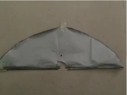
Fig2. Membrane Wing made of Mylar material
This models boasts about a real time camera which weighs only 3.9 grams and has best quality video recording for its real time surveillance and there has been a housing provided in the front for the camera in view of its safety during any crashes and to provide imaging with respect to pilot’s point of view to ensure the position of the vehicle using the reproduced images.
Fig3. Micro camera with inbuilt potentiometer
The inverted T-Tail configuration is being used after the model was tested with different types of wings like the T tail and other tail configurations as this configuration stands out for its better handling and hovering capabilities compared to the other configurations.
III. WORKING PRINCIPLE
The vehicle uses clap & fling mechanism for its synchronous flapping with a flapping rate controlled in between 10-20 Hertz, which is powered by coreless brushed motor producing
is housed in the projections of the gear box meshing with the teeth of the gear for its revolutions. The motor is connected to a integrated model which comprises of actuators and a speed controller which varies accordingly. It is placed below the Horizontal tail plane which serves our purpose during balancing. The vehicle is powered with a 70mAh LiPo battery which gives an endurance of about 4-5 minutes with normal manoeuvres. The camera is powered with a dedicated LiPo battery of the same configuration and a wireless receiver transfer the images produced to the display unit. It consists of a potentiometer which can tuned for a better range. The vehicle with all the components weighed 26.5 grams which gave a easy scope for balancing of the model successfully such that it produces required thrust for the particular configuration of the motor.
Fig 4. Actual model with T-Tail configuration
IV.RESULTS & OBSERVATIONS
main concern. The following sections will illuminate some of the specifics of the above generally stated conclusions. For this project, two wings, the separated biological wing and the biologically inspired engineered wing, were applied at 10-15 Hz in both air and vacuum to determine their dynamic characteristics when faced with said conditions, An efficient manufacturing technique of wings has been done using mylar material. The main features that were chosen to be emulated were the wing geometry, weight, and tail conditions as the model fancies an inverted T-Tail configuration for added control and manoeuvrability as these were considered very pertinent in the realm of proper emulation
and construction considerations. The
manufacturing technique was done in a iterative process by testing with various configurations, 3-D printing was chosen as the revolutionary materialization method due to its ability to manufacture near-exact geometries in all three dimensions which will allow for considerations to be made of both vein geometries and thicknesses. This method failed due to high inertial loading and material densities, producing wings that were not applicable for MAV usage. Smoke flow visualisation has been carried out to indicate the flow over the flapping model where flow was fixed in the test section using a custom made connector on which the model was seated. The result was a flow breakage near the wing tip which affected a smooth flow over it which was solved by placing weights at the leading edge tips which made the model more stable for a better flight.
Fig.5 Smoke flow visualization during flapping
Fig.6 Smoke flow visualization during idle condition
The next few iterations explored differing materials that exhibited various properties, however the filleted vein geometry was abandoned due to a distinct lack of
`manufacturability.' The next iterations
considered were two dimensions for
manufacturability and was tested with different wing materials like plastic and mylar before selecting mylar for its lower weight and resistance properties compared to plastic and that resulting in flight of the model successfully
ACKNOWLEDGEMENT
We thank Dr S K Maharana, Head of the Department and all other faculties of Aeronautical Department at Acharya Institute of Technology, Bangalore who have been a constant source of inspiration and helped us in every aspect, guiding and motivating us towards our goal.
REFERENCES
[1] Improving flight performance of the flapping wing MAV DelFly II Mark Groen*,Bart Bruggeman*, Bart Remes*, Rick Ruijsink*, Bas van Oudheusden*, Hester Bijl*Faculty of Aerospace Engineering, Delft University of Technology, Kluyverweg 1, 2629 HT Delft, The Netherlands
Vytla3 and P. G. Huang4 Wright State University, Dayton, Ohio, 45435-00001
[3] Design, Fabrication, and Testing of an Insect-Sized MAV Wing Flapping Mechanism, Michael L. Anderson1, Nathanael J. Sladek2, and Richard G. Cobb3 Air Force Institute of Technology, WPAFB, OH, 45433