Sharif University of Technology
Scientia IranicaTransactions D: Computer Science & Engineering and Electrical Engineering www.scientiairanica.com
Optimum pole arc oset in permanent magnet
synchronous generators for obtaining lowest voltage
harmonics
A. Dalcali
aand M. Akbaba
ba. Department of Electrical-Electronics Engineering, Karabuk University, 78050, Karabuk, Turkey. b. Department of Computer Engineering, Karabuk University, 78050, Karabuk, Turkey.
Received 22 December 2015; received in revised form 13 June 2016; accepted 19 July 2016
KEYWORDS Synchronous generator; Pole arc oset; Surface mounted; Voltage wave-shape; THD.
Abstract. In this study, the eect of parametric variation of pole arc oset distance on the performance of a Permanent-Magnet Synchronous Generator (PMSG) used in wind energy applications has been investigated. Fourier analyses of the voltage wave-shapes that are obtained by the parametric variation of the pole arc oset value have been made. The THD is determined for each voltage wave-shape. As a result of optimization study, the eciency and output power have been kept approximately constant. The THD of the output voltage has decreased.
© 2017 Sharif University of Technology. All rights reserved.
1. Introduction
Signicant advancement in environmental awareness and rapid decrease in fossil-fuel sources have resulted in the increased use of cheap and environmentally-friendly renewable energy sources [1-3]. Among the renewable energy sources, wind energy takes a vital role in decreasing foreign dependence on energy, improving energy reliability, and solving some of the environmen-tal problems. As such, the use of this component of renewable energy is rapidly increasing as the years pass by [4-9]. Dierent types of electrical generators used with wind turbines have some advantages and disad-vantages over one another. Among them, the use of PMSG is rising rapidly in parallel to the developments in Permanent Magnet (PM) technology [3,10-14].
*. Corresponding author. Tel.: +90 370 4332021; Fax: +90 370 4333290
E-mail addresses: [email protected] (A. Dalcali) doi: 10.24200/sci.2017.4357
In synchronous generators, mainly due to the magnetic saturation and spatial conguration of the pole face, the resultant air-gap ux density is not sinusoidal. As a result, the induced voltage is also not sinusoidal [15]. This issue has many disadvan-tages such as deteriorating the generator performance, causing some undesired eects on customer equipment, and high circulating currents between generators and innite bus [16,17].
Wang et al. [18], using FEM and analytic tech-niques, investigated the eect of pole arc to pole pitch ratio on the third harmonic of the back emf of the PM brushless DC motors. It has been proposed that at low-value pole arc to pole pitch ratio, the third harmonic of the back emf remains at the negligible level. However, this adversely aects the voltage THD, which means an increase in the harmonics of other orders, and motor performance. In [19], the eect of magnet shape and dimensions of disc type axial ux machines on the voltage distortion has been investigated. It is proposed that the voltage THD be minimum in the case of circular type magnets. It is also claimed that the
voltage THD is decreasing as the magnet thickness increases. In [20], it is shown that the no-load voltage THD of PM generators used with wind turbines is varying with the slot width and magnet pitch. Kim et al. [21] attempted to optimize the THD of PM generators by parametric variation of the number of poles, slot opening, ratio of pole angle, and pole size. It is pointed out that the pole angle and slot opening can be adjusted in such a way as to avoid 3rd voltage harmonic.
In this study, using FE analysis, design of a 2.5 kW surface-mounted PMSG suitable for use with wind turbines has been realized. Having completed the design phase, using parametric study approach, the pole arc-oset is varied between 0 to 45 mm. The shapes of the phase voltage and air-gap ux density distribution corresponding to each value of the pole arc oset value have been obtained. At the rated load, the Fourier coecients of the voltage wave-shapes have been determined. These are used to obtain THD% of the output voltage. In order to keep the output power approximately constant while varying the pole arc oset, the pole-embrace value has been also changed accordingly. In this investigation, electrical energy generation from small-scale wind turbines is targeted. Therefore, it is necessary to select a low-power and low-speed generators with large number of poles. Accordingly, a surface-mounted inner runner-type PMSG generator has been selected which features 1 poled, 2.5 kW, 120 V, 84 slots.
2. Design of PM synchronous generator
Design of PMSG starts with the following output Eq. (1):
S = 11:Kw1B:ac:
D 1000
2 : L
1000:n; (1) where S is the generator's apparent power in VA, B is specic magnetic loading in T (Wb/m2), D is the stator
outer diameter in mm, L is the stack length in mm, Kw1
is the stator winding factor, n is the rotor speed in rpm, ac is the specic electric loading in ampere-turns per meter (At/m); ac parameter mainly depends on
the rated power, frequency, and voltage as expressed in Eq. (2):
ac = (aDz) Z: (2) Phase voltages of a PMSG are expressed as given in Eq. (3) [15,22-24]:
2 4 vvab
vc
3 5 =
2
4 R0a R0b 00 0 0 Rc
3 5
2 4 iiab
ic
3 5
+ 2
4 LLaaab LLabbb LLcabc Lca Lbc Lcc
3 5 d
dt 2 4 iiab
ic
3 5 +
2 4 eeab
ec
3 5 :
(3) In terms of magnetic ux-linkages a; b, and c,
the voltage equation given in Eq. (3) can be re-written in the form of Eq. (4) as follows:
2 4vvab
vc
3 5
2
4R0a R0b 00 0 0 Rc
3 5 2 4iiab
ic
3 5 + ddt
2 4 ab
c
3
5 : (4) The remaining mathematical model of the PMSG, not present in this paper, can be found in detail in [24,25]. The generator design parameters are sum-marized in Table 1.
Figure 1 shows a 3D image of the initial design of a surface-mounted and inner runner conguration
Figure 1. 3D model of PMSG: (a) Complete view of the PMSG and (b) part section.
Table 1. Main data of the generator under study.
Parameters Values Parameters Values
Rated power (kW) 2.5 Stator outer diameter (mm) 280
Rated speed (rpm) 428.5 Air gap (mm) 0.8
Rated voltage (V) 120 Length of stator (mm) 54
Permanent magnet N35 Pole number 14
PMSG. Figure 1(b) shows the 1/14 part section of the full model used in FEM, which is obtained with the aid of master-slave boundary conditions.
3. Eects of pole arc oset value on the generator design
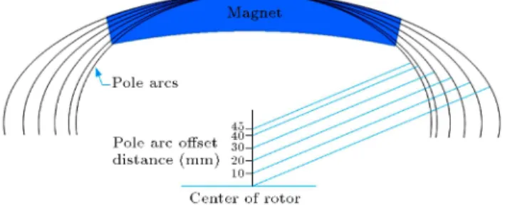
The pole arc oset can be determined as the distance of the center of the pole arc to the center of the rotor. The pole embrace is dened as the ratio of 1 over
2. 2 is the mechanical angle corresponding to one
pole pitch and 1 is the angle of one real pole covering
one-pole magnet [26,27]. According to the numerically calculated machine design procedure, initial pole arc oset value is dened. Then, the solution range and step size of the pole arc oset are dened. The oset point of the synchronous generator pole arc is initially selected as 0 mm and it is varied up to a maximum value of 45 mm. Figure 2 shows the change in the size of the PM oset points variation. As the oset point value increases, the eccentricity of the tips of PM increases. This leads to a drop in the volume of the PM. As shown in Figure 2, the maximum value of pole arc centre is \45 mm". This is the limit value and no more oset can be assigned to the dened pole number and outer diameter. At each value of the pole arc, the cogging torque, output power, eciency, induced torque, and load line voltage are investigated.
In order to obtain the generator's rated output power and rated voltage, the total ampere-turn value of the eld winding is required. It is determined by the combined contributions of ampere-turn of the stator body, stator teeth air gap, pole face, pole body, and rotor center. All of these parts of the generator from the magnetic circuit reluctance, except for the air-gap reluctance, are all non-linear circuit elements [15,16]. At nominal load, the air-gap ux density waveforms of the generator are given in Figure 3 against the varying pole arc oset values.
More sinusoidal air-gap ux density distributions can be obtained by changing the pole arc oset. The nearest sine waveform was achieved when the oset value was set to 45 mm in the analysis. The resulting waveforms can be expressed as Fourier series given in
Figure 2. Variation of the parameters of pole arc oset.
Eq. (5) [28]:
Bg() = A0+ 1
X
n=1
(Ancos n + Bnsin n); (5)
where Bgis the radial air-gap ux density, is the space
angle in electrical degrees, n is the harmonic number, and An and Bn are Fourier coecients.
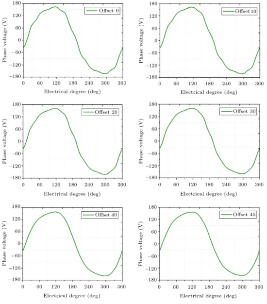
The waveform of the voltage induced in the gener-ator windings is a function of the magnetic ux density waveform at the air gap [29]. Therefore, a distorted ux density distribution will lead to a distorted terminal voltage waveform. The simulated induced voltage waveforms at the rated load corresponding to the varying values of the pole arc oset are illustrated in Figure 4. Similar to the air-gap ux density waveform, the best voltage waveform close to a sine wave, is obtained for an oset value of 45 mm.
The magnetic ux density distribution corre-sponding to 40 mm pole arc oset value is given in Figure 5. It is obtained by using master-slave boundary conditions. Careful observation of this gure reveals that the ux density distribution is convenient as far as the saturation of the used steel-sheets is concerned. The variation of the eciency and power of the generator, which is designed for varying pole arc oset values, is shown in Figure 6. It is already mentioned above that it is desired to keep the output power almost constant. To achieve this while varying the pole arc oset value, the pole-embrace value is also varied accordingly. In this process, it is observed that the eciency of the generator also remains almost constant.
4. Total harmonic distortions value of the induced voltage
In power systems, uninterruptable and high-quality power is always highly demanded. Therefore, for reliable operation of the power systems, it is important to perform the Fourier analysis of the voltage waveform and investigate the harmonics content. The most common way of performing this analysis is to sample the voltage waveform, and then nd the average value of each sample [30]. Then, the Fourier coecients are obtained as given in Eqs. (6) and (7).
An= m2 m
X
k=1
(yk sin(n k)); (6)
and Bn =m2
m
X
k=1
(yk cos(n k)): (7)
In the above equations, m is the number of samples in one period of the voltage waveform, k,
Figure 3. Air-gap ux density spatial distribution.
is the center-point angle of each sample, (k = 1; 2; : : : ; m), yk is the average value of each voltage
waveform sample corresponding to k, and n is the
harmonic order. Having obtained the Fourier coe-cients, the voltage waveform can be expressed as given in Eq. (8) [30]:
V () =qA2
1+ B12: sin
h
+ tan 1B1
A1
i + +pA2
n+ Bn2: sin
+ tan 1
Bn
An
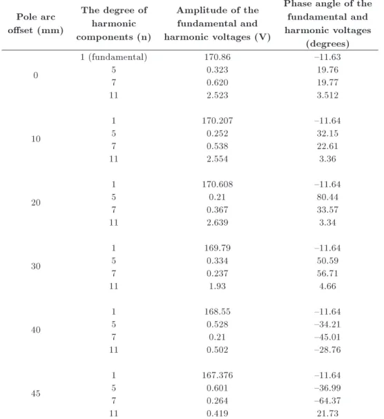
: (8) The variations of the amplitude and phase angle of the harmonics corresponding to the various pole arc oset values are given in Table 2.
Knowing that the total voltage is composed of fundamental component and the harmonics, then it can
be re-written in the form of Eq. (9) [31]:
Vs(t) = Vs1(t) +
X
h=1Vsh(t): (9)
Here, Vs(t) is the phase voltage, Vs1(t) is the
fundamental component, and Vsh(t) is the harmonic
voltage component at fhharmonic frequency. The total
distortion in voltage waveform Vdis(t) can be expressed
as given in Eq. (10) and it is measured via the concept of percent total harmonic distortion factor (THD%), which is expressed as in Eq. (11):
Vdis(t) = Vs(t) Vs1(t)
X
h=1Vsh(t); (10)
%THD = 100 VVdis
s1: (11)
Figure 4. Phase voltage waveforms.
Figure 5. Magnetic ux density distribution (2D and 3D).
waveforms given in Figure 3 against the variation of the pole arc oset and embrace values, obtained through Maxwell analysis at the rated load, is given in Table 3. As a result of the Fourier analysis, it is observed that
Figure 6. Eciency and power versus oset changes.
a pole arc oset value of 40 mm appears to be the optimum value. For this value of the pole arc oset, the following performance values are obtained: generator output power of 2454 W, eciency of 88.24%, and THD% of 0.52.
Table 2. Variation of the gain and phase angles of the voltage harmonics against the pole arc oset values. Pole arc
oset (mm)
The degree of harmonic components (n)
Amplitude of the fundamental and harmonic voltages (V)
Phase angle of the fundamental and harmonic voltages
(degrees)
0
1 (fundamental) 170.86 {11.63
5 0.323 19.76
7 0.620 19.77
11 2.523 3.512
10
1 170.207 {11.64
5 0.252 32.15
7 0.538 22.61
11 2.554 3.36
20
1 170.608 {11.64
5 0.21 80.44
7 0.367 33.57
11 2.639 3.34
30
1 169.79 {11.64
5 0.334 50.59
7 0.237 56.71
11 1.93 4.66
40
1 168.55 {11.64
5 0.528 {34.21
7 0.21 {45.01
11 0.502 {28.76
45
1 167.376 {11.64
5 0.601 {36.99
7 0.264 {64.37
11 0.419 21.73
Table 3. Variation of % voltage THD with the variation of the pole arc and embrace.
Oset (mm) Embrace THD (%)
0 0.77 1.538
10 0.78 1.56
20 0.81 1.713
30 0.84 1.34
40 0.9 0.52
45 0.99 0.48
5. Conclusion
In this paper, the optimal pole arc oset for PMSG that is expected to have low THD and high eciency has been investigated. For the optimal design, pole arc oset value was dened as a variable parameter. While obtaining new designs by varying the pole arc-oset value, utmost care has been exercised to maintain
the generator output power almost constant. For this reason, as the value of the pole arc oset is varied, the embrace value is also varied in order to obtain almost constant output power value. Spatial distribution of the air-gap ux density and shape of the phase voltage, corresponding to the various pole arc oset values, have been obtained. Their Fourier analyses have been made. It is well known that as the spatial distribution of the air-gap ux density approaches to a sine wave, the harmonics of the voltage waveforms reduces. As a result, the overall performance of the generators improves. Reduced generator voltage harmonics also results in the reduced circulation currents between the generator and voltage network. As a result of the performed analyses, a pole arc oset value of 40 mm and a pole embrace value of 0.9 have been identied as highly convenient values. For these values, generator eciency of 88.24% and THD value of 0.52% have been obtained.
References
1. Sefa, I. and Altin, N. \Grid interactive photovoltaic inverters-A review" [Gunes Pili Ile Beslenen sebeke Etkilesimli Eviriciler - Genel Bir Bakis], J. Fac. Eng. Arch. Gazi Univ., 24(3), pp. 409-424 (2009).
2. Dalcali, A., Celik, E. and Arslan, S. \Design of a microprocessor based electronic governor system for micro and mini hydroelectric power plant" [Mikro ve mini hidroelektrik santralleri icin mikrodenetleyici tabanli bir elektronik governor sisteminin tasarimi]", Erciyes University, Journal of the Institute of Science and Technology, 28(2), pp. 130-135 (2012).
3. Ozturk, N., Dalcali, A., celik, E. and Sakar, S. \Op- timum design of permanent magnet wind generator based on low cogging torque criteria", III. European Conference on Renewable Energy Systems, Antalya (2015).
4. Patil, K. and Mehta, B. \Modeling and simulation of variable speed wind turbine with direct drive per-manent magnet synchronous generator", International Conference on Green Computing Communication and Electrical Engineering, Coimbatore, pp. 1-6 (2014). 5. Huang, C., Li, F. and Jin, Z. \Maximum power
point tracking strategy for large-scale wind generation systems considering wind turbine dynamics", IEEE Transactions on Industrial Electronics, 62(4), pp. 2530-2539 (2015).
6. Pillai, S.K. and Samuel, P. \Dynamic behaviour of UPF rectier for PMSG based wind energy conver-sion system", International conference on embedded systems, Coimbatore, pp. 200-205 (2014).
7. Wang, Y., Meng, J., Zhang, X. and Xu, L. \Con-trol of PMSG-based wind turbines for system iner-tial response and power oscillation damping", IEEE Transactions on Sustainable Energy, 6(2), pp. 565-574 (2015).
8. Liu, T., Huang S., Deng, Q., Pu, Q. and Huang, K. \Eect of the number of slots per pole on performance of permanent magnet generator direct-driven by wind turbine", International Conference on Electrical Ma-chines and Systems, Beijing, pp. 1-4 (2011).
9. Van, T.L., Nguyen, T.H and Lee, D. \Advanced pitch angle control based on fuzzy logic for variable-speed wind turbine systems", IEEE Transaction on Energy Conversion, 30(2), pp. 578-587, (2015).
10. Polinder, H., van der PijI, F.F.A., de Vilder, G.-J. and Tavner, P. \Comparison of direct-drive and geared generator concepts for wind turbines", International Conference on Electric Machines and Drives, San Antonio, pp. 543-550 (2005).
11. Dursun, E. and Binark, A.K. \Generator which are used in wind turbine (Ruzgar Turbinlerinde Kullanilan Generatoler)", VII. National Clean Energy Sympo-sium, Istanbul, pp. 667- 674 (2008).
12. Kurt, E. and Gor, H. \Electromagnetic design of a new axial ux generator", 6th International Conference
on Electronics, Computers and Articial Intelligence, Romania, pp. 39-42 (2014).
13. Baybpriya, B. and Anita, R. \Modelling, simulation and analysis of doubly fed induction generator for wind turbines", Journal of Electrical Engineering, 60(2), pp. 79-85 (2009).
14. Sekerak, P., Hrabovcova, V., Pyronen, J., Kalamen, L., Rafajdus, P. and Onufer, M. \Ferrites and dier-ent winding types in permandier-ent magnet synchronous motor", Journal of Electrical Engineering, 63(3), pp. 162-170 (2012).
15. Gurdal, O. Designing of Electrical Machines [Elektrik makinlarinin Tasarimi], Bursa Orhangazi University Press, Bursa, Turkey (2015).
16. Tarimer, I., Sakar, S. and Dalcali, A. \Eects of structural design of pole Arc oset in a salient pole generator to obtaining sinusoidal voltages with the least harmonics", Przeglad Elektrotechniczny, 86(11a), pp. 357-362 (2010).
17. Feshki Farahani, H., Khalili, M., Rabiee, A. and Ghaz-izadeh, M.S. \On the application of plug-in hybrid electric vehicle to compensate network harmonics: A multiobjective approach", Scientia Iranica D, 21(6), pp. 2177-2185 (2014).
18. Wang, K., Shen, J.X., Zhou, F.Z., Qiu, R.H. and Lin, R.G. \Optimal design of magnet pole arc con-sidering utility of third-harmonic back-EMF in high-speed sensorless brushless DC motors", Proceeding of International Conference on Electrical Machines and Systems, Seoul, pp. 680-684 (2007).
19. Boccaletti, C., Felice, P.D., Petrucci, L. and Santini, E. \Parametric analysis of axial ux wind genera-tors focused on total harmonic distortion evaluation", IET Renewable Power Generation, 5(2), pp. 148-159 (2011).
20. Potgieter, J.H.J. and Kamper, M.J. \Torque and voltage quality in design optimization of low-cost non-overlap single layer winding permanent magnet wind generator", IEEE transactions on Industrial Electron-ics, 59(5), pp. 2147-2156 (2012).
21. Kim, Y.H., Kwon, S.O., Tao, S. and Hong, J.P. \Initial design using space harmonic analysis methods in permanent magnet synchronous machines", 14th Biennial IEEE Conference on Electromagnetic Field Computation, Chicago, p. 1 (2010).
22. Wang, D., Wang, X., Yang, Y. and Zhang, R. \Opti-mization of magnetic pole shifting to reduce cogging torque in solid-rotor permanent-magnet synchronous motors", IEEE Transactions on Magnetics, 46(5), pp. 1228-1234 (2010).
23. Chen, N., Ho, S.L. and Fu, W.N. \Optimization of permanent magnet surface shapes of electric mo-tors for minimization of cogging torque using FEM", IEEE Transactions on Magnetics, 46(6), pp. 2478-2481 (2010).
24. Duan, Y. Method for Design and Optimization of Surface Mount Permanent Magnet Machines and In-duction Machines, Georgia Institute of Technology (2010).
25. celik, E. \Graphical interface aided simulation of speed control of permanent magnet synchronous motor with genetic based fuzzy logic controller" [Surekli miknatisli senkron motor hiz denetiminin genetik tabani bulanik mantik denetleyici ile arayuz destekli simulasyonu], Gazi University Institute of Science (2012).
26. Bayindir, R., Topaloglu, I. and Ocak, C. \Investigation of the eect of magnet thickness on motor losses of PM BLDC machines using parametric approach method", International Conference on Power Engineering, En-ergy and Electrical Drives, Malaga, pp. 1-4 (2011). 27. Zheng, P., Liu, Y., Wang, T. and Cheng, S. \Pole
optimization of brushless DC motor", IEEE Industry Applications Soc. 39th Annu. Meeting, pp. 1062-1067 (2004).
28. Basman, F. Harmonics in Power Systems and Filter [elektrik enerji sistemlerinde harmonik ve ltreleme], Sakarya University Institute of Science (2006). 29. Oner, Y., Senol, I., Bekiroglu, N. and Aycicek, E.
\Magnetic analysis of fractional slot permanent mag-net sychronous machine [Kesirli Oluklu Surekli Mik-natisli Senkron Makinanin Manyetik Analizi], Journal of Engineering and Natural Sciences, Sigma 30(4), pp. 436-446 (2012).
30. Kocatepe, C., Uzunoglu, M., Yumurtac, R., Karakas, A. and Arikan, O. Harmonics in Electrical Installa-tions [elektrik tesislerinde harmonikler], Birsen Press, Turkey (2003).
31. Mohan, N., Undeland, T.M. and Robbins, V.P. Power Electronics, John Wiley & Sons, USA (2003).
Biographies
Adem Dalcali was born in Turkey in 1986. He received his MSc degree from the Institute of Science and Technology of Gazi University in 2013. He is currently a Research Assistant in Electrical and Elec-tronics Engineering at Karabuk University and also is working towards the PhD degree at the same university. His research interests include CAD of electric machines, numerical analysis of the electromagnetic eld in elec-trical machinery.
Mehmet Akbaba received MSc degree in Electri-cal Engineering from Istanbul TechniElectri-cal University in 1971, and PhD degree in the same eld from Strath-clyde University, UK, in 1977. From 1978 to 1983, he was with the Electrical and Electronics Engineering Department, Karadeniz Technical University, Turkey, as a Graduate Assistant, Assistant professor (1978) and Associate Professor (1983),respectively. From 1983 to 2012, he was with the Electrical and Computer Engineering Departments, University of Bahrain as an Assistant Professor (1983), Associate Professor (1986) and full Professor (1995) respectively. Currently, he is with the Computer Engineering Department, Karabuk University, Turkey. He has published over 70 papers in refereed journals and international conferences. His current research interests include modeling and analy-sis of electromechanical and photovoltaic systems and power electronics.