Guide for Safety with
Published by the Occupational Safety and Health Service Department of Labour
Wellington New Zealand Issued October 2002 ISBN 0-477-03665-1
The following utility companies, organisations and associations assisted in the production of this guide:
Telecom New Zealand Ltd. DELTA
Transpower New Zealand Ltd.
New Zealand Contractors’ Federation Inc. PowerCo Ltd.
Natural Gas Corporation UnitedNetworks Ltd.
Electricity Engineers Association of New Zealand Inc. Orion New Zealand Ltd.
Networks South Ltd. TelstraClear Ltd.
Gas Association of New Zealand Inc. Electricity Ashburton
Auckland Utility Operators’ Group Inc. New Zealand Water and Waste Association Inc.
FOREWORD
It is with pleasure that I write this foreword to the Guide for
Safety with Underground Services. I am especially pleased that
during the process of development, those industries involved with underground services have been consulted and have been able to contribute to the recommended safety procedures. This document replaces an earlier version, and sets out agreed work methods and preferred work practices for the location and excavation of underground services. As such, the
document should assist those who have responsibilities under the Health and Safety in Employment Act 1992.
The Electricity Engineers’ Association (EEA) is to be
congratulated for facilitating the development of this guide and I acknowledge the support of the various utility companies and utility associations in the printing of this document. I am confident that those who use it will find it very useful in assisting them to manage hazards in the underground services work environment.
By using the information contained in this guide, industry members can be confident that they will be managing their hazards in an acceptable manner. This can only lead to enhanced health and safety in the workplace.
R J M Hill General Manager
CONTENTS
Foreword 3
Introduction 7
Application 8
Who Should Use This Guide 9
How To Use This Guide 1 0
Definitions 1 1
The Dangers 1 2
11.1 Electricity Cables 12
11.2 Gas Pipes 12
11.3 Liquid Petroleum Services or Oil Pipelines 13
11.4 Water and Waste Water Pipes 13
11.5 Telecommunication Cables 13
11.6 Costs and Damages 13
Safe Systems of Work 1 5
12.1 Plans and Mark-Outs 15
12.2 Cable and Pipe Locating Devices 16
12.3 Safe Digging Practice 16
Plans and Mark-Outs 1 9
Cable and Pipe Location Devices 23
Safe Digging Practice 27
Safe Systems for Work for Trenchless Methods 32
New Housing Developments 33
Installation of New Services Near Existing Services 34
Demolition Sites 35
Appendices
Appendix 1: Electricity Cables 37
Appendix 2: Gas Pipes 44
Appendix 3: Water and Waste Water Pipes 51
Appendix 5: Legislation and Guides Relating to
Underground Services 54
Appendix 6: First Aid 69
Appendix 7: Work Procedures 71
Appendix 8: Duct Colours Used in the Past 74
Appendix 9: Contact Telephone Numbers 76
References 78
Figures
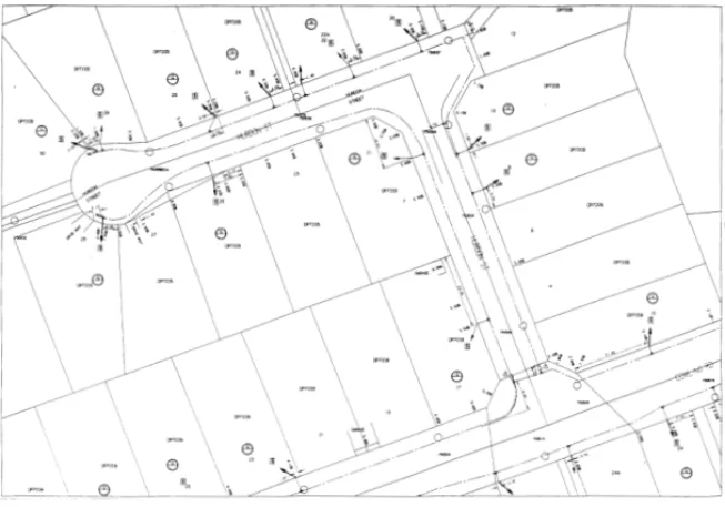
Figure 1: Gas plan 23
INTRODUCTION
1 Many incidents, some of which can involve serious personal injury, occur when underground services are damaged during excavation and other work involving ground penetration. Not all damage is immediately obvious; some only becomes apparent years after work has been carried out, for example, when an underground service is damaged and it corrodes over a long period of time. In addition to the risk of personal injury, damage can be very costly and can have considerable ongoing effects. Consider, for example, the effect on a hospital or a home kidney-dialysis patient if services are lost.
2 This guide outlines the hazards that can arise from work near underground services and gives advice on how to reduce the risk. It deals principally with risks to health and safety and is not so concerned with damage that has no personal risk. However, the precautions needed to reduce the risk of personal injury will reduce the risk of damage generally, and lower the cost of performing work to utilities, contractors, and society.
3 It is stressed that many of the underground services encountered in road reserves present a very serious and
potentially fatal hazard if damaged (for example: electricity and gas). As a consequence, personnel engaged in excavation work have a particular responsibility under the Health and Safety in Employment (HSE) Act 1992 to identify and manage these hazards.
APPLICATION
4 The guide applies to all situations where underground services may be found and where work is undertaken which involves penetrating the ground at or below surface level.
Persons excavating in public areas also need to refer to: (a) Associated requirements for the temporary control of
traffic (refer Code of Practice for Temporary Traffic
Management issued by Transit New Zealand).
WHO SHOULD USE THIS GUIDE
5 This guide should be used by all those who haveresponsibilities under relevant legislation (see Appendix 5), including employers, employees, owners of underground services and those concerned with planning, arranging, and supervising work near such services. This includes work carried out by or on behalf of the utilities, and also roadworks, construction and demolition work. The guide is aimed
primarily at central and site management (including travelling supervisors and leaders of groups of personnel on site) but it also contains a suggested text for information that could be used by personnel directly engaged in excavation work on site (see Appendix 7).
HOW TO USE THIS GUIDE
6 This guide is divided into a main text and nine appendices. Many of the precautions to prevent damage apply equally to all types of buried service, and the main text sets out a general system of work. More specific precautions on each of the four types of buried underground services are given in Appendices 1 to 4, which need to be read in conjunction with the main text. The other appendices deal with relevant legislation, first aid, a suggested text for employee information, historic duct colours and useful contact telephone numbers.
7 The original guide was considered by a joint working party with representation from OSH and industry groups which drew on a wide range of expertise. The working party
concluded that, in many cases, there are no suitable alternatives to the precautions advocated in this guide. This view was confirmed in 1998/9 with the first review of this guide. Personnel involved in this type of work who wish to carry it out in some other way than that advocated should ensure they achieve an equal or greater standard of safety.
DEFINITIONS
8 The term ‘service(s)’ means all underground electricity, gas, water, steam, waste water (sewer, storm water),
telecommunications plant, and liquid petroleum services and oil pipelines. It does not include underground structures such as brick sewers, railway tunnels, etc.
9 The term ‘service connection’ means a pipe and/or cable linking the main underground service with individual premises.
1 0 The term ‘utility’ is used to describe the owner of a service, and may include an electricity, gas, or telecommunications company, or a territorial authority in its capacity as a service owner.
THE DANGERS
1 1 The main dangers which may arise from work near underground services are summarised below:
11.1 Electricity Cables
Injuries resulting from damage to live electricity cables are usually caused by the explosive effects of arcing current, and by any associated fire or flames which may follow, when the sheath of a cable and the conductor insulation is penetrated by a sharp object such as the point of a tool. Such damage can also occur when a cable is crushed or bent severely enough to cause internal contact between the conductors or between the sheathing and one or more of the conductors. This typically causes severe and potentially fatal burns to the hands, face and body. Direct electric shock is rare but not impossible. (See also Appendix 6.)
11.2 Gas Pipes
Damage to gas pipes can cause escapes which may lead to fires or explosions if an ignition source is present.
There are two types:
(a) Damage which causes an immediate escape; and, (b) Damage that causes an escape some time later. The
damage may occur at the time the work is carried out (for example damage to a pipe wrapping may eventually lead to corrosion). Alternatively, poor reinstatement may leave a pipe inadequately supported or subjected to unequal forces, or at risk of damage through penetration by sharp objects in the back-fill.
In the former case, the risk is to both the people carrying out the work and to others in the vicinity; in the latter case the risk is mainly to members of the public.
11.3 Liquid Petroleum Services or Oil
Pipelines
Damage to these services is similar to that for gas pipelines. In addition, there are significant environmental risks, particularly near waterways.
11.4 Water and Waste Water Pipes
Damage to water and waste water pipes is less likely to cause injury, but a jet of water from a high-pressure water main can injure personnel or damage adjacent services. A leak from an underground pipe can wash away subsoil and reduce the support for adjacent services, highways and structures. Similarly, leaks can wash away support for thrust blocks making them unstable.
Further dangers include the risks of flooding the trench or low-lying areas such as nearby basements. While most sewers rely upon gravity, some sewage is pumped at pressure. The main danger from damage to a sewer is the possibility of contamination and the risk to health.
11.5 Telecommunication Cables
With the exception of fibre optic cabling (refer Appendix 4), there is little ‘direct’ risk of personal injury from damaging a telecommunications cable. There is, however, the potential for ‘indirect’ danger if emergency services cannot be contacted. All business is now absolutely reliant on electronic
communication and a damaged circuit can cause extensive disruption to services. Loss of data results in loss of revenue and repairs to optical fibre and multi-pair cables can be extremely costly.
11.6 Costs and Damages
All utility owners may take legal action to recover both repair costs and costs of lost business from the party responsible for
damage. Further individual businesses who suffer loss through the interruption to a service may seek to recover such losses from the responsible party.
SAFE SYSTEMS OF WORK
1 2 Buried services are widespread and it should be assumed that they are present until it is proved otherwise. This part of the guide aims to help minimise the possibility of damaging them. It sets out a safe system of work which is based on obtaining, before work begins, as much information as possible about buried services in the area and then using that information to ensure safe digging.
The safe system of work has three basic elements:
12.1 Plans and Mark-Outs
Plans or other suitable information about all buried services in the area should be obtained from each service owner before excavation work starts. The service owner should do everything that is reasonably practicable to ensure that such information is made available to parties making inquiries. Many service owners will, on request, offer a service to trace and mark-out their services on the ground, and you should avail yourself of this service and be familiar with the telephone numbers to call. (Refer Appendix 9.)
Ensure that the plans being used are the most recent issue from the service owners and have not been reproduced by a third party. Never rely on information from someone’s memory and treat plans as indicative only.
When it is not possible to obtain plans, as may be the case when emergency or other unforeseen work* has to be
* Unforeseen work is work that occurs at such short notice that it cannot be planned in
advance. The term does not cover emergencies in which people are at risk, but does include situations where it is considered necessary to start or continue work despite problems that would normally require further information from service owners, etc. However, there may be many situations where it would be prudent to delay
unforeseen work in order to obtain more information. In particular, a client may plan a job well in advance but only pass it to the contractor at the last minute. Clients should either pass on buried service information to the contractor in good time or
undertaken, the excavation should be carried out with the assumption that there are buried services in the vicinity, and carried out accordingly.
Account should be taken of any indications that buried services exist, such as the presence of street lights, illuminated traffic signs, valve pit covers, telecommunications chambers and service pillars, obvious signs of previous trench
reinstatement, etc. However, the absence of such indications does not necessarily mean that there are no buried services. (For further information on plans and mark-outs, see also paragraphs 17 to 24.)
12.2 Cable and Pipe Locating Devices
In addition to any mark-out service that has been provided, suitable cable and pipe locating devices should be used on site, in conjunction with any available plans, to determine as accurately as possible the position of traceable underground services in or near the proposed work area. These devices are relatively inexpensive and should be available at all work sites. Compared to the cost of the repair of a damaged service, they are a good investment and will recover their cost very quickly. Locators will only detect metallic objects and will not detect plastic objects unless a tracer wire is incorporated with the pipe, or a tracing transmitter is able to be propelled through the pipe. (For further information on cable and pipe locating devices, see also paragraphs 25 to 28.)Note: Locating devices must not be relied upon as the only check used.
12.3 Safe Digging Practice
Excavation work should be carried out carefully, and follow recognised safe digging practice. (For further information on safe digging practice, see also paragraphs 29 to 38.)
1 3 These key elements – plans and mark-outs, locators and safe digging – complement each other, and all three should be used when working near buried services. They are covered in more detail later in the guide.
1 4 Using only one is not enough: for example, a cable may be shown on a plan as a straight line, with measurements taken from fixed objects at the time of installation, whereas in practice the cable may twist and turn, or may have been moved out of position. Reliance on the plan alone would give a false position, but this could be alleviated by the correct use of a cable locator. If several cables are close together, a locator may show them as a single cable, whereas the plan would help give a more accurate picture.
1 5 Personnel responsible for excavation work where buried services may be present should liaise with the service owners (normally the utilities but sometimes other statutory bodies or private companies may be involved) when planning and carrying out the work. Service owners accept the need for close co-operation with those who have to excavate in the vicinity of their plant. In most instances they may be prepared to help locate and identify the plant when requested, usually by sending a representative to the site. Further ways of
improving and extending co-operation, particularly with other utilities, local authorities and contractors, who have to perform a considerable amount of excavation in road reserve and on other public land, are usually welcomed and should be proposed.
1 6 The procedures and arrangements necessary for avoiding danger should be written into, or form part of, employers’ statutory safety policies and emergency procedures.
Employees should receive adequate instruction and training in the above procedures (see Appendix 7) as a basis for training programmes.
It is particularly important that anyone who uses a locator should be competent in the use and limitations of that particular type or model.
PLANS AND MARK-OUTS
1 7 The owners of underground services must be contacted for information and plans well before excavation is due to start. Where consultants and clients (which in some circumstances will include utilities and local authorities) obtain the
information they must pass it on to the main contractor, who must in turn pass it on to those involved in excavation and groundwork. It may be possible to amend some projects at the planning stage to avoid existing buried services, or routes or areas of particular service congestion. For major projects, an early approach to services owners is essential as it may be possible to divert some services from the excavation area.
1 8 The great majority of buried underground services belong to one or other of the local or national utilities. Privately-owned services may be found on or near commercial, industrial, military or other sites, and where possible the owners should be consulted. Power and telecommunications cables in road reserve may not necessarily be owned by the local electricity utility, for example, traffic light controls, and connections between buildings on a university campus (see paragraph A1.1 of Appendix 1).
1 9 Owners of services should either provide plans, which show the recorded line and depth (where known) of all their known plant buried in the proposed work area, or other suitable information which assists in protecting the safety of persons. They are likely to receive many routine applications for information and should consider how best to make information available at short notice. Where reasonably practicable, arrangements should also be made to deal with requests for information for emergencies outside of office hours, so that working parties can be given plans of
underground services positions when they receive their work instructions.
Some owners may have reservations, for reasons of security, about supplying copies of their underground service plans for such areas as those around important civil and military establishments. In such cases, an alternative method should be used; for example, a representative could be sent to the site to give information to legitimate contractors/utilities, etc.
20 Plans are not normally drawn to scale but even if they claim to be, they should not be relied upon to obtain distances. The draughts-person may have made a mistake or reproduction may have changed the scale, especially if the plan was obtained from a microfiche slide or digital map or transmitted by facsimile.
However, plans can give a good indication of the location, configuration and number of underground services at a particular site, and will help subsequent tracing by locators. Those in charge of site work, and operators of locators, should be aware that plans may show spare ducts, and that the accuracy of plans is limited because:
(a) The position of reference points (e.g. the kerb line) may have changed since the plans were drawn;
(b) Regrading of any surface may mean that the depths shown are now incorrect;
(c) Services, particularly cables, may have been moved without the authority or knowledge of their owners; (d) In many cases service connections are not marked; (e) Services, marked as straight lines may, in practice, twist
and turn; and
(f) In order to avoid too tight a bending radius, cables may have been laid in horizontal loops outside substations, switch-rooms, and at the base of poles, etc.
Further notes on the use and limitations of plans for electricity cables and gas pipes are given in Appendices 1 and 2, and examples are shown in Figures 1 and 2. Particular care should
be taken where topographical changes have occurred since services were laid. Adequate instruction and training in how to read and interpret the plans must be given to personnel who need to use them.
In all cases, it is important for the original issues of service plans to be held on site.
2 1 Plans, once issued by a service owner, will only have a limited ‘life’ with respect to their accuracy as further works are performed. In some cases, this ‘life’ can be as little as 2 weeks, and it is essential that service owners be asked to revalidate plans if for some reason there is a delay before excavation work commences.
22 Most utility service owners will not only stamp a validity period on a plan upon issue, but will provide a set of standard conditions either with, or as a stamp, on the plan. These conditions need to be understood and complied with during the course of the excavation. Examples of conditions could include a maximum distance a service is allowed to be
unsupported, special back-filling requirements around services, minimum approach distances, etc.
23 Even when work has to start without plans, as may be the case for emergency and unforeseen work, every effort should be made to locate buried underground services, and service owners should be consulted.
In the meantime, it should be assumed that buried services are present and digging should proceed with extreme caution, and only after a locator has been used to detect metallic cables and pipes. It is particularly important that anyone carrying out excavations in such circumstances should be adequately trained and supervised.
(Where plans are not available in a situation, only excavation by hand should be carried out, until the location of any services has clearly been established.)
24 Most utilities will offer and provide a mark-out service on request. For work planning purposes, each utility service owner should be given at least 24 hours’ notice before work commences.
Having a site properly marked-out can be of great assistance to a contractor, but does not discharge that contractor from the responsibility of taking all necessary precautions as contained in this guide.
Figure 1: Gas plan
CABLE AND PIPE LOCATION
DEVICES
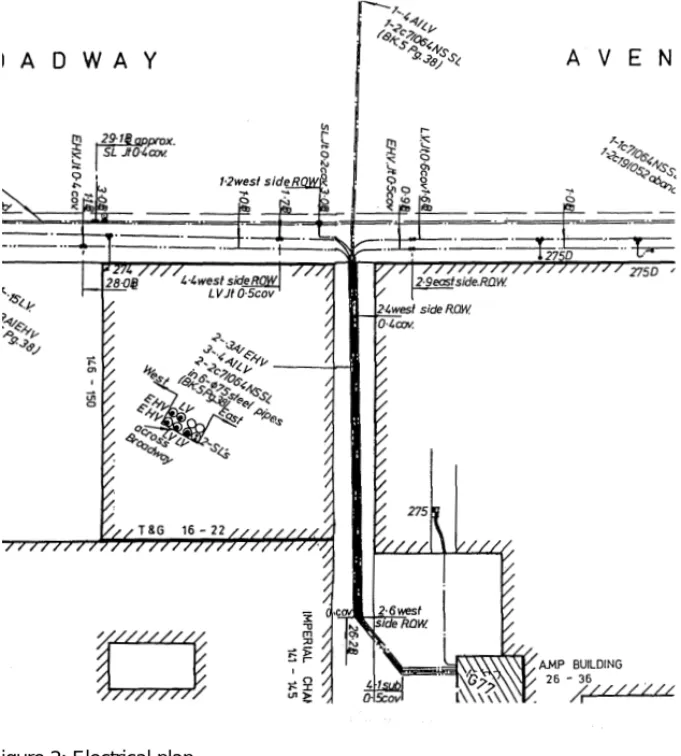
25 The position of any services in or near the proposed work area should be pinpointed as accurately as possible by means of a locating device, in conjunction with any available cable plans or other suitable information (see Figures 1 and 2). Plans will help the operator using the locator to interpret the signal, and so give the maximum information to those involved with the work before excavation starts. Do not rely solely on cable and pipe location devices for the detection and location of cables and pipes.
Figure 2: Electrical plan
26 Various locators are available, and guidance on their selection and use should be in accordance with the manufacturer’s instructions. The main types of locator available can be classed as follows:
(a) Hum detectors: These are receiving instruments which detect the magnetic field radiated by live electricity cables which have a current flowing through them. They will not detect, for example, service connection
cables to unoccupied premises or street lighting cables in the daytime, because little or no current is flowing. (b) Radio frequency detectors: These are receiving
instruments which respond to low- frequency radio signals, which may be picked up and re-emitted by cables and long metallic pipes. If radio frequency detection is used, other metallic objects may re-radiate the signal and results may vary appreciably according to locality, length of the buried cable or pipe and distance from the termination, and geographical orientation. (c) Transmitter-receiver instruments: A small portable
transmitter or signal generator can be connected to a cable or pipe, or placed very close to it so that the signal is induced into it. The receiver can then detect this signal. Usually the location of some part of the cable or pipe needs to be already known so that the transmitter can be properly positioned, and these locators generally require more skill to operate than other types. They can, however, provide useful information in difficult situations where the techniques in (a) and (b) have not been successful.
(d) Metal detectors: Conventional metal detectors will usually locate flat metal covers, joint boxes, etc., but may well miss round cables or pipes. They can be a useful tool for finding inspection points that may provide connection points for a transmitter.
Some commercially available instruments use more than one of these techniques and may include a depth
measuring facility.
27 The degree of confidence with which buried services can be detected depends on a number of factors such as the
characteristics of the device being used, the type and depth of the service, the magnitude of the current carried by the cable, and the effects of other cables and metal pipes close by. It can
also be affected by the training, skill, hearing and experience of the operator.
In particular, a locator may not be able to distinguish between cables or pipes running close together and may represent them as a single signal.
If two services are sited one above the other, it may not be possible to detect the lower one. Having dug and found one cable or pipe does not mean that there is not another close by. Frequent and repeated use should be made of locators during the course of the work. Locators will not detect plastic pipes or other non-metallic ducts and services unless either:
(a) A metallic tracer wire has been laid with the pipe. This enables a signal transmitter/receiver to be used. Plastic gas and water pipes and fibre-optic cables are the non-metallic services most likely to be encountered and few have been laid with metallic tracer wires in the past. (b) A small signal transmitter is inserted into and pushed
along the pipe (where practicable). This is a sophisticated technique which is not likely to be appropriate for most jobs.
28 Locating devices should always be used in accordance with the manufacturer’s instructions and should be regularly checked and maintained in good working order. The line of any identified services should be noted and marked with waterproof crayon, chalk or paint on paved surfaces (any residual markings being erased after excavation as much as possible) or with wooden pegs in grassed or un-surfaced areas. Steel pins, spikes or long pegs, which could damage services laid at shallow depth, should not be used.
Note: Locating devices must not be relied upon as the only check used.
SAFE DIGGING PRACTICE
29 In conjunction with location devices and plans, trial holes by careful hand excavation are essential before any
excavation is commenced. Hand digging must continue until all of the services have been found. If there is any doubt as to where the service is located, stop work and consult with the service owner.
Special care should be taken when digging above or close to the assumed line of such a service. Hand-held power tools and mechanical excavators are the main causes of danger and they should not be used too close to underground services. Advice on appropriate safety margins from electricity cables, gas pipes, and telecommunications cables, is given in Appendices 1, 2 and 4.
30 Incorrectly used hand tools are a common source of accidents but when carefully used, they can normally provide a
satisfactory way of exposing buried services, once the approximate positions have been determined using plans and locators. Every effort should be made to excavate alongside the service rather than directly above it. Final exposure of the service by horizontal digging is recommended as the force applied to hand tools can be controlled more effectively. In particular:
(a) Spades and shovels should be used rather than other tools. They should not be thrown or spiked into the ground, but eased in with gentle foot pressure.
(b) Picks, pins or forks may be used with care to free lumps of stone, etc., and to break up hard layers of chalk or sandstone.
(c) Picks should not be used in soft clay or other soft soils near to buried services.
(d) Many services after laying become encased in concrete or other similar hard and inflexible material. This should not be broken until the service has been isolated from supply in order to reduce the hazard from rupture.
3 1 Particular care is necessary when gas leak search techniques such as bar-holing are used. The use of a stop to limit the depth of penetration is encouraged.
32 Once underground services have been uncovered, failure to identify them correctly is another common cause of accidents. A wide variety of materials and colours for pipes, ducts, and cables have been used over the years. Refer to Appendix 8 for more information.
33 Water pipes, gas pipes, electricity cables and
telecommunication cables may be of black plastic and if any black plastic service is found, it should be assumed to be a live electricity cable or gas pipe until proved otherwise. Some services run in ducts, making them difficult to identify. Where there is any doubt about the identity of any exposed service, it should be treated as an electricity cable or gas pipe until proved otherwise. All services should be assumed to be live until disconnected and proved safe at the point of work. Written confirmation of disconnection should be obtained from the service owner before removing a redundant service.
34 Duct Colours, Surface Marking Colours and Symbols
As soon as practicable, New Zealand utilities should move towards implementing standard colours for their underground utility services ducts and surface marking and standard surface marking symbols.
To establish uniform surface marking of underground services, it is recommended that utilities and roading authorities use the following symbols and colours:
Note 1: As an alternative, black pipe with an identifying stripe of the appropriate colour may be used. (e.g. for
electricity, black pipe with an orange stripe.) Stripes should be at least 5 mm wide.
Note 2: Where identification of ownership is also required then suitable identification letters can be added after the identification symbol.
Note 3: Refer to clause 34.3 for identification of possible ownership marking methods.
Note 4: In telecommunications, the colours purple
(TelstraSaturn Ltd) and light blue (TelstraClear Ltd) are used.
34.1 Surface markings should be made in a suitable medium that will last safely until the works are completed. All traces of markings must be removed when works are completed.
34.2 Where marker tapes or protective slabs are used they should be in the appropriate service colour from the table opposite, or if predominantly black, they should incorporate a stripe in the appropriate colour to indicate the contents. They may include additional information such as ownership details.
34.3 Where identification of ownership is required, this may be by the addition of printing/embossing on ducts/ pipes, or by the use of secondary colour stripes (using colours not in the identification table), or by the use of Service
Electricity Gas
Telecommunications Water
Waste Water (Sewer) Storm Water/Drainage
Surface Marking Colour (Note 2)
Orange Yellow Purple Blue Red Pink Surface Marking Symbol (Note 3)
‘E’ ‘G’ ‘T’ ‘W’ ‘SS’ ‘SW’ Duct Colour (Notes 1, 4 and 5)
Orange Yellow Green Blue or White
Light Grey Dark Grey
34.4 Where plans are issued with the utility’s pipes/ducts/ cables identified in colour, the appropriate surface marking colour should be used. A check should be made to ensure that plans issued in colour transmit adequately via fax where this method of issue is used. If a plan has more than one utility shown on it (e.g. water and wastewater), then each service should have clear symbols to identify it. Where letters are used, then they should follow the surface marking set of letters.
34.5 Ducts and pipes have been laid in the past in many different colours (see Appendix 8). Whilst the colour of a duct or pipe can be taken as an indication of its contents, positive identification must be made before any operations on the duct or pipe are carried out.
35 It is important to remember that colours may look different under poor or artificial lighting and that ducts may well contain more than one type of service, irrespective of the type or colour of the duct.
36 Services uncovered in an excavation may need to be supported (see Appendices 1, 2 and 3). Back-filling of any excavation where services have been disturbed should only proceed following advice from the service owner.
Any fill containing items likely to damage the services, such as large pieces of rock and hard-core or other sharp objects, should not be used. For specific advice on back-filling in the vicinity of gas pipes (where long-term damage is a particular hazard) see Appendix 2. Other utilities will give advice on how to back-fill trenches in which their services have been exposed.
37 If buried services have been found to be too shallow, or if the plans or other information have proved to be inaccurate, the owners should be informed, preferably before the excavation is back-filled, to allow the services to be re-laid at the correct depth and the service records amended accordingly.
38 If a buried underground service suffers damage, however slight, the owner must be informed immediately, (refer Appendix 9). In the case of electrical cables, gas pipes or high-pressure water mains, arrangements must be made to keep people well clear of the area until the damaged service has been repaired or
SAFE SYSTEMS FOR WORK FOR
TRENCHLESS METHODS
39 Trenchless methods are increasingly being used for laying and renovating buried pipes and cables, particularly where there is a need to avoid surface disruption. The most widely used techniques are thrusting or impact moling, pipe bursting and directional boring.
Care should be taken when using trenchless methods to avoid colliding with, and thereby damaging, other services. With thrusting and pipe bursting it is also important not to come too close to adjacent services, as displaced soil may damage or enter nearby pipes or ducts.
40 Plans, locators and trial excavations should be used to locate existing services in the same way as for traditional excavation methods. However, these clearances may need to be varied taking into account such factors as the construction of adjacent plant, ground conditions, bore diameter, the accuracy and reliability of the technique/equipment being used, and whether the other plant is parallel or crossing the proposed line. Thrusting and directional drilling devices are prone to deflection from their original course, and if there are existing services in the vicinity, a tracking device should be used.
NEW HOUSING DEVELOPMENTS
4 1 Underground services within the confines of partly completedsubdivision developments are especially prone to damage from the numerous site operations that have to be carried out. A common trench may help to control the position and
separation of underground services. Where buried services are laid on partly developed sites, special arrangements may be necessary for their temporary protection at vehicle and mobile plant crossing points.
42 Close liaison should be maintained between the developers, their contractors, and the utilities. A marked-up plan of the subdivision development showing the up-to-date position of buried services (including any variations from planned routes) should be kept on site by the builder/developer for the information of those involved in excavation and groundwork. Builders and developers should supply the service owner with copies of as built plans.
Where any new service has been installed, particularly gas and electricity services, always assume these services to be alive from the moment they have been laid.
INSTALLATION OF NEW SERVICES
NEAR EXISTING SERVICES
43 New underground services often have to be laid in ground that contains existing services. Where it is reasonably practicable to do so, the utility planning the new installation should aim to site the new service such that it is separated from all existing buried services, while still leaving as much room as practicable for other future services.
44 Where there is any congestion and doubt regarding adequate separation, the personnel responsible for the excavation should contact the owner of other services in the vicinity to discuss both horizontal and vertical clearances.
45 Where the utility laying the new buried service has to reduce the separation beyond that specified by the existing service owner, it should discuss this with the service owner whose service will be affected. This will enable both service owners to consider other options and modify their records as necessary for future reference.
DEMOLITION SITES
46 Special problems can arise in the case of service disconnections involving derelict property or on demolition sites. Section 32 of the Building Act 1991 makes it unlawful for buildings to be demolished without obtaining a building consent. Part of this process involves input from the various service owners over the presence of their services, and any special conditions that might apply.
47 Buried underground services on industrial or commercial sites may be owned by the site occupier. A contractor who is to demolish buildings or plant on such a site should contact the service’s owner, whether this is the site occupier or the site owner, to ensure that all relevant services are disconnected before work starts.
APPENDICES
Appendices 1 to 4 give more detailed advice on issues that relate particularly to each of the four main types of
underground service. These appendices provide additional useful information that should be read and used as necessary in conjunction with the summary advice contained in the main sections of this guide.
Appendix 5 provides a summary of legislative sources and requirements concerning services generally, while Appendix 6
provides useful information concerning first aid.
Appendix 7 provides useful information for excavation personnel in summary ‘one line’ form that may be used as a basis for training and reminder cards.
Appendix 8 provides guidance on the colour of ducts used in the past.
Appendix 9 provides information concerning useful telephone and facsimile numbers of service owners, particularly those operating on a national basis. Space is also provided for users of this guide to insert key contacts details.
APPENDIX 1: ELECTRICITY
CABLES
Plans
A1.1 Electricity cables in road reserve may belong to bodies such as the electricity network company, the roading authority, the street-lighting authority, one of the generation
companies, the transmission company (Transpower), the Ministry of Defence, Tranz Rail, or other private companies or owners. Such owners should be traced and consulted wherever possible.
Where any new service has been installed, particularly gas and electricity services, always assume these services to be alive from the moment that they have been laid.
A1.2 Figure 2 (page 24) shows an example of an electrical cable plan. Note, however, that symbols may vary from one electricity network company to another. When in doubt, advice should be sought from the plan issuing office. Remember that cables of different voltage and gas mains of different pressure may be shown on separate plans.
Cable Locating Devices
A1.3 Hum detectors are simple to use, but they do not respond to unloaded or direct current cables and they may fail to detect lightly loaded low-voltage cables (such as those used for street lighting) or well balanced high-voltage cables. The various devices available require a certain degree of skill to operate them and interpret the signals. However, used in conjunction with cable plans they can save a considerable amount of time and costs wasted where damage would otherwise have occurred.
backup check. The transmitter/receiver mode is the most accurate and reliable location method but this requires direct access to the cable. This is particularly useful if accurate depth as well as other measurements are required, and, where practicable, this mode should be used.
It should be noted that street light cables will not normally be energised during the day and in consequence may be difficult to locate accurately by electronic means.
A1.4 Even where the locator gives no indication, cables may still be present, and any cable uncovered may still be live.
A1.5 If a cable recorded on the cable owner’s plan cannot be located, appropriate assistance or advice should be sought. If digging has to start before such assistance or advice has been obtained, extreme care should be taken.
Safe Digging Practice
A1.6 In most cases, there will be no permanent surface marker posts or other visible indication of the presence of a buried cable. Even if no cables are shown on plans or detected by a locator, a close watch should be kept for any signs that could indicate their presence.
A1.7 Underground cables are normally laid in trenches between 300 mm and 1.0 m deep, but these levels may change over time through the activities of roading authorities or land owners, lessening the depth of cover.
Therefore, cables should be expected to be found at ANY DEPTH.
This should always be borne in mind, particularly if the ground has been disturbed or if there are basements or structures such as large waste water services or bridges in the area which may have prevented cables being laid at standard depths. Even shallow excavations (e.g. for post holding and fencing work) may be hazardous.
A1.8 Cables may have been laid directly in the ground with a bed or surrounding of fine soil or sand, or in cement-bound sand, or in asbestos cement or plastic pipes or ducts. Although not a legal requirement, they may have a layer of protective covering such as tiles or concrete or plastic slabs laid above them.
Coloured marker tape has also often been laid over cables at about half trench depth, but this has been used in only the last few years and will not be in place over all cables.
Never expect to find marker tape or protective covers, but if they are found, do not assume that the cables are to be found directly beneath. They could be found to one side or even above the tape, as such protection may have been disturbed and moved since installation and should not be relied upon to give an accurate indication of a cable position.
Although high-voltage (HV) cables may have marker tapes laid over them, low-voltage (LV) cables may be laid without separate protective cover. The variety of practices used over the years emphasises the importance of and need for safe digging practice.
A1.9 Occasionally cables are terminated in the ground by means of a ‘seal’ or ‘cap’, sometimes with external mechanical protection. In some cases the seal is insulated allowing the cable to be live. These ‘pot-ended’ cables should be treated as live and should not be assumed to be abandoned or disused.
A1.10 Using hand-held power tools to break up paved surfaces often leads to accidents. Where practicable, such power tools should not be used within 500 mm of the indicated line of a cable buried in or below a paved surface. When power tools have been used to break the surface away from the indicated line of the cable, it should then be positively located by careful hand digging under the paved surface.
The paved surface should be gradually removed until the cable is exposed. If the cable is not visible, then it must be assumed to be embedded within the paved surface. Where possible, a cable locator should be used as a depth guide down the side of the excavation.
The 500 mm safety margin may be reduced where:
(a) Congestion of buried cables renders it impracticable; or
(b) Surface obstructions limit the space available; but only if the line of the cable has been positively identified by plans and confirmed by a locator.
Because of the difficulty in confirming depth, hand-held power tools should never be used over the cable unless either:
(a) The cable has already been exposed by digging under the surface to be broken out and it is at a safe depth, (at least 300 mm) below the bottom of the hard surface material; or
(b) Physical precautions have been taken to prevent the tool striking the cable (advice on the safe use of hand tools is given in paragraph 30 of the main text); or
(c) The cable has been confirmed in writing as abandoned and safe by the owner.
A1.11 During digging work, a careful watch should be kept for evidence of cables, and repeat checks made with a locator to determine more precisely the position of any cable as signals become clear. Remember that a cable is positively located only when it has been safely exposed, and even then, digging should still proceed with care: there may be other cables, particularly HV (high voltage) cables, adjacent or lower down.
A1.12 Where mechanical excavators are used in a vicinity where underground cables are likely to be encountered, the work should be arranged so that damage to the cables is avoided, and all personnel should be kept well clear of the excavator while it is operating. Excavator operators should also be aware of overhead power lines and the required safe operating distances. An observer should be used to check for signs of services (e.g. changes in soil condition, markers or actual cable or duct surfaces/sheaths).
Where an excavation runs parallel to cables, they should be exposed at appropriate intervals having regard to the density of underground utility services in the immediate vicinity. In densely serviced areas it may be necessary to provide trial holes at two-metre intervals. While in areas of sparse underground services a longer interval (up to 20 metres) may be appropriate. These intervals will need to be further reduced where services change direction, or where plans are unclear or the area is congested with multiple services. Allowance must be made for any in-between rise of the cable, particularly if it passed over another object or service. Excavation should be carried out alongside the cable
position with careful hand-excavation to expose the cable. Where trenchless excavation is in use, the location of all utilities along the proposed route should be confirmed by trial holes. The utility owner will specify the minimum clearances to be maintained between drilling bits and parallel utilities for each case.
If a cable is struck, the driver should stay in the cab of the excavator. If it is necessary to leave the cab, the driver should jump clear and not climb down, to avoid the
possibility of being electrocuted. A watch should be kept on the excavator and no one should go down into the
excavation or touch the excavator or the cable until the service owner has made the damaged cable safe. Refer to
A1.13 When any work is to be done in the vicinity of a power pole or structure supporting electric wires ore cables, care is needed to ensure that the pole does not lean or fall. (Refer to Appendix 5.)
A1.14 Power poles have strains in various directions placed on them by virtue of the weight and horizontal tension of the overhead conductors. Any lowering of the depth of the ground around power poles or excavations carried out in close proximity can cause the ground mass to become unstable and this weakens the support of the pole. The strain imposed is not just vertically through the centre of the pole, so any lowering of ground resistance or change in side loading can cause the pole to fall.
When any work is to be done within 2.0 metres of a pole or at a depth greater than 750 mm between 2.0 metres and 5.0 metres of a pole, the pole owner’s prior consent in writing must be obtained before any excavation is carried out. The pole owner may require securing blocks or restraints to be installed to give the pole additional support during excavation.
Where it is necessary to break away or disturb concrete in which a cable is embedded, either the local electricity network utility should be asked to de-energise the cable, or an alternative safe method of excavation agreed with the utility or other owner of the cable before work starts. Excavations can proceed safely only after a buried cable has been de-energised and where permits to work or other safety documents have been issued. Liaison should be maintained between the parties involved to ensure that work covered by the permit is completed, and workers are clear, before the cable is re-energised.
A1.15 Incidents sometimes occur after underground cables have been exposed. Cables should not be used as hand or
footholds by anyone climbing in or out of the trench and the cable owner should be contacted to determine
requirements for support of the cable. Where an unsupported cable exposed for more than 1.0 m of its length crosses a trench, the cable owner should be contacted and asked to provide support.
Any cables lying in the bottom of an excavation should be protected by nail-free wooden planks, covers, sandbags, or other suitable means, but care should be taken not to use materials or equipment which could damage or penetrate the outer sheath of cables or other services in the vicinity e.g. gas pipes (refer A2.12). Cables should not be moved aside unless the work is supervised by the cable’s owner. Precautions should be taken to prevent access to exposed cables by children or other unauthorised people.
A1.16 Hard or sharp material such as pieces of rock, large stones, hard-core or surplus concrete, should not be tipped into open cable trenches. Advice on back-filling cable trenches should be obtained from the cable owner.
A1.17 Where the owner of the underground service supplies information or locates a service some time in advance of the excavation, a further check should be made to ensure that the information is still valid at the time the work
commences.
As cable plans are continuously updated, a periodic check should be made with the cable owner to ensure that the plans in use remain current.
A1.18 A mark-out of the site by the service owner is often available. It provides a very useful indication of the
whereabouts of the services that may be encountered, but it does not relieve the personnel responsible for the excavation from carrying out all other precautions that are necessary to avoid injury and damage.
APPENDIX 2: GAS PIPES
A2.1 The great majority of underground gas pipes laid in road reserve belong to gas network companies who have
traditionally supplied cities and towns within their network area. With the advent of competition, more than one gas network company may have gas pipes laid in a particular area, particularly in the major cities.
In addition, the Natural Gas Corporation’s Transmission Division owns and operates three thousand kilometres of high-pressure gas pipelines throughout the North Island.
Plans
A2.2 On request, the local gas company will give approximate locations of gas pipes, usually in the form of plans. It should be noted that plans of underground gas pipes may not show the position of service connections. Their
existence should not be assumed. Details on the location of service connections are available from the gas distributor. Early contact, preferably at the planning stage, is beneficial and will allow full discussion of proposals to ensure the safety of services and excavation personnel.
Pipe Locators
A2.3 Locators of the radio frequency detection or the
transmitter/receiver types should be used to help locate metallic gas pipes before excavation. Polyethylene (PE) pipes in some distribution systems may have a tracer wire attached to them to facilitate location by a proprietary locator. However, this is not always the case and care must always be taken.
Safe Digging Practice and Avoidance of
Long-Term Damage
A2.4 The depth of cover for gas mains laid in a roadway, berm or footpath is normally 600 mm. The depth of cover for gas service connections is normally 450 mm in both road and footways. However, at entry positions to buildings, the depth of cover for the service connection may only be 300 mm.
Remember that these depths are only a guide and pipes may be found at greater or shallower depths. The depth of cover may, for example, have been reduced since the pipe was installed, perhaps because other works (such as road alterations) have been carried out in the area. Pipes passing over basements, large waste water pipes, or in the vicinity of bridge structures may have to be laid at shallower depths. Transmission pipelines are installed with a depth of cover of 900 mm.
A2.5 Gas pipes may be installed by directional drilling or
thrusting methods, or laid directly in the ground. In certain soils, selective backfill may be used as a bedding and
surrounding medium, and pipe may be inserted into suitable ducting on new housing estates. Marker tape is sometimes placed above PE and steel gas pipes. The presence of gas plant may also be indicated by valve boxes and marker posts.
Marker posts/plates are sometimes used to indicate the position and size of valves or siphons on gas mains. However, such markers may have been disturbed and should not be relied upon as an accurate indicator of position.
A2.6 All gas pipes should be located by hand digging before mechanical excavation begins. This is particularly
trial trench along the road near the kerb, or in the footpath, where the service connection pipes are likely to be at their most shallow. When the positions and depth of the pipes have been determined, work can proceed.
A2.7 The danger created by damaging a gas pipe with an
excavator is much greater than if the damage is done with a hand-held power tool (providing it is of the non-sparking type, for example, compressed air tools).
Gas pipes may have projections such as service connections, valve housings, siphons and standpipes which are not shown on the plans, and to allow for this mechanical excavators are not to be used within 500 mm of a gas pipe. Greater safety distances may be advised by the gas network company or service owner, depending on the pressure in the gas main.
A2.8 Hand-held power tools can damage buried gas pipes and should be used with care until the exact position of a buried pipe has been determined. They may be used to break a paved or concrete surface above a gas pipe, unless there are any indications that the pipe is particularly shallow or close to the surface to be broken up.
Gas Escapes
A2.9 If a gas escape is suspected, the following action should be taken immediately:
(a) Remove all personnel from the immediate vicinity of the escape. If the service connection to a building or the adjacent main has been damaged, warn the occupants not to operate any electrical or
communications equipment (telephones, cellphones, radios, etc.) and to leave the building, and any adjoining building, until it is safe for them to return. (b) Immediately inform the local gas network company
(c) Prohibit smoking; and extinguish all naked flames and remove other sources of ignition, including, if practicable, the isolation of all electrical and telecommunications equipment, within at least 5.0 m of the leak. Electrical switches, including light switches or wall plug switches, are a source of sparks and must not be operated within at least 5.0 m of the leak.
(d) If a gas escape is substantial, telephone the Fire Service.
(e) If the escaping gas ignites, unless it is a direct threat to life, it is best left to burn and thereby avoid the risk of creating an explosive mixture.
A2.10 It is important to note that a mechanical excavator may not only cause damage/leakage at the point of impact. For example, damage to a service connection outside the building may result in further, unseen damage to the connection inside the building. Gas escaping from the damage inside, or gas travelling along the line of the service connection pipe from outside the building, may cause a buildup of gas within the building.
A2.11 Spoil, backfill, or other material should not be placed over a gas leak in an attempt to control it.
No attempt should be made to isolate the leak by squeezing it off or by bending the pipe, unless instructed to do so by gas network company personnel.
Hot Work
A2.12 ‘Hot work’ includes any activity that produces heat, such as the use of a gas torch or hot-air blower, grinding, welding, shrink sleeve fitting, etc. Where hot work is to be carried out on other services that are in the vicinity of a
polyethylene (PE) pipe, extreme care must be taken to avoid any heating effects on the pipe. PE gas pipes can rupture
without warning when exposed to even moderate heat, possibly resulting in fire or explosion. Suitable heat-shields or protective blankets must be used to protect the pipe, and frequent checks made to ensure the pipe remains cool. If in doubt, obtain advice from the gas network company before undertaking the work.
Permits to Work
A2.13 A written permit setting out the minimum safety
conditions may be required for such work as: construction of buildings; placement of fence posts; drain construction and cleaning; any excavation; any permanent service; removing earth cover; blasting; operating heavy machinery over a pipeline; or any work which could damage or endanger the pipeline.
General Safety Precautions
A2.14 No manhole, chamber or other structure should be built over, around or under a gas pipe and no work should be carried out which results in a reduction of cover or protection over a pipe, without first consulting the gas service owner.
A2.15 Where gas pipes cross or are parallel and close to
excavations, changes in backfill, etc. may cause differential ground settlement and increased stress in the pipe. For pipes parallel and close to excavations, the degree of risk depends upon the depth of the excavation, the distance of the pipe from the excavation, and the type of soil.
Where an excavation may have affected support for a gas pipe, the service owner should be consulted. In some cases, it may be necessary to divert the gas pipe before work begins.
A2.16 Where an excavation uncovers a gas pipe, the backfill should be adequately compacted, particularly beneath the
pipe, to prevent any settlement that would subsequently damage the pipe. Backfill material adjacent to gas plant should be selected fine material or sand, containing no stones, bricks, lumps of concrete or other objects with sharp edges, and should be suitably compacted to give comparable support and protection to that provided before excavation.
No power compaction should take place until 200 mm cover of selected fine fill has been suitably compacted.
A2.17 If road construction involves excavation close to the top of a gas pipe, the gas service owner should be consulted about necessary precautions to be taken. The road construction level and depth of cover provided to services should not be reduced without consultation between the local roading authority and all the service owners concerned.
A2.18 No concrete or other hard material should be placed or left under or adjacent to any gas pipe as this can cause pipe fracture at a later date. Concrete backfill should not be used within 300 mm horizontally of a gas pipe, or directly above the pipe, without prior approval from the gas service owner.
A2.19 Where an excavation uncovers a steel gas pipe with a
damaged wrapping, the owner should be informed to enable repairs to be made to prevent future corrosion and leakage. Many gas network companies will repair wrappings at no charge, providing the damage is promptly reported and the trench is open for the repair work to be carried out. A damaged wrapping may appear to be of little consequence, but if not reported and left in a damaged condition, can result over time in substantial corrosion to pipes and the need for expensive repairs. The personnel responsible for the initial damage can often be traced, and be required to meet the total cost of the repairs.
A2.20 Pipe restraints or thrust blocks close to gas mains should never be removed.
A2.21 Anyone who carries out work near underground gas plant should observe any specific requirements made by gas network company personnel, and ensure that access to the plant by that personnel is available at all times.
No unauthorised repairs to gas pipes or wrapping should be made. If in doubt, advice should be sought from the local gas network company.
A2.22 The addresses and telephone numbers for all emergencies and enquiries can generally be found under ‘Gas’ in the front of the telephone directory under the ‘Emergency Services’ section. Refer Appendix 9.
APPENDIX 3: WATER AND WASTE
WATER PIPES
A3.1 In general, work near underground water pipes is of low risk. Most precautions are more concerned with reducing the cost of damage than with eliminating a safety hazard. However, it should be noted that home dialysis users face a life-threatening hazard if they lose their supply of clean water during treatment.
There are some dangers, however, and the following precautions should be taken:
(a) Where work is carried out near high-pressure mains, plans should be obtained from the relevant local authority and, where possible, a pipe locator used. Safe digging practices should be followed, using hand tools as far as is practicable.
(b) At bends in mains, concrete thrust blocks may be used. Under no circumstances should either thrust blocks or the ground supporting them be disturbed or undermined, as this can cause sudden failure of the main.
(c) Exposed water pipes should be supported as necessary and the correct method of back-filling used. For advice, contact the relevant local authority or water company.
(d) If a water pipe or its wrapping is damaged, the relevant local authority and the owners of any other underground services which may be affected should be informed immediately.
APPENDIX 4:
TELECOMMUNICATIONS CABLES
A4.1 Contractors need to be aware of the hazards associated withdamaged fibre-optic cables and must ensure that they obtain accurate information about the location of fibre-optic cables prior to any excavation work being commenced.
Personnel from the various telecommunications companies are normally available at 24 hours’ notice to provide this information and mark the actual location of their cables. (Refer Appendix 9.)
A4.2 Contractors should be aware that cables containing optical fibres carry light signals generated by Class 3B lasers. This means that exposure to the beam may be harmful to the body, particularly the eyes and skin. A 5-second ocular exposure at a distance of 110 mm or less can cause damage to the eyes or skin. These lasers operate in the infrared region and the light they give out is not visible to the naked eye.
A4.3 Although the level of laser signal at the broken end of a fibre-optic cable will depend on the laser transmission power and distance from the laser transmitter, the following safety rules should be observed:
(a) Never look directly at any fibre end of a broken fibre-optic cable.
(b) Never point the fibre end of a broken fibre-optic cable at anyone else.
(c) Preferably, do not handle broken fibre-optic cable and stay at least one metre away from the broken end of the cable.
(d) Treat all fibre-optic cables as carrying laser-generated signals at all times.
A4.4 Telecom New Zealand provides a monitoring and advice service on-site when any fibre optic cable has to be crossed or excavated within 750 mm of it. (Refer to Appendix 9.) Telecom New Zealand requires hand excavation to be performed when approaching within 300 mm of a copper core cable, or 750 mm of a fibre-optic cable or major duct line.
Telecom New Zealand uses purple paint to mark out its cables. It employs a corridor marking technique for
multiple cable, fibre-optic cables, and major duct lines. This corridor may vary in width depending on the plant
installed, and hand excavation must be performed within this corridor.
A4.5 Other telecommunications companies follow similar practices and must be contacted before excavation. Refer to Appendix 9.
A4.6 With the exception of fibre optic cabling there is little risk of personal injury to excavation personnel. There is, however, a very high social cost to be met from damaging telecommunications cabling, including loss of emergency services, as well as the loss of Eftpos, banking, internet, broadcast and other critical services.
A4.7 Extreme care should be taken in respecting
telecommunications services, and every effort made to use the free location and mark-out services that are provided. (Refer to Appendix 9.)
APPENDIX 5: LEGISLATION AND
GUIDES RELATING TO
UNDERGROUND SERVICES
Only summaries or brief extracts concerning the relevant legislation, codes of practice and industry guides have been quoted in this appendix and are provided here for the purposes of guidance and assistance. Reliance should not be placed on any extracts from guides, codes, regulations or Acts, as these are subject to change. It remains the responsibility of all
persons engaged in excavation work to ensure they become and remain familiar with all current legal and industry
requirements.
Health and Safety in Employment Act 1992
Preamble: An Act to reform the law relating to the health and safety of employees, and other people at work or affected by the work of other people.
This Act is administered by the Department of Labour. The Act includes sections on:
General Duties of Employers (section 6)— Every employer must take all practicable steps to:
(a) Provide and maintain a safe working environment; (b) Provide facilities for the safety and health of employees; (c) Ensure equipment is arranged, designed, made and
maintained to be safe for employees to use;
(d) Ensure employees are not exposed to hazards arising from operations in or near their place of work; and (e) Develop procedures for dealing with emergencies.
Identification of Hazards (section 7)— An employer to ensure there are in place effective methods for:
(a) Systematically identifying hazards to employees (existing and new); and
(b) Regularly assessing each hazard identified and determining whether or not it is significant.
Every employer must also investigate accidents to determine whether they were caused by a significant hazard.
Control of Hazards (sections 8, 9, 10)— Every employer is to eliminate significant hazards. If this is impracticable, the hazard is to be isolated. If this is impracticable, the hazard is to be minimised,
- The employee protected, - Exposure to hazard monitored,
- Employees’ health in relation to hazard to be monitored.
Duties in Relation to Information (sections 11, 12)— Employees are to be given information on:
- Results of hazard and health monitoring, - Emergency procedures,
- All hazards employee may be exposed to, - Steps taken to reduce those hazards, - Location of safety equipment.
Training and Supervision (section 13)— No employee is to undertake any work unless:
(a) Every employee has sufficient knowledge and experience to ensure no one is at risk of harm; or (b) Every employee is supervised by a competent person; or (c) Every employee is adequately trained.
Employees to be Involved (section 14)— Employer is to ensure that employees have the opportunity to be fully involved in the development of safety procedures.
General Duties of Employers (section 15)— Every employer is to take all practicable steps to ensure the action or inaction of an employee does not harm any other person.
Person with Control of Place of Work (section 16)— A person who controls a place of work shall take all practicable steps to ensure the people in or near the place of work are not harmed by a hazard arising in the place of work.
Self-employed Persons (section 17)— Every self-employed person is to take all practicable steps to ensure their action or inaction does not harm themselves or any other person.
Contractors and Subcontractors (section 18)— The principal shall take all practicable steps to ensure no contractor or subcontractor is harmed while doing any work that the contractor was engaged to do.
Duties of Employees (section 19)— Every employee to take all practicable steps to ensure:
(a) The employee’s own safety;
(b) No action or inaction causes harm to any other person.
Health and Safety in Employment
Regulations 1995
Excavations
Where the face of an excavation is more than 1.5 metres high, the face shall be shored, unless the face meets specified criteria. The criteria for the shoring are also specified.
Where an excavation is accessible and is likely to retain water at a depth likely to be a danger, the excavation must be covered or fenced when work is not taking place and must be covered, fenced or filled when the work is complete.
Most excavation work will be construction work as defined in the regulations. Some construction work is notifiable, and any necessary notification must be made to the Occupational