Towards interoperability between existing
VoIP systems
Thesis for a Master of Science degree in Telematics from the University of Twente, Enschede, the Netherlands
Enschede, February 26, 2008 Lianne Meppelink User A Client A User B C a l l e r
ULL VoIP system A VoIP system A
Interoperable VoIP Gateway
ULL VoIP system B VoIP system B C a l l e e
Server A Server B Client B
Proxy A Proxy B
Gateway
Interconnection
GRADUATION COMMITTEE: Dr. ir. B.J.F. van Beijnum (University of Twente) Dr. ir. M.J. van Sinderen (University of Twente) Prof. dr. ir. L.J.M. Nieuwenhuis (University of Twente)
Towards interoperability between existing
VoIP systems
Thesis for a Master of Science degree in Telematics from the University of Twente, Enschede, the Netherlands
Enschede, February 26, 2008
Lianne Meppelink
UNIVERSITY OF TWENTE, Faculty of Electrical Engineering, Mathematics and Computer Science, Department of Computer Science, Division of Architecture and Services of Network Applications
Abstract
Since the invention of the telephone people started to have real-time conversations over a distance. With the rise of the Internet, another kind of real-time communication became popular. People were sending text messages to each other using Instant Messenger (IM) systems.
Nowadays the quality of the Internet infrastructure is good enough to have conversations over the Internet. The agreements about how to make a call using the Internet is called Voice over IP (VoIP). New VoIP systems came up and offered free VoIP calls.
Currently, many IM and VoIP systems exist. Quite often, a user has several VoIP and IM clients installed and possesses many accounts for all these several systems. Also applications came up to interconnect different IM systems and to interconnect different VoIP systems. Still, there is no universal solution that provides interconnection for all IM and VoIP systems. Furthermore, IM and VoIP system offers functionalities like login, buddy search, messaging, call setup and tear down and the actual call. The applications to interconnect different IM systems and different VoIP systems does not cover all the functionalities offered by the IM and VoIP systems.
In this thesis, five commonly used IM and VoIP systems, Windows Live Messenger, Google Talk, Yahoo! Messenger, ICQ and Skype, are presented. Each system is studied and compared to each other. Based on the characteristics, the differences and the similarities of the IM and VoIP systems, we made a design to provide interoperability between these systems.
In the design, the clients of existing VoIP and IM systems can be used. The VoIP and IM systems are interconnected by the use of a Gateway, which is situated between the VoIP systems. The presented solution is protocol independent, supports the functionalities lo-gin, buddy search, messaging and call (setup and tear down), and is extendable with more functionalities.
KEYWORDS: INTEROPERABILITY, GATEWAY, VOIP, IM, DESIGN, IN-TERCONNECTION, WINDOWS LIVE MESSENGER, MSN, YAHOO! MES-SENGER, ICQ, SKYPE, GOOGLE TALK.
Preface
I would like to express my gratitude to my supervisors of the Univesity, especially Bert-Jan van Beijum who came in as my new supervisor and handled everything very well. I want to thank my study coordinator Jan Schut in special, for the mental support in hard times. I would like to thank my boyfriend, Jasper Aartse Tuijn for supporting me. I also thank my family and fiends for making this possible and supporting me.
Last but not least I would like to thank my company, KPN Newtel Essence, where I started working while I was finishing this thesis. Thank you so much for the support and the believe in me!
Amersfoort, the Netherlands 15 January 2008
Contents
Abstract i Preface iii 1 Introduction 1 1.1 Context . . . 1 1.2 Problem statement . . . 31.3 Objective and research questions . . . 3
1.4 Approach . . . 4
1.5 Structure . . . 5
2 State of the art in VoIP 7 2.1 Introduction to the telephone network . . . 7
2.2 Introduction to Voice over IP . . . 9
2.3 The Call Processing Model . . . 11
2.4 The Call Processing Protocols . . . 12
2.4.1 H.323 . . . 14
2.4.2 Megaco / H.248 . . . 15
2.4.3 MGCP . . . 16
2.4.4 SIP . . . 18
2.4.5 Summary . . . 21
2.5 The User Protocols . . . 21
2.5.1 Real Time Protocol (RTP) . . . 21
2.6 The Support Protocols . . . 21
2.6.1 RTP Control Protocol (RTCP) . . . 22
2.6.2 Session Description Protocol (SDP) . . . 22
2.6.3 Network Time Protocol (NTP) . . . 22
2.7 Conclusions . . . 23
3 Overview of VoIP Systems 25 3.1 Aspects of VoIP systems . . . 25
3.1.1 Features . . . 26
3.1.2 Entities . . . 26
3.1.3 Protocol . . . 27
3.2.1 Features . . . 30 3.2.2 Entities . . . 30 3.2.3 Protocol . . . 31 3.3 Google Talk . . . 31 3.3.1 Features . . . 32 3.3.2 Entities . . . 32 3.3.3 Protocol . . . 33 3.4 Yahoo Messenger . . . 33 3.4.1 Features . . . 33 3.4.2 Entities . . . 33 3.4.3 Protocol . . . 34 3.5 ICQ . . . 34 3.5.1 Features . . . 34 3.5.2 Entities . . . 34 3.5.3 Protocol . . . 35 3.6 Skype . . . 35 3.6.1 Features . . . 35 3.6.2 Entities . . . 36 3.6.3 Protocol . . . 36 3.7 Conclusion . . . 36
4 VoIP system services 39 4.1 Services . . . 39 4.1.1 Minimum services . . . 40 4.1.2 Optional services . . . 43 4.2 Differences . . . 45 4.2.1 Login . . . 45 4.2.2 Buddy search . . . 45 4.2.3 Messaging . . . 46 4.2.4 Call . . . 46 5 Related work 47 5.1 PSGw . . . 48 5.2 Uplink . . . 48 5.3 GTalk-to-VoIP . . . 49 5.4 Trillian . . . 50 5.5 Gizmo Project . . . 51 6 Requirements 53 6.1 User requirements . . . 54 6.2 AP requirements . . . 55
6.3 Interoperability Provider requirements . . . 55
6.4 Designers and implementers requirements . . . 56
7 Design approaches 57
7.1 Approach 1: Interconnected existing VoIP systems . . . 58
7.2 Approach 2: Changes to the existing VoIP clients . . . 61
7.3 Approach 3: Self made client . . . 65
7.4 Approach 4: Self made peel client . . . 67
7.5 Approach 5: Web client . . . 70
7.6 Conclusion . . . 71
8 Design of the Gateway 73 8.1 Functional requirements . . . 73
8.2 Structure . . . 74
8.3 Behaviour of the Interoperable VoIP Gateway . . . 77
8.3.1 Login . . . 77
8.3.2 Buddy search . . . 77
8.3.3 Messaging . . . 78
8.3.4 Call . . . 79
8.4 Behaviour of the Proxies . . . 80
8.4.1 Multiple instances . . . 80 8.4.2 Plug-in possibilities . . . 81 8.4.3 Buddy search . . . 93 8.4.4 Messaging . . . 93 8.4.5 Audio forwarding . . . 93 8.5 Conclusion . . . 95 9 Conclusion 97 9.1 Solution summary . . . 97
9.2 Conclusions per research questions . . . 97
9.2.1 Solved problems . . . 99
9.2.2 Advantages . . . 100
9.2.3 Disadvantages . . . 100
9.2.4 Future work . . . 101
A Additional information: State of the Art in VoIP 103 A.1 On-hook and off-hook operations . . . 103
A.2 Call Processing Protocols . . . 103
A.3 SIP INVITE method . . . 104
B Additional information: Overview of VoIP systems 105 B.1 VoIP systems . . . 105 B.2 Skype IP domain . . . 106 B.3 MSN . . . 107 B.4 GTalk . . . 111 B.5 Yahoo . . . 115 B.6 ICQ . . . 120 B.7 Skype . . . 125
C Additional information: Validation 131 C.1 Buddy search . . . 131 C.2 Messaging . . . 145 C.3 Call . . . 147
List of Figures
1.1 VoIP system architecture . . . 2
2.1 Early telephone system . . . 7
2.2 Telephone system with switchboard . . . 8
2.3 Example of initiating a call [82] . . . 9
2.4 The Internet Call Processing Model . . . 10
2.5 VoIP topology . . . 12
2.6 Use of protocols according to [90] . . . 13
2.7 Use of protocols according to [82] . . . 13
2.8 H.323 protocol flow . . . 15
2.9 Megaco protocol flow . . . 17
2.10 MGCP protocol flow part 1 . . . 19
2.11 MGCP protocol flow part 2 . . . 20
2.12 SIP elements . . . 21
2.13 Possible protocol flow of SIP . . . 22
3.1 Entities of a VoIP system . . . 26
3.2 Entities of a VoIP system . . . 27
3.3 Login sequence diagram . . . 28
3.4 Buddy search sequence diagram . . . 28
3.5 Messaging sequence diagram . . . 29
3.6 Call sequence diagram . . . 29
3.7 detailed GTalk architecture . . . 32
4.1 VoIP system entities . . . 39
4.2 VoIP system entities . . . 39
4.3 Login, Buddy search, Messaging and Call . . . 40
4.4 Login . . . 41
4.5 Buddy search . . . 41
4.6 Messaging . . . 42
4.7 Call . . . 43
4.8 Optional services for buddy search . . . 44
4.9 Optional services for messaging . . . 45
7.1 Overview of approach 1 . . . 58
7.2 Overview of approach 2 . . . 62
7.3 Overview of approach 3 . . . 65
7.4 Overview of approach 4 . . . 68
7.5 Overview of approach 5 . . . 70
8.1 Architecture of the Interoperable VoIP Gateway . . . 75
8.2 Proxy . . . 75
8.3 Proxy and Gateway . . . 76
8.4 SAP numbering . . . 77
8.5 Sequence diagram buddy search minimum . . . 78
8.6 Sequence diagram buddy search full . . . 79
8.7 Sequence diagram messaging . . . 79
8.8 Sequence diagram call . . . 80
8.9 Sequence diagram of the call functions . . . 82
8.10 Possible way of audio forwarding . . . 94
8.11 Audio forwarding by a Virtual Audio Cable . . . 94
A.1 SIP protocol flows of an INVITE . . . 104
B.1 Login sequence diagram . . . 107
B.2 Buddy search sequence diagram . . . 108
B.3 Messaging sequence diagram . . . 108
B.4 File transfer sequence diagram . . . 109
B.5 Call sequence diagram . . . 110
B.6 Login sequence diagram . . . 112
B.7 Buddy search sequence diagram . . . 112
B.8 Messaging sequence diagram . . . 113
B.9 Filetransfer sequence diagram . . . 113
B.10 Call sequence diagram . . . 114
B.11 Login sequence diagram . . . 116
B.12 Buddy search sequence diagram . . . 117
B.13 Messaging sequence diagram . . . 117
B.14 Filetransfer sequence diagram . . . 118
B.15 Call sequence diagram . . . 119
B.16 Login sequence diagram . . . 121
B.17 Buddy search sequence diagram . . . 122
B.18 Messaging sequence diagram . . . 122
B.19 Filetransfer sequence diagram . . . 123
B.20 Call sequence diagram . . . 124
B.21 Skype login algorithm . . . 126
B.22 Login sequence diagram . . . 127
B.23 Buddy Search sequence diagram . . . 127
B.24 Messaging sequence diagram . . . 128
B.25 Filetransfer sequence diagram . . . 129
B.26 Call sequence diagram . . . 129
C.2 MSN, ICQ, Yahoo → ICQ . . . 133
C.3 MSN, ICQ, Yahoo → Skype . . . 134
C.4 ICQ →MSN, Yahoo . . . 135
C.5 ICQ →GTalk . . . 136
C.6 MSN, ICQ, Yahoo → MSN, Yahoo, ICQ . . . 137
C.7 MSN, ICQ, Yahoo → GTalk . . . 138
C.8 Skype→ ICQ . . . 139
C.9 GTalk → ICQ . . . 140
C.10 GTalk → Skype . . . 141
C.11 Skype→ MSN, Yahoo, ICQ . . . 142
C.12 Skype→ GTalk . . . 143
C.13 GTalk → MSN, Yahoo, ICQ . . . 144
C.14 MSN, Yahoo, ICQ → GTalk, Skype . . . 145
C.15 MSN, Yahoo, ICQ → MSN, Yahoo, ICQ . . . 145
C.16 GTalk, Skype → GTalk, Skype . . . 146
C.17 GTalk, Skype → MSN, Yahoo, ICQ . . . 146
List of Tables
2.1 Summary of the Internet Call Processing protocols . . . 23
3.1 Differences and similarities of VoIP systems . . . 37
3.2 Summary of VoIP systems . . . 38
4.1 BIT messages, potential buddies and buddy acceptance . . . 46
8.1 Plug-in facilities . . . 81
8.2 Mappings of the Gateway . . . 82
8.3 Mappings inside the Gateway . . . 83
8.4 Mappings between GTalk API and the Gateway . . . 83
8.5 Mappings between Skype API and the Gateway . . . 86
8.6 Mappings between ICQ API and the Gateway . . . 88
8.7 Mappings between GTalk, the GW and ICQ . . . 91
8.8 Mappings between GTalk, the GW and Skype . . . 91
8.9 Mappings between Skype, the GW and ICQ . . . 92
A.1 On-hook and Off-hook Operations . . . 103
Chapter 1
Introduction
This chapter provides an introduction to the work reported in this Master thesis. It first presents the motivation behind the reported work followed by the objectives to be achieved. Subsequently, this chapter illustrates the approach that is followed in accomplishing these objectives. This chapter ends with a global overview of the structure of the remainder of this report.
1.1
Context
About 130 years ago, the telephone was invented. This invention gave the possibility to communicate over a distance. Soon the telephone earned a strong position in society. With the invention of the switchboard, the Public Switched Telephone Network (PSTN) was a fact. About 100 years after the invention of the telephone, a new communication medium earned a strong position in society, called the Internet. To connect to the Internet in the early days, the PSTN was used. Nowadays also other networks, like cable and ASDL, are used to connect to the Internet.
The PSTN is a circuit switched network, and during a call, a dedicated circuit between the caller and callee is set up. No other callers or callees can enter this dedicated circuit. The Internet is a packet switched network, which provides the possibility for different nodes to be connected at the same time.
With the Internet, new communication applications appeared, such as e-mail, chat, voice and video. An example of a chat application is the Instant Messenger (IM). A contact list of an IM client shows the presence (online, offline, etc) of the buddies of the user. If a buddy is online, it is possible to chat, by sending (short) text messages. ICQ was the first IM application and was released in 1996.
Nowadays, most customers of the Internet are always connected to the Internet, and do not have to pay per online minute anymore. Applications can offer their functionalities for free, and thus the opportunity for free calls using a computer connected to the Internet. To connect computers and networks to the Internet, agreements on how to connect and how to send messages are needed. Such kind of agreements are specified in a protocol. For the interconnection of computer networks, the Internet Protocol (IP) has been standardized. The agreements of making a call over the Internet are therefore called Voice over Internet Protocol (VoIP).
1.1. Context Chapter 1. Introduction
VoIP conversations can be from PC-to-PC or from phone-to-PC and vice versa. PC-to-PC calls are offered mostly for free. An example of an application to make (free) calls using the Internet is ”Skype”. Skype has become the market leader very quickly, mostly because of its good voice quality. Skype uses its own proprietary protocol, which means the agreements on how to connect the Skype clients and their servers are not publicly available. Besides this market leader, there are several other IM and VoIP systems, like Google Talk, Yahoo! Messenger, ICQ and Live Messenger.
To have a call with a buddy, the user speaks into a microphone. This audio signal is an analog signal and is changed into an digital signal to transport to the client of the buddy. At the client of the buddy, the digital signal is converted to an analog signal again and sound at a speaker. This is possible in both directions.
Client Server Client
User Buddy
Figure 1.1: VoIP system architecture
An IM system is a system with the focus on Instant Messaging (but are nowadays often also able to do VoIP). VoIP systems have their focus on VoIP (but are often also able to do IM). At this report, the term VoIP system is used for both IM and VoIP systems, because the systems presented in this report all provide both IM and VoIP. When the term IM is used, this is used to emphasize it is only IM and not VoIP.
An typical VoIP system consists of twoclients - the part of the VoIP system that is installed on the computer, which provides the interface to the user - and oneserver - the part of the VoIP system that provides authentication and that is the bridge between the clients. Figure 1.1 shows the architecture of such an typical VoIP system. When auser a human being -logs in (the client is authenticated by the server), he will see his onlinebuddies - the users of the VoIP system added to the contact list - and is able to communicate with these buddies. In Figure 1.1 the user is the person using one client and the buddy is the person using the other client, and vice versa.
To identify the client, a user name is used. At the server, this user name is associated to the IP address of the client. When the user sends a text message to his buddy, this message and the buddy name is sent by the client to the server. The server knows where to find the client of the buddy and forwards the message to the client. When the user starts a call, the call request is sent to the server and forwarded to the client of the buddy. When the call is accepted, a peer-to-peer connection is setup. A peer-to-peer (P2P) connection is a direct connection between the clients, which means the server is not used.
Chapter 1. Introduction 1.2. Problem statement
server searches for the client of the buddy and sends a request for acceptance to this client. When the buddy accepts, the server receives an acceptance, and sends an updated contact list, with the new buddy included, to the client of the requesting user.
The VoIP system offers two perspectives, (a) the external perspective and (b) the internal perspective. The external perspective shows the interfaces between the users and the VoIP system, the VoIP system is handled as a black box. The internal perspective shows the interactions inside the VoIP system, such as the requests and responses of the clients and server. We explain in the next section the need for an internal and external perspective.
1.2
Problem statement
In most cases, to be able to communicate, both users need to use the same VoIP system and users of different VoIP system are not able to communicate with each other. Applications like Trillian [2] makes it possible to send messages to several other VoIP systems without installing these VoIP systems. Also other companies and people have tried to provide interoperability between VoIP systems with other VoIP systems. For IM several solutions have been found to create interoperability between the systems. A start has been made to create interoperability between different VoIP services, but it is still not possible to find a universal solution to provide full interoperability for all IM and all VoIP systems.
To communicate with buddies, using a VoIP systems, consists of several steps. First we have the login phase, after a successful login, it is possible to perform a buddy search, send a message or make an audio call. This audio call can be subdivided into the setup and tear down of the call and the actual call. The biggest is the buddy search and the audio translation. How is it possible to search in another VoIP system for a user?
Most VoIP systems encode the data sent from the client to the server or from client to client. After receiving the encoded data, it is decoded. Some VoIP systems use proprietary codecs
- for the (en)coding and decoding - and others use open source codecs. A solution to create interconnection between the VoIP systems is to translate the (audio) data sent by the clients and server into the data another VoIP system can understand. Probably both the control data (setup and tear down) and the audio data are encrypted. Because some VoIP systems use proprietary codecs, translating the encoded data is not always possible. This makes the need for a protocol independent solution: a solution using the external perspective.
1.3
Objective and research questions
Since an interoperable solution for VoIP does not exist, or at least no interoperable solution exist with full coverage of functionalities, it has to be designed. A design of this system is an architecture, which models the system in terms of functionality and structure [96]. The objective is
to design an interoperable VoIP system that, in an Internet environment, allows each user to use a single VoIP system for communication to all other VoIP users from different vendors.
The goal of the assignment is to design a system to provide interoperability for VoIP systems, which means that it should be possible to let clients of different VoIP systems communicate
1.4. Approach Chapter 1. Introduction
with each other. To reach this goal, some research questions should be answered. The main question is:
How can VoIP systems interoperate?
This main question has the following sub questions: A. What is the state of the art in VoIP?
B. What are the characteristics, differences and similarities of the VoIP systems and their accompanying protocols?
C. What are the requirements for a system to create interoperability between several VoIP systems?
D. What are the options to create interoperability between the VoIP systems? E. How is the interconnection modelled and realized?
Sub question A asks for a clear overview of the way VoIP works. This is answered by providing the history of telephony and VoIP and by describing the protocols used for VoIP.
For sub question B, the systems MSN, Google Talk, Yahoo! Messenger, ICQ and Skype are discussed. They all use different protocols for the communication. Differences and especially the similarities of the VoIP systems and their accompanying protocols are important for the design of the interoperable system.
For the design of the interoperable system, requirements should be kept in mind. Different stakeholders have different requirements and are thus also important in the design process. These requirements are the answer to sub question C.
For research sub question D, several possible solutions are considered to find out what the best way to design the interoperable system is. These possible solutions are called ”possible design approaches” in this report.
After selecting the desired design approach, this approach is converted into a design, which provide an answer to research sub question E.
1.4
Approach
The structure of the solution is based on the structure of Robert Parhonyi [93], and thus the approach is also based on this thesis. We divided the approach into four steps: background information to get acquainted with the basics of the subject,design preparation, to find out the best way to design the interoperable system,interoperable system design, the actual design and thecompletion, to conclude the thesis. Research sub questions A and B are answered in thebackground information section, and C, D and E in the design preparation section. The main question is answered during theinteroperable system design and the completion. The four steps are subdivided into several main tasks:
Chapter 1. Introduction 1.5. Structure
1. Background information
• Literature study on VoIP
• Literature study on VoIP system and their accompanying protocols
• Experiments to fill up the information about the protocols where literature lacks
• Services of the VoIP systems presented to the users
• Related work on interoperability between VoIP systems 2. Design preparation
• Requirements for the interoperable system
• Possible approaches for the design of the interoperable system 3. Interoperable system design
• Behaviour of the interoperable system 4. Completion
• Conclusion
The background information displayed in this report is mostly based on literature. Five com-monly used VoIP systems are chosen: MSN, Yahoo! Messenger, Google Talk, ICQ and Skype. Each of these five VoIP systems uses different underlying protocol(s). Quite often, literature lacks to provide all information about these protocols. To complete the information collec-tion, experiments with the five VoIP systems are done. Furthermore, the services presented to the users and related work on interoperability are defined.
Then we consider the requirements of several stakeholders. Furthermore, we consider possible design approaches and the choose the most feasible one.
Finally, the design of the interoperable system should concluded.
1.5
Structure
The structure of this report is based on the design process, and thus complies the approach. Chapters 2, 3, 4 and 5 provide the background information and provide answers to research sub question A and B. The 2nd chapter provides an introduction to the telephone network and voice over IP (VoIP). Furthermore the protocols used by VoIP systems are discussed in detail. The 3rd chapter discusses five commonly used VoIP systems, named MSN, Google Talk, Yahoo! Messenger, ICQ and Skype. Based on the information gathered in this Chapter, the minimal and optional services of the VoIP systems are explained in Chapter 4. The 5th chapter provides work that is related to this research. Five applications that provide interoperability between several VoIP systems are discussed.
Chapters 6 and 7 provide the design preparation. These chapters answer the research sub questions C and D. The 6th chapter provides the requirements of several stakeholders that
1.5. Structure Chapter 1. Introduction
should be considered for the design of the interoperable system. Chapter 7 provides several design solutions. The best and most interesting solution is chosen for the final design. Chapter 8 gives the design of the interoperable system. This chapter shows the behaviour of the interoperable VoIP Gateway. The design is a validation of the chosen approach in Chapter 7. This is part of the answer to the main question.
Chapter 9 provides the completion of this thesis. It provides the answer to the research questions.
The Appendixes A and B consist of extra information about the State of the Art in VoIP and the research done at the five VoIP systems. The protocol messages sent by the VoIP applications are defined. Some of this information is presented in literature, other information is obtained by doing experiments: using the VoIP systems and sniffing the packets.
Chapter 2
State of the art in VoIP
This chapter provides a short introduction to the telephone network and to VoIP. The VoIP section describes also the protocols used for the setup and tear down of the call and the actual call. The first section explains the telephone network.
2.1
Introduction to the telephone network
At 14 February 1876 Alexander Graham Bell submitted the patent on the telephone, just two hours before Elisha Gray, seemingly his strongest rival. In 1871 Antonio Meucci already had a patent ready for the telephone. Unfortunately he lacked the money to submit the patent. The American Congress decided in 2002 Meucci as the real inventor of the telephone. [1] During the early days of telephony, all telephones were directly connected to each other. Figure 2.1 illustrates this directly connected network. This network architecture did not scale up to a large number of telephones (e.g. if the network in Figure 2.1 grows by one telephone, five extra cables are needed). [82] [83]
Figure 2.1: Early telephone system
In 1878 the first telephone switchboard was introduced. A switchboard makes it possible to switch between several lines, to create different connections, without connecting all phones to all other phones. Figure 2.2 shows a telephone network system using a switchboard.
2.1. Introduction to the telephone network Chapter 2. State of the art in VoIP
The development of the first telephone switchboard is the beginning of the Public Switched Telephone Network (PSTN). In the beginning these switchboards were manned by operators who were called by the caller and had to plug in the line to create the connection between the caller and the called customer.
Figure 2.2: Telephone system with switchboard
In 1891 Almon Strowger patented the Strowger switch, a device which led to the automation of the telephone circuit switching. Now it was possible to eliminate the need for human telephone operators.
To keep matters simple, the telephone system was designed to perform many of its signaling operations by on-hook and off-hook operations. The on-hook operation means the telephone is not being used (the telephone handset is placed in a hook). The off-hook means the telephone is in use (the telephone handset is lifted from the telephone).
Figure 2.3 shows the sequence diagram of an example of a call. [82] explains these information in more detail. The figure shows on hook and off hook signaling between the originating office and the terminating office. The originating office is the caller side of the telephone station and the terminating office is the callee side of the telephone station. The on-hook and off-hook signaling between the originating office and the terminating office is a method used in the past. Nowadays, Signaling System 7 (SS7) or ”out-of-band” signaling is the most widely used signaling system where the signals are transmitted on a separate physical channel from the call channel. It is a set of telephony signaling protocols which are used to set up the vast majority of the world’s public switched telephone network telephone (PSTN) calls. SS7 is a means by which elements of the telephone network exchange information. Information is conveyed in the form of messages, like ”The called subscriber for the call on trunk 11 is busy. Release the call and play a busy tone”. [57] [42]
As mentioned by the name, the Public Switched Telephone Network uses a circuit switched network. A circuit switched network establishes dedicated circuits (or channels) between nodes and terminals over which the users can communicate. Each circuit cannot be used
Chapter 2. State of the art in VoIP 2.2. Introduction to Voice over IP
Figure 2.3: Example of initiating a call [82]
by other callers until the circuit is released and a new circuit is set up. Even if no actual communication is taking place in a dedicated circuit, that channel still remains unavailable to other users. Channels that are available for new calls are in idle state. [6]
2.2
Introduction to Voice over IP
Voice over IP (VoIP) makes it possible to make a phone call using the Internet. The data of this call travels over a packet switched network instead of a circuit switched network. A packet switched network is used in the Internet. Packets (units of information carriage) are routed between nodes over data links shared with other traffic. Packet switching is used to optimize the use of the bandwidth available in a network, to minimize the transmission latency (i.e. the time it takes for data to pass across the network), and to increase robustness of communication. [35]
VoIP was first demonstrated in the early 1980s when Bolt, Beranek, and Newman in Cam-bridge, Massachusetts, set up the ”voice funnel” to communicate with team members on the West Coast as part of their work with the Advanced Research Projects Agency (ARPA). The voice funnel digitized voice, arranged the resulting bits into packets, and sent them through the Internet [3]. The development of IP telephony expanded in 1995 when the Israeli
com-2.2. Introduction to Voice over IP Chapter 2. State of the art in VoIP
pany VocalTec released their softphone InternetPhone that enabled computer-to-computer IP telephony. The first gateway between IP networks and the PSTN was released in the market in 1996. The Israeli company DeltaThree offered a telephone-to-telephone communication service over IP networks in 1997. [4]
The Open Systems Interconnection Basic Reference Model (OSI Reference Model or OSI Model for short) [5] is a layered, abstract description for communications and computer network protocol design, developed as part of Open Systems Interconnection initiative. It is also called the OSI seven layer model. The OSI model shows seven layers, called the Application layer, Presentation layer, Session layer, Transport layer, Network layer, Datalink layer and Physical layer.
Call Processing Protocols User Protocols Support Protocols L 7 L 4 L 3 L 1 L 2 H.323, Megaco, MGCP, SIP Voice Video RTP RTCP. NTP, SDP UDP Data TCP, UDP TCP, UDP TCP, UDP IP
Data Link and Physical Layers
Figure 2.4: The Internet Call Processing Model
On top of the network protocol IP two transport protocols are situated, called UDP and TCP. Figure 2.4 shows these protocols situated in the OSI model. TCP is connection oriented and takes care of retransmissions. It ensures quality of the transport, i.e. packets are in order and no packets are missing. For VoIP it is not a problem if once in a while a packet is dropped, because probably it is not even noticed by the users. If it is noticed by the users, they can ask each other to repeat the text. Therefore often UDP is used for VoIP, since it is connectionless and has less overhead then TCP. UDP does not retransmit lost packets and it still uses the IP stack so packets will not necessarily be received in the order they were sent. Therefore other mechanisms to ensure the reliability of the packet stream are needed. The Real Time Protocol (RTP) helps to build the packet stream in the order as the stream was sent, and different voice compression methods have the ability to regenerate lost packets. To initiate a VoIP session, there is a need for information exchange between the clients before the session can start. The most commonly used protocol is the use of the control protocols Session Initiation Protocol (SIP) and H.323. Figure 2.4 shows the position of H.323 and RTP in the OSI model; H.323 and RTP are discussed in more detail in Paragraph 2.3.
VoIP can be subdivided into three events: 1. Setup
2. Conversation 3. Tear down
Chapter 2. State of the art in VoIP 2.3. The Call Processing Model
The setup is done with protocols like SIP or H.323. The conversation can be handled with RTP and the tear down again with SIP or H.323
VoIP has some (dis)advantages in comparison with the PSTN. The advantages of VoIP are [82]:
• It reduces costs.
– All data (speech and packets) is sent over the same infrastructure, so less cables are needed and it is easier to maintain.
• It has more functionalities
– The network is easier to expand – The network is less fragile
– The implementation of a new function is much faster
– It is possible to bring your phone(number) with you and use it somewhere else Some disadvantages are [82]:
• A specific QoS (Quality of Service) is needed
• Speech needs priority (above for instance downloads), without priority, QoS can not be promised
In literature both the terms ”VoIP” and ”Internet telephony” are used to describe the pos-sibility to use a computer to make a call. Because of the different explanations, the exact differences between the two terms are unclear. In this report, they are treated as the same. The overall model to have both PC-to-PC and PC-to-phone (and vice versa) calls is called the Internet Call Processing model [82]. In the preceding paragraphs, the protocols SIP and H.323 are already mentioned. These protocols and some others are used in this Internet Call Processing model and are called the Internet Call Processing protocols. The following sections will first explain the model and afterward the protocols.
2.3
The Call Processing Model
Figure 2.5 shows the VoIP topology [82]. It shows what the architecture for a PC-to-PC, PC-to-phone and phone-to-PC call looks like. This can be P2P or with the use of a gateway. In case of a PC-to-phone or vice versa call, a gateway should always be used to switch between the circuit switched network and packet switched network.
The system handles the telephone’s control operations, like off-hook and on-hook operations. These signals are converted into binary bits (packets) and later on encapsulated into the IP datagram for forwarding the packet. At the receiving end, the process is reversed.
The computer sends and receives packets to and from the gateway. The telephone on the other end is receiving tones. The gateway converts the IP based telephony message to the conventional telephone format (e.g. SS7 message syntax) and the other way around.
2.4. The Call Processing Protocols Chapter 2. State of the art in VoIP
Figure 2.5: VoIP topology
The key components used in this operation are the Gateway and a node known by three names. This node is called a Gatekeeper in H.323, a Call Agent in MGCP and a Media Gateway Controller in Megaco [82]. In this report the term Gateway Controller is used. The Gateway is responsible for the connection of the physical links of the various systems. The Gateway Controller is the overall controller of the system and thus the Gateway is a slave to the master Gateway Controller.
The OSI reference model is used to show the Internet Call Processing Model in Figure 2.4. The figure shows the following protocols [82]:
• Call Processing Protocols: These protocols form the basis for most of the call processing for voice and video services. They take care of the connection setup and tear down. The conversation itself is handled by the user protocols. Examples of the call processing protocols are H.323, Megaco, MGCP and SIP and will be explained later in more detail.
• User Protocols: These protocols are used to send the user voice (audio), video and data traffic. Examples are RTP, FTP and e-mail.
• Support Protocols: These protocols support the Call Processing Protocols. They do not control a call per se, but assist the Call Processing Protocols. Examples are RTCP, NTP and SDP.
2.4
The Call Processing Protocols
Internet Call Processing protocols take care of the setup and tear down of the session. The actual conversation is handled by the user protocols. There are different Call Processing Protocols; the four most important ones are:
Chapter 2. State of the art in VoIP 2.4. The Call Processing Protocols
• The Media Gateway Control Protocol (MGCP)
• Megaco/H.248
• The Session Initiation Protocol (SIP)
In 2001, H.323 v2 was the most used standard. Figure 2.6 and Figure 2.7 show the different protocols and their use. Both diagrams have information from the year 2001. The lower bar in both diagrams is the current use of the protocol in products. The upper bar in both diagrams is the expected use of the protocol in new products. According to [82] SIP is expected to be the most used standard and according to [90] this will be Megaco. It is clear to see the shifting of the use of standards. Nowadays, SIP [43] is most used. [41]
0 20 40 60 80 H.323 v1 H.323 v2 H.323 v3 H.323 v4 SIP MGCP Megaco Other none SIP+ MGCP (ISC)
Figure 2.6: Use of protocols according to [90]
0 10 20 30 40 50 60 70 H.323 v1 H.323 v2 H.323 v3 H.323 v4 SIP MGCP Megaco
2.4. The Call Processing Protocols Chapter 2. State of the art in VoIP
2.4.1 H.323
H.323 is a standard approved by the ITU in 1996 to promote compatibility in video con-ference transmissions over IP networks. H.323 was originally promoted as a way to provide consistency in audio, video and data packet transmissions. Although it was doubtful at first whether manufacturers would adopt H.323, it is now considered as a standard for interoper-ability in audio, video and data transmissions, as well as Internet phone and VoIP because it addresses call control and management for both point-to-point and multipoint conferences as well as gateway administration of media traffic, bandwidth and user participation. [85] H.323 was originally designed to support multimedia services over a LAN. H.323 uses the H.245 protocol for control operations, the H.332 protocol for managing large conferences, H.225 for connection management, H.235 for security support, T.120 for document support for conferences, and H.246 for circuit-switch interworking. Furthermore some signaling protocols of ISDN could be borrowed [82]. H.323 was not designed to interwork with Web architectures, like HTTP. Its data structures and transfer syntaxes are based on the OSI Presentation Layer (layer 6 of the OSI Model). Companies as Microsoft and IBM use this protocol in many of their VoIP products. [83]
Services
The H.323 user terminal can provide real-time, two-way audio, video or data communica-tions with another H.323 user terminal. The terminal can also communicate with an H.323 Gateway, which can also operate as a Multipoint Control Unit (MCU). The MCU supports multi-conferencing between three or more terminals and Gateways.
H.323 invokes several operations to support end-user communications with other terminals, Gateways and MCU (all these devices are called endpoints). Sometimes these operations are called phases. The seven major operations are: [82]
• Discovery: The discovery phase starts with finding a Gatekeeper with which it can register. The endpoint and the Gatekeeper exchange addresses. The IP multicast address 224.0.1.4 is reserved for Gatekeeper discovery.
• Registration: At this point the endpoint is identified (end-user terminal, Gateway, MCU) and joins the calling zone; the zone that is part of a network controlled by the Gatekeeper.
• Connection Setup: A connection is set up between two endpoints for the end-to-end call.
• Capability Exchange: Any multimedia traffic sent by one endpoint should be received correctly by the endpoint. This operation ensures this and allows the endpoint and the Gatekeeper to negotiate their capabilities.
• Logical Channel Exchange: This phase is used to open one or more logical channels to carry the traffic.
• Payload Transfer: In this phase the traffic is exchanged.
Chapter 2. State of the art in VoIP 2.4. The Call Processing Protocols
Protocol flow
Figure 2.8 shows the protocol flows for the connection setup and termination. Endpoint (EP) End point B Gatekeeper End point A ARQ ACF <IP EP B> Q.931 call setup ARQ ACF <IP EP A> Q.931 call respond IRR IRR DRQ DCF DCF
Figure 2.8: H.323 protocol flow
A sends an ARQ (Admission Request) to the Gatekeeper, the Gatekeeper returns an ACF (Admission Confirmation) with IP address of EP B. EP A sends Q.931 Call setup messages to EP B and EP B sends the Gatekeeper an ARQ, asking if it can answer call. The Gatekeeper returns an ACF with IP address of EP A and EP B answers and sends Q.931 to EP A. Both endpoints send a IRR (Information Request Response) to the Gatekeeper. If EP A disconnects the call, a DRQ (Disconnect Request) is sent to Gatekeeper. The Gatekeeper sends to both Endpoints a DCF (Disconnect Confirmation).
2.4.2 Megaco / H.248
The Media Gateway Control Protocol (Megaco) is a result of joint efforts of the IETF and the ITU-T Study Group 16. Therefore, the IETF defined Megaco is the same as ITU-T Recom-mendation H.248 [83] [29]. Megaco/H.248 is for control of elements in a physically decomposed multimedia gateway, which enables separation of call control from media conversion.
Services
Megaco/H.248 addresses the relationship between the Media Gateway (MG), which converts circuit-switched voice to packet-based traffic, and the Media Gateway Controller. There are two basic components in Megaco/H.248: terminations and contexts. Terminations represent streams entering or leaving the MG (for example, analog telephone lines, or RTP streams). Terminations have properties, such as the maximum size of a jitter buffer, which can be inspected and modified by the MGC.
All Megaco/H.248 messages are in the format of ASN.1 text messages. Megaco uses a series of commands to manipulate terminations, contexts, events, and signals. The following is a list of the commands:
• Add - The Add command adds a termination to a context. The Add command on the first Termination in a Context is used to create a Context.
• Modify - The Modify command modifies the properties, events and signals of a termi-nation.
2.4. The Call Processing Protocols Chapter 2. State of the art in VoIP
• Subtract - The Subtract command disconnects a Termination from its Context and returns statistics on the Termination’s participation in the Context. The Subtract command on the last Termination in a Context deletes the Context.
• Move - The Move command atomically moves a Termination to another context.
• AuditValue- The AuditValue command returns the current state of properties, events, signals and statistics of Terminations.
• AuditCapabilities - The AuditCapabilities command returns all the possible values for Termination properties, events and signals allowed by the Media Gateway.
• Notify- The Notify command allows the Media Gateway to inform the Media Gateway Controller of the occurrence of events in the Media Gateway.
• ServiceChange - The ServiceChange Command allows the Media Gateway to notify the Media Gateway Controller that a Termination or group of Terminations is about to be taken out of service or has just been returned to service. ServiceChange is also used by the MG to announce its availability to an MGC (registration), and to notify the MGC of impending or completed restart of the MG. The MGC may announce a handover to the MG by sending it ServiceChange command. The MGC may also use ServiceChange to instruct the MG to take a Termination or group of Terminations in or out of service.
All of these commands are sent from the MGC to the MG, although ServiceChange can also be sent by the MG. The Notify command, with which the MG informs the MGC that one of the events the MGC was interested in has occurred, is sent by the MG to the MGC.
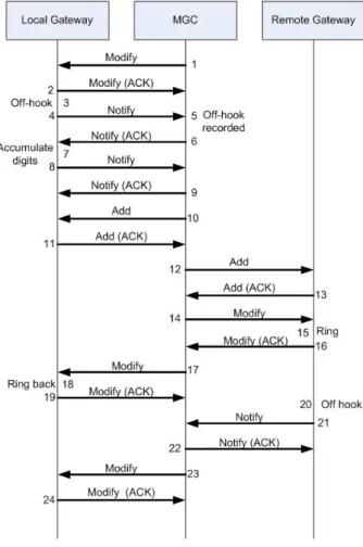
Protocol flow
Figure 2.9 shows the protocol flows for the setup of a call of Megaco. At the first part, the Off-hook state shows the Local Gateway would like to have a call. After accumulating the digits (the address of the Remote Gateway), the connection can be setup, which is noticed to the Remote Gateway by a Ring. After an acknowledgement, there is a Ring back at the Local Gateway. When the Remote Gateway reaches the Off-hook state, the call has been setup.
2.4.3 MGCP
The Media Gateway Control Protocol (MGCP) is published as RFC 3435, which obsoletes an earlier definition in RFC 2705 and integrates the Simple Gateway Control Protocol (SGMP) and the Internet Protocol Device Control (IPDC) specification. The Gateway Controller is called a Call Agent.
MGCP as primarily developed to address the demands of carrier-based IP telephone networks. MGCP is a complementary protocol for both H.323 and SIP, which was designed as an internal protocol between the Media Gateway Controller and the Media Gateway. In MGCP, an MGC primarily handles all the call processing by linking with the IP network through constant communications with an IP signaling device, for example an SIP Server or an H.323 gatekeeper.
Chapter 2. State of the art in VoIP 2.4. The Call Processing Protocols
Figure 2.9: Megaco protocol flow
Services
MGCP is comprised of a Call Agent, one media gateway (MG) which performs the conversion of media signals between circuits and packets, and one signaling gateway (SG) when connected to the PSTN (Public Switched Telephone Network). MGCP is widely used between elements of a decomposed multimedia gateway.
Call Agents come with the capability of creating new connections, or modify an existing connection. Generally, a media gateway is a network element which provides conversion between the data packets carried over the Internet or other packet networks and the voice signals carried by telephone lines. The Call Agent provides instructions to the endpoints to check for any events and - if there is any - create signals. The endpoints are designed in such a way as to automatically communicate changes in service state to the Call Agent. The Call Agent can audit endpoints and the connections on endpoints. [56]
MGCP uses the following commands [28]:
• AUEP - Audit Endpoint: Used by the Call agent to query (the state of) a Media Gateway
2.4. The Call Processing Protocols Chapter 2. State of the art in VoIP
• AUCX - Audit Connection: Used by the Call agent to query (the state of) a Media Gateway
• CRCX - Create Connection: Used by a Call Agent to manage an RTP connection on a Media Gateway
• DLCX - Delete Connection: A Media Gateway can also send a DLCX when it needs to delete a connection for its self-management
• MDCX - Modify Connection: Used by a Call Agent to manage an RTP connection on a Media Gateway
• RQNT - Request for Notification: Used by a Call Agent to request notification of events on the Media Gateway, and to request a Media Gateway to apply signals
• NTFY - Notify: Used by a Media Gateway to indicate to the Call Agent that it has detected an event for which the Call Agent had previously requested notification of
• RSIP - Restart In Progress: Used by a Media Gateway to indicate to the Call Agent that it is in the process of restarting
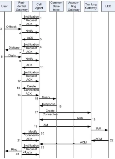
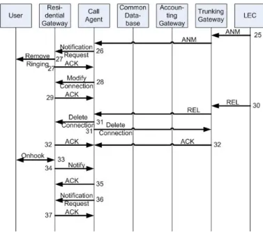
Protocol flow
Figures 2.10 and 2.11 shows the call setup and tear down of MGCP. The user starts the setup by starting the Off-hook state. He hears the dial tone and enters the digits (the address of the callee). When the connection is setup to the callee, the user hears a ringtone. When the user ends the connection, the on hook state is reached again.
2.4.4 SIP
The Session Initiation Protocol (SIP) [94] is a control protocol which can set up, modify and tear down sessions between session users. An interesting part of SIP is the support for mobility. If a user registers his or her location with a SIP server, SIP will direct SIP messages to the user or invoke a proxying operation to another server to a user’s current location. SIP can be used with UDP or TCP, which is in an intelligent way implemented: UDP will be used first. If problems arise and a timeout will happen, TCP will be used as a fallback. SIP is an attractive control tool for IP telephony because:
• It can operate as stateless or stateful. It provides good scalability and robustness for the stateless implementation.
• It uses many of the formats and syntax of HTTP, thus providing a convenient way of operating with ongoing browsers.
• The SIP message (the body) can be used in any syntax, such as Multipurpose Internet Mail Extension (MIME) or the Extensible Markup Language (XML).
• It identifies a user with a URI, thus providing the user the ability to initiate a call by clicking on a Web link.
Chapter 2. State of the art in VoIP 2.4. The Call Processing Protocols
Figure 2.10: MGCP protocol flow part 1
Services
SIP supports five aspects regarding the establishment and termination of communications sessions: [84]
• User location: Determination of the destination end system
• User availability: Determination of the willingness of the call party to accept a call to this device
• User capabilities: Negotiation of the session parameters
• Session setup: Establishment of the session
• Session management: Modification and termination of the session
A SIP architecture consists of three types of elements: SIP User Agents, SIP servers, and Location Servers. These elements are shown in Figure 2.12. SIP User Agents are end devices such as: SIP phones, a software SIP client on a computer or handheld, or a gateway to other networks, typically a PSTN gateway. They can originate SIP requests and send and receive
2.4. The Call Processing Protocols Chapter 2. State of the art in VoIP
Figure 2.11: MGCP protocol flow part 2
media. A SIP User Agent contains two parts: the User Agent Client (UAC) part initiates requests and the SIP User Agent Server (UAS) part responds to received requests.
Three types of SIP servers exists: Proxy, Redirect, or Registrar servers [94]. When receiving requests from a SIP user agent or a SIP proxy for a call setup, it forwards the requests towards the intended destination. A SIP Redirect server receives requests from User Agents or proxies and returns redirection information to contact an alternative URI. A SIP Registrar receives SIP registration requests and updates Location Servers with SIP User Agent information. A Location Server is a database that contains user, routing, and location information.
SIP uses several operations (according to RFC254 and RFC3261 [94]):
• ACK: Acknowledgement of a received message
• BYE: End of the session
• CANCEL: Cancellation of the request
• INVITE: Invitation of a user to a call
• OPTION: Request for information about the possibilities of the server
• REGISTER: Registration of the user agent
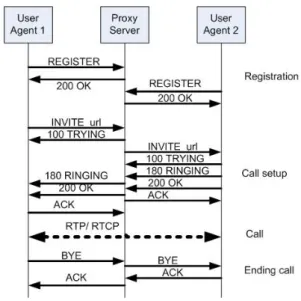
Protocol flow
Figure 2.13 shows an example of a complete SIP session, starting with the registration, fol-lowed by the call setup and the call and finishing with the ending of the call. The INVITE method is explained in more detail in Appendix A.
Chapter 2. State of the art in VoIP 2.5. The User Protocols
Figure 2.12: SIP elements
2.4.5 Summary
Table 2.1 shows an overview of the four Call Processing Protocols as described before. [81] [83]
2.5
The User Protocols
SIP is a protocol used to start up VoIP calls, not to send the actually desired data over the network. To send the data the User Protocol Real Time Protocol (RTP) and the Support Protocol ’Real Time Control Protocol’ (RTCP) are used.
2.5.1 Real Time Protocol (RTP)
The RTP standard defines a packet structure for use in real-time applications, amongst others it includes fields for timestamps and sequence numbers necessary for synchronization. RTP runs over UDP and is often viewed as a sub layer of the transport layer. However technically the RTP protocol is implemented in the application layer. Data encapsulation is performed at the end systems and the protocol does not provide any mechanism to prevent out of order packets or quality mechanisms. In order to provide control functions RTP is usually complemented with the RTCP protocol, described in the next section.
2.6
The Support Protocols
This section describes the support protocols Session Description Protocol (SDP), Network Time Protocol (NTP) and RTP Control Protocol (RTCP).
2.6. The Support Protocols Chapter 2. State of the art in VoIP
Figure 2.13: Possible protocol flow of SIP
2.6.1 RTP Control Protocol (RTCP)
The RTP control protocol (RTCP) is usually implemented in combination with the RTP protocol and is based on the periodic transmission of control packets. RTCP does not send a payload with application data, instead it sends statistical information that is necessary for the application to provide feedback on the VoIP quality. The way this information is used by the application layer is not defined in the RFC3550 standard, and depends strictly on the application. RTCP and RTP packets are distinguished by using different port numbers. Typically the RTCP port is one higher than the RTP port, RTCP also uses UDP as the transport protocol.
The statistical information RTCP gathers are for example information about loss, jitter, feedback and the round trip time. An application can use these information to increase the QoS, lower the bandwidth by using another bandwidth, or some thing else.
2.6.2 Session Description Protocol (SDP)
SDP is a text-based session description format. It is used by SIP to convey information about a media session, e.g. type of media, the transport protocol in use, format of the media, multicast addresses, port numbers, etc. [86]. SIP carries SDP encoded in MIME as a message body in a SIP message. SDP supports use of IPv6 addresses.
2.6.3 Network Time Protocol (NTP)
The Network Time Protocol (NTP) is a protocol for synchronizing the clocks of computer systems over packet-switched, variable-latency data networks. NTP uses UDP port 123 as its transport layer. It is designed particularly to resist the effects of variable latency. NTP is needed in VoIP for the QoS, if for instance the end-to-end delay is measured, the time should be synchronised.
Chapter 2. State of the art in VoIP 2.7. Conclusions
H.323 SIP MGCP MEGACO
Architectural Model Peer-to-peer Peer-to-Peer Master/slave Master/slave
Media types Voice, video,
limited data
Voice, video, data
Voice Voice, video
Network scope Intra, extra
and Internet
Inter, Extra and Internet
Intranet only Intranet only
Extensibility Low High Medium Medium
Scalability Medium High Low Low
Ease of deployment Low High Medium Medium
Standardization ITU-T IETF IETF IETF and
ITU-T Functionality Establishing connection Establishing connection Signaling Control Infor-mation Signaling Control Infor-mation
Advantages Quite
preva-lent and
powerful (es-pecially for conferencing)
Relatively sim-ple and eas-ily extensible. It is published as RFC 2543, thus a formal IETF standard Web-based and relatively sim-ple Web-based and relatively sim-ple
Disadvantages Complex built on ITU-T OSI layer 6 - Lots of redun-dancy relative to Megaco, but not an Internet standard
-Endpoints Smart Smart Dumb Dumb
Network Dumb Dumb Smart Smart
Table 2.1: Summary of the Internet Call Processing protocols
NTP is one of the oldest Internet protocols still in use (since before 1985). NTP was originally designed by Dave Mills of the University of Delaware, who still maintains it, along with a team of volunteers. NTP is published in RFC 1119.
NTP can operate above UDP or TCP. The time is displayed as GMT.
2.7
Conclusions
This chapter gave a short introduction to telephony and VoIP. Furthermore it provided in-formation about the Call Processing Protocols (H.323, MGCP, Megaco and SIP), the User Protocol (RTP) and the Support Protocols (RTCP, SDP and NTP). These different protocols are complementary; they offer the functionality of VoIP, although they cannot do the setup, tear down and actual call all by there self. The four Call Processing Protocols support the
2.7. Conclusions Chapter 2. State of the art in VoIP
call setup and tear down, but are different. H.323 and SIP have smart endpoints and a dumb network and Megaco and MGCP have dumb endpoints and a smart network. Hence, the protocols are not equal, and thus have to be translated to make the protocols compatible. SIP is an open and emerging protocol, unfortunately not all protocols used for VoIP are open. Proprietary protocols are not easily translated, and quite often are not possible to translate at all. This means it is not possible to interconnect all of the protocols and thus for the interconnection, a protocol independent solution should be found.
The next chapter shows the commonly used VoIP systems, and shows that the VoIP systems not always use the VoIP protocols as described in this chapter. Some of the VoIP systems use their own, proprietary protocols and are thus not open.
Chapter 3
Overview of VoIP Systems
Nowadays, many Instant Messenger (IM) and VoIP systems are available. Instant Messenger systems, which started with only messaging have voice calls included now. Examples of these systems are Live Messenger (MSN), Google Talk, Yahoo! Messenger and ICQ. The Skype system has entered the market with the audio as main target and is currently the market leader on VoIP.
Remember that in this report the term ”VoIP system” means that the system offers both IM and VoIP functionality.
This chapter provides an overview of the most widely used VoIP systems. Information on these VoIP systems are found in existing reports, papers and with experiments. These experiments are performed by the author of this report, by using Wireshark [70], which is an application to snif packets. Sequence diagrams are produced using Visual Ether [69] and are summarized in readable sequence diagrams by the author. Those latter sequence diagrams are published in Appendix B
Based on the existing VoIP systems, a generic system has been made to refer to. The overview of every VoIP system is divided into thee parts:
• Features
• Entities
• Protocol
The ’features’ paragraphs sum up the functionalities of the VoIP system and compare them to a generic list of functionalities. The ’entities’ paragraphs discuss the entities of the VoIP systems. The ’protocol’ paragraphs discuss the several protocols used by the VoIP system. The focus in this chapter will be on Login, Buddy search, Message sending and Calling. More information about File transfer can be found in Appendix B. Detailed information about the protocols of the VoIP systems, such as the protocol flows can also be found in Appendix B.
3.1
Aspects of VoIP systems
This chapter discusses several VoIP systems and compares them with a generic VoIP system, shown in the next sections. This generic VoIP system has been developed based on analyses
3.1. Aspects of VoIP systems Chapter 3. Overview of VoIP Systems
of all described VoIP systems. The reason for this generic VoIP system is to compare it to the existing VoIP systems, to show easily the differences, and similarities between the several VoIP systems and their accompanying protocols.
3.1.1 Features
The VoIP systems have many features. The main services of most VoIP systems are:
• Login: Authentication with username (name, email address or number) and password
• Buddy search: Every user has a contact list with one or more buddies. To expand this list, other contacts can be searched for and added. We only focus on the searching for a buddy and expanding of the contact list
• Messaging: Typing in a message and sending it to one or more selected user(s)
• Calling: Setting up a conversation requires first the invitation of the caller, which the callee might accept. After acceptance, the conversation starts. This report only focuses on PC-to-PC calls 3.1.2 Entities
VoIP system
User B
SAP BUser A
SAP AFigure 3.1: Entities of a VoIP system
Figure 3.1 shows an overview of a VoIP system. It is based on the five architectures of the VoIP systems discussed in this chapter. Each VoIP system has two users. A user only notices it is using the system to communicate with another user. He does not notice what is happening inside the system.
Figure 3.1 shows in between the users and the VoIP system Service Access Points (SAPs). These SAPs show the interactions between the VoIP system and the users. It defines the services.
Chapter 3. Overview of VoIP Systems 3.1. Aspects of VoIP systems Client A Client B ULL system VoIP system Server User A User B
Figure 3.2: Entities of a VoIP system
Figure 3.2 shows a decomposition of Figure 3.1. Inside the VoIP system, two clients, a server and an Underlying Layer (ULL) of the VoIP system are situated. The clients offer the interface to the user and use the ULL to send their data to the server or to other clients. The server consists of the Login Server and other servers, like a chat server or VoIP server. If the clients do not use the server to communicate with each other, they use a P2P connection. Login is always done with the use of a server. For the most VoIP systems, buddy search and messaging is done with the use of a server and Calling is done with a P2P connection.
3.1.3 Protocol
In this section we present the generic protocol flow in sequence diagrams. These generic protocol flows are based on the protocol flows of the five VoIP systems as discussed in this chapter. In the ’protocol’ sections of the VoIP systems, we show a short overview of the protocol(s) used by the VoIP system, the sequence diagrams are presented in Appendix B. Login
Figure 3.3 shows the generic login sequence diagram. First a secure connection has to be set up, before login to the server is possible. Afterwards, it is possible to login to other servers. Buddy search
Figure 3.4 shows the generic buddy search sequence diagram. First the client has to request for a buddy search. For some VoIP systems, a list of possible buddies is returned. This list contains the usernames that almost equal the search. In that case, one buddy has to be selected, in both cases Client B receives an addbuddy request. If Client B accepts, the selected buddy is added to the contact list of Client A.
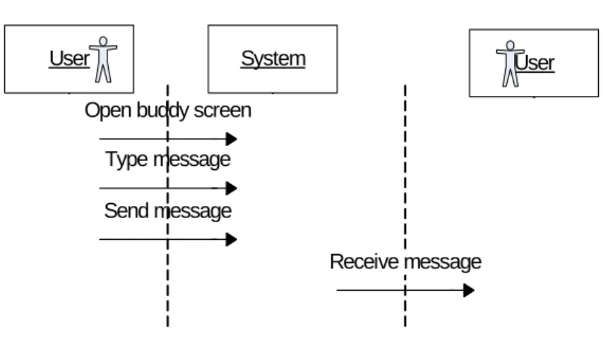
Messaging
3.1. Aspects of VoIP systems Chapter 3. Overview of VoIP Systems
Figure 3.3: Login sequence diagram
Figure 3.4: Buddy search sequence diagram
the user is typing. This is not a functionality offered by every VoIP system. Afterwards the message is sent and an acknowledgement is received in return.
Call
Figure 3.6 shows the generic call sequence diagram. First a request for a call is sent to Client B. If Client B accepts, the actual conversation takes place. Afterward both Client A and Client B are allowed to close the call, in this example Client A closes the call and Client B acknowledges it.
Chapter 3. Overview of VoIP Systems 3.1. Aspects of VoIP systems
Figure 3.5: Messaging sequence diagram
3.2. Windows Live Messenger (MSN) Chapter 3. Overview of VoIP Systems
3.2
Windows Live Messenger (MSN)
Windows Live messenger [32] (formerly known as MSN messenger) has been released by Microsoft on August 24, 1995, to coincide with the release of Windows 95. Windows messen-ger is a proprietary VoIP system installed on Windows XP and available for among others Windows 2000. This latter application, Windows Messenger should not be confused with the MSN messenger or Windows Live Messenger, although they have similar functionalities. MSN messenger has changed the name in 2006 to Windows Live Messenger. The word ”MSN” is the word for MSN Messenger and Windows Live Messenger in Internet slang [30]. In this report the word MSN will be used when Windows Live messenger or the older version MSN messenger is mentioned. Windows messenger has not been studied.
3.2.1 Features
MSN offers the main services and furthermore offline text messages for Windows Live Mes-senger, video communication, Multi-user chats, SMS, avatars and other personalization tools. It is also possible to make a call to a PSTN phone.
3.2.2 Entities
The architecture of MSN consists of servers and several clients and is thus a client-server architecture. Multiple servers are used and a peer-to-peer connection between two clients is possible.
MSN uses the following servers:
• Dispatch Server (DS)
• Notification Server (NS)
• Switchboard Server SS
The DS tracks locations for the notification servers and communicates the IP address of these servers to clients. The NS manages the user presence of the users. Clients must maintain connection to the NS at all times. The NS provides information on client locations for routing purposes and provides connections to the SSs. It provides presence information notifying other users if whether or not a particular user is connected. The SS provides messaging and file transfer functionality between two clients.
The .NET Passport Login Server is also part of the authentication process. In this report it can be seen as a part of the DS, to limit the amount of servers in the architecture and the sequence diagrams. The .NET Passport Login Server provides the client attempting to sign in with a ticket to complete the authentication process with a NS. Also the Nexus Server is a part of the DS in this report. The Nexus Server is another part of the authentication process and provides a client with a URL (Uniform Resource Locator) of the .NET Passport Login Server and information necessary to authenticate.
The DS can be accessed via the domain name messenger.hotmail.com. The function of the DS is to direct the user to an appropriate NS (based on the supplied .NET passport). If
Chapter 3. Overview of VoIP Systems 3.3. Google Talk
the messenger.hotmail.com domain name could not be reached (i.e. if the firewall blocks the port), the domain name gateway.messenger.hotmail.com is available for HTTP connections. The MSN client will often store the address of the appropriate NS once located, to make future connections go easier.
The NS manages user presence on the network. Logging in to the NS announces the avail-ability of the user. The NS stores and synchronizes user details, provides notifications of new Hotmail messages and checks the version of the MSN client being used. The NS does not handle IM, the NS will set up a connection to the SS for IM.
The SS establishes and manages chat sessions between users on the network. The SS forwards IM messages to the recipients. Users do not know each others IP address. The SS facilitates file transfers, but are carried out peer-to-peer using the MSN File Transfer Protocol (MSNFTP). After both users agree to send the file, SS provides IP addresses.
While connected to the SS, the user is still connected to the NS. If the NS connection is broken, the SS notices the offline status and will not allow the connection from the user to the SS anymore.
MSN uses Microsoft’s .NET Passport for creating and maintaining the user accounts. This account can be created at the Hotmail or .NET websites, not within the MSN domain. Once an account is created, it is possible to sign in to the MSN network directly.
3.2.3 Protocol
MSN uses the Mobile Status Notification Protocol (MSNP) for the login and the MSN Mes-senger Service (MSNMS) for the messaging. Furthermore, SIP is used for the call. The sequence diagrams of the main services are presented in Appendix B.3.
3.3
Google Talk
Google Talk (GTalk) [16] is an application offered by Google for VoIP and IM and is available since August 2005. Google’s mission is to make the world’s information universally accessi-ble and useful. GTalk uses the open protocol Extensiaccessi-ble Messaging and Presence Protocol (XMPP) and Jabber [23] for the IM part and presence events. To make VoIP, video and other peer-to-peer multimedia sessions possible, Google released libjingle [88] in December 2005. Libjingle is a library of the code that Google uses for peer-to-peer communication, and was made available under a BSD license. This license is like the GNU GPL license for free software, but with more restrictions.
GTalk does not encrypt the Jabber stream; it uses an undocumented nonstandard way of authenticating to the service, retrieving a token from a secure web server. Other clients than Google’s own are required to secure their streams with Transport Layer Security (TLS) before sending the password, causing them to stay encrypted throughout the whole session. GTalk claims to fully support encryption of chats and calls before their next official release. [9] [12] [11]