LIGHT-DRIVEN HYDRIDE TRANSFER FROM IRIDIUM HYDRIDE COMPLEXES
Seth M. Barrett
A dissertation submitted to the faculty at the University of North Carolina at Chapel Hill in partial fulfillment of the requirements for the degree of Doctor of Philosophy in the
Department of Chemistry.
Chapel Hill 2016
Approved by:
ii © 2016 Seth M. Barrett ALL RIGHTS RESERVED
ABSTRACT
Seth M. Barrett: Light-Driven Hydride Transfer from Iridium Hydride Complexes (Under the direction of Alexander J. M. Miller)
Light-triggered hydride transfer is an emerging class of chemical transformations that is increasingly being applied to systems previously promoted with elevated reaction temperatures. The excited state of [Cp*Ir(bpy)(H)]+ can drive chemical reactivity. The strength of the Ir-H bond can be determined through hydricity in both the ground and excited states to predict reactivity with substrates. Using thermochemical cycles, the excited state hydride is predicted to become a much stronger hydride donor, with nearly a 20 kcal·mol–1 enhancement in the
experimentally measured excited state hydricity compared to the ground state hydricity. Using [Cp*Ir(bpy)(H)]+ and 460 nm light, hydride transfer to methylnicotinamide results in the formation of singly and doubly reduced products. Notably, the doubly reduced product is traditionally formed using harsh reaction conditions. Instead, the doubly reduced product can be exclusively formed using visible light.
Moving beyond stoichiometric hydride transfer, [Cp*Ir(bpy)(H)]+ excited state reactivity can be applied to photocatalytic dehydrogenation of formic acid. By the careful study of a new [Cp*Ir(bpy-OMe)(H)]+ photocatalyst, the reaction mechanism can be better understood in order
iv
stable across a wide pH range, promoting the reaction at both acidic and basic pH. Between pH 7 – 11, 96% pure H2 is collected by trapping evolved CO2 in solution.
Catalytic hydrodehalogenation of dichloromethane is also promoted using the excited state reactivity of [Cp*Ir(bpy)(H)]+. A biphasic reaction setup allows for the in situ formation of the hydride catalyst, which is irradiated to form chloromethane-d2. Formate regenerates the
active hydride to promote catalytic turnover, with greater than 3 TON of chloromethane. UV-Vis reaction monitoring and kinetic analysis using the method of initial rates determines the
ACKNOWLEDGEMENTS
I first thank my family for all of their support and encouragement in graduate school and throughout my life. My parents, Mike and Carolyn, my sister Lindsey, my aunts Julia, Bobbi, and Weezie, and my uncle Michael have helped me more than I can ever convey. Thank you. I appreciate you always being there for me.
I must also thank my advisor, Alex Miller, for all his help, support, and knowledge during my time at UNC. I am grateful to you for giving me the chance to work in your lab and to continue my studies at UNC. I have learned so much and accomplished much more than I
thought was possible. To Joe Templeton, Cindy Schauer, and Maurice Brookhart: thank you for your encouragement and advice on a variety of issues, I greatly appreciate it.
vi
TABLE OF CONTENTS
LIST OF FIGURES ... ix
LIST OF TABLES ... xvi
LIST OF SCHEMES... xvii
LIST OF EQUATIONS ... xix
LIST OF SYMBOLS AND ABBREVIATIONS ... xxi
Chapter 1: TRANSITION METAL COMPLEXES: FROM THERMAL REACTIVITY TO PHOTOCHEMICAL ROUTES ... 1
1.1 Introduction to Cp*Ir Reactivity ... 1
1.2 Hydricity ... 4
1.3 Formic Acid Dehydrogenation ... 9
1.4 Hydrodehalogenation Reactions ... 19
1.5 REFERENCES ... 30
Chapter 2: PHOTOSWITCHABLE HYDRIDE TRANSFER FROM IRIDIUM TO 1-METHYLNICOTINAMIDE RATIONALIZED BY THEROCHEMICAL CYCLES ... 37
2.2 Results and Discussion ... 38
2.3 Conclusions ... 47
2.4 Experimental Section ... 48
2.5 Acknowledgements ... 67
2.6 Associated Content ... 67
2.7 REFERENCES ... 68
Chapter 3: PHOTOCHEMICAL FORMIC ACID DEHYDROGENATION BY IRIDIUM COMPLEXES: UNDERSTANDING MECHANISM AND OVERCOMING DEACTIVATION... 72
3.1 Introduction ... 72
3.2 Results and Discussion ... 74
3.3 Conclusions ... 88
3.4 Experimental Section ... 89
3.5 Acknowledgements ... 105
3.6 Associated Content ... 105
3.7 REFERENCES ... 106
viii
4.1 Introduction ... 109
4.2 Results and Discussion ... 112
4.3 Conclusions ... 124
4.4 Experimental Section ... 125
4.5 Acknowledgements ... 131
4.6 Associated Content ... 131
4.7 REFERENCES ... 132
APPENDIX A. PHOTOSWITCHABLE HYDRIDE TRANSFER FROM IRIDIUM TO 1-METHYLNICOTINAMIDE BY THERMOCHEMICAL CYCLES ... 136
APPENDIX B. PHOTOCHEMICAL FORMIC ACID DEHYDROGENATION BY IRIDIUM COMPLEXS: UNDERSTANDING MECHANISM AND OVERCOMING DEACTIVATION... 158
LIST OF FIGURES
Figure 1.1. Hydricity scale in acetonitrile. Stronger hydride donors are found to the right of the scale. ... 7 Figure 1.2. DOE strategies towards physical and materials-based hydrogen storage
materials.91 ... 10 Figure 1.3. Mechanistic study with [Cp*Ir(bpy-R)(OH2)]2+ precatalyst under varying H2 and
CO2 pressures. The in situ generated hydride was observed and the following carboxylation
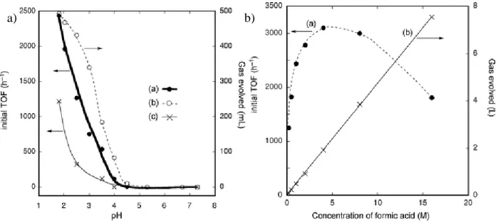
step was determined to be rate limiting.7 ... 11 Figure 1.4. a) Effect of pH and b) formic acid concentration on catalytic activity towards
thermal formic acid dehydrogenation.19 ... 14 Figure 1.5. Precatalyst [(Cp*IrCl)2(thbpym)]2+ towards reversible formic acid
dehydrogenation. ... 15 Figure 2.1. Structural representation of 4 (ellipsoids at 50% probability). Three PF6 ions, two
CH3CN molecules, and H atoms omitted for clarity. A H-bond between one CH3CN and the
imine NH is observed (N-N: 3.201 Å).12 Selected bond distances (Å) and angles (º): Ir1–N1 2.149, Ir2–C1 2.126, N1–C1 1.245, C1–C2 1.503, Ir1–N1–C1 131.8, Ir2–C1–N1 119.7, Ir2–C1–C2 129.5... 44 Figure 3.1. Gas evolution from formate solutions of 1 (filled circles), 1-OMe (empty squares), and no catalyst (empty circles) during intermittent illumination (white background: lamp on, gray background: lamp off). Conditions: 0.32 mM Ir, pH 10 1 M NaCO2H(aq), 18 mM
phosphate, 296 K. ... 75 Figure 3.2. a) H2 content of evolved gas as a function of pH for 1 (filled circles) and 1-OMe
(empty squares). b) Initial TOF (H2 over 2 h) as a function of initial pH for 1 (filled circles)
and 1-OMe (empty squares). Conditions: 0.36 mM catalyst, 1 M NaCO2H(aq), 296 K. ... 77
Figure 3.3. a) Gas volume measured from the eudiometer after 2 h irradiation with varying concentrations of precatalyst 1-OMe in pH 9 1 M formate. b) Gas evolved after 2 h of 460 nm irradiation of 0.36 mM 1 (filled circles) and 0.36 mM 1-OMe (empty squares) with varying concentrations of formate at pH 9. ... 79 Figure 3.4. Absorbance profile after injection of 0.36 mM 1-OMe into pH 9 1 M NaCO2H(aq)
x
compared to initial pH measured before the reaction. Conditions: 0.18 – 1.50 mM 1 or 1-OMe, 0.5 – 4 M NaCO2H(aq), 296 K, 0 – 36 mM phosphate, 0 – 4 mM free ligand. ... 95
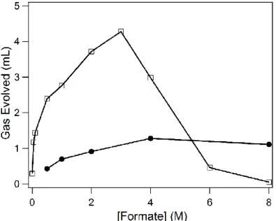
Figure 3.6. Gas evolved after 2 h of 460 nm irradiation with varying concentrations of
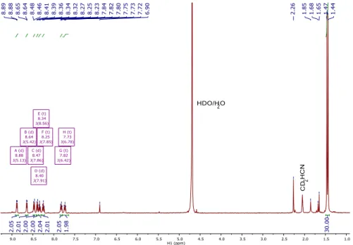
formate with 1 (filled circles) and 1-OMe (empty squares). ... 101 Figure 4.1. 1H NMR spectrum of [Cp*Ir(bpy)(H)][OTf](2)in a CD
2Cl2/H2O biphasic system
in a) the initial dark tube b) the dark tube after 1 hour, c) the initial light tube, and d) the light tube after irradiation with 460 nm LED for 1 hour. CD2HCl peak growth is observed
at δ 2.99. ... 113 Figure 4.2. Absorbance profile of 0.56 mM 1 in CH2Cl2 upon 443 nm irradiation to
form 1-Cl (and chloromethane). The growth of 1-Cl was observed between 0.15 – 30 min of irradiation... 116
Figure 4.3. UV-Vis spectra of 0.21 mM 1 and 0.21 mM 1-Cl. ... 117 Figure 4.4. a) Log plot of quantum yield vs. [1] using 443 nm irradiation at 250 mA current and b) log plot of quantum yield vs. [1] using 443 nm irradiation at 10 mA current. ... 117 Figure 4.5. Changes in concentration of [1] vs. quantum yield of the reaction. Irradiated with 443 nm LED at 10 mA current. ... 119 Figure 4.6. Plot of quantum yield vs. [1] using 443 nm irradiation at 10 mA current with the addition of 0.1 M tetrabutylammonium electrolyte. ... 121 Figure 4.7. Biphasic reaction setup consisting of an aqueous formate layer and an organic
CD2Cl2 layer in an NMR tube. A foil mask is used to prevent photolysis of the aqueous layer.
Hydride 1 quickly forms in the aqueous formate layer from precatalyst 1-Cl, then moves to the organic layer and is photolyzed to produce chloromethane and regenerate precatalyst 1-Cl. Conditions: 9.4 mM 1-Cl, 1.1 M NaCO2H, 296 K, 443 or 460 nm irradiation... 122
Figure 4.8. Photon flux measurements for the 443 nm ThorLabs LED lamp at varied current using the potassium ferrioxalate chemical actinometer. ... 129 Figure 4.9. 1H NMR spectrum of [Cp*Ir(bpy-OMe)(H)][OTf]in a biphasic setup with
CD2Cl2 and H2O after irradiation with 460 nm LED. CD2HCl peak growth is observed after
2, 5, and 12 hours of irradiation. Spectra normalized to mesitylene internal standard. ... 131 Figure A.1. 1H NMR spectrum of [Cp*Ir(bpy)(H)][OTf] (1) in CD3CN. ... 136
Figure A.2. 1H NMR spectrum of [Cp*Ir(bpy)(NCCH3)][PF6] (2)in CD3CN. ... 136
Figure A.3. 13C(1H) NMR spectrum of [Cp*Ir(bpy)(NCCH
3)][PF6] (2) in CD3CN... 137
Figure A.5. 13C(1H) NMR spectrum of [Cp*Ir(bpy)(OAc)][OAc] (3)in CD3CN. ... 138
Figure A.6. 1H NMR spectrum of 4-OTf in CD
3CN containing mesitylene internal standard
(δ 6.90, 2.26). ... 138 Figure A.7. 1H NMR spectrum of [Cp*Ir(bpy)(µ-N(H)C(CH3))(bpy)IrCp*][PF6]3 (4-PF6)
in CD3CN. ... 139
Figure A.8. 13C(1H) NMR spectrum of [Cp*Ir(bpy)(µ-N(H)C(CH3))(bpy)IrCp*][PF6]3
(4-PF6) in CD3CN. ... 139
Figure A.9. IR spectrum of [Cp*Ir(bpy)(µ-N(H)C(CH3))(bpy)IrCp*][PF6]3 (4-PF6). P-F
stretch dominates the spectrum (826 and 555 cm-1). C=N = 1536 cm-1. ... 140
Figure A.10. UV-Vis spectra monitoring addition of DBU to 1 in CH3CN. ... 140
Figure A.11. Plot of ([Ir]t/[IrH]t)*[HDBU]t vs [DBU]t generated from data points
at 620 nm... 141 Figure A.12. 1H NMR spectrum of methanesulfonic acid and 1 in CD3CN after 1 h in the
dark. The Cp* peak for 1 (δ 1.83) is notably absent, while the Cp* peak for the product (2) is seen (δ 1.67). Mesitylene (δ 6.80, 2.24), excess methanesulfonic acid (δ 8.01, 2.93), and hydrogen (δ 4.57) are also observed. ... 141 Figure A.13. 1H NMR spectra of pyridinium and 1 in CD3CN after 1 h in the dark (black) and
after 1 h of irradiation (blue). The Cp* peak for 1 (δ 1.83) is notably absent after irradiation, while the Cp* peak for the product is seen (δ 1.55). Mesitylene (δ 6.79, 2.23), excess
pyridinium (δ 8.77, 8.43, 7.91), and dihydrogen (δ 4.57) are also observed. ... 142 Figure A.14. 1H NMR spectra of pyridinium and 1 in CD
3CN after ~10 min in the dark
(black) and after heating at 80 ºC for 3 h in the dark (blue). Inset: 1H NMR spectra (Cp* region). ... 142 Figure A.15. 1H NMR spectra of triethylammonium and 1 in CD
3CN after 10 min in the dark
(black) and after 10 min of irradiation (blue). The Cp* peak for 1 (δ 1.83) is nearly absent, while the Cp* peak for the product (2) is seen (δ 1.68). Mesitylene (δ 6.79, 2.24), excess
triethylammonium (δ 3.10, 1.23), and dihydrogen (δ 4.57) are also observed. ... 143 Figure A.16. 1H NMR spectra of acetic acid and 1 in CD3CN after 10 min in the dark (black)
and after 10 min of irradiation (blue). The Cp* peak for 1 (δ 1.83) is nearly absent, while the Cp* peak for the product (3) is seen (δ 1.62). Mesitylene (δ 6.80, 2.24), excess acetic acid (δ 1.96), and dihydrogen (δ 4.57) are also observed. ... 143 Figure A.17. 1H NMR spectrum of 1 and [MNA][BF4] (1:1.7) in CD3CN after 1 h in the dark
xii
Cp* peaks for the products [Cp*Ir(bpy)(MNA)]2+ (δ 1.69) and 4-OTf (δ 1.41, 1.39) are observed. The methyl peak for [Cp*Ir(bpy)(MNA)]2+ is also seen (δ 4.18). Products
MNA-H, MNA-H', and MNA-H3 are labeled above as H, H', and H3, respectively. ... 144
Figure A.18. 1H NMR spectrum of 1 and [MNA][I] (1:1.5) in CD3CN after 1 h in the dark
(black) and after 3 min of irradiation (blue). Inset: the Cp* peak for 1 (δ 1.83) is significantly diminished, while the Cp* peak for the product [Cp*Ir(bpy)(I)]+ (δ 1.74), is observed. N-methyl group of products MNA-H, MNA-H', and MNA-H3 are labeled above as H, H',
and H3... 144
Figure A.19. 1H NMR spectrum of 1 and [MNA][I] (1:1.5) in CD3CN after 0, 3, 10, 20, and
60 min of irradiation. N-methyl group of products MNA-H, MNA-H', and MNA-H3 are
labeled above as H, H', and H3, respectively. ... 145
Figure A.20. Left: concentration of MNA-containing species as a function of photolysis time. Right: concentration of Ir-containing products as a function of photolysis time. ... 145 Figure A.21. 1H NMR spectrum of 1 and [MNA][I] (1:4.4) in CD3CN after 0, 10, 20, and 60
min of irradiation. N-methyl groups of products MNA-H, MNA-H', and MNA-H3 are
labeled above as H, H', and H3, respectively. ... 147
Figure A.22. Left: concentration of MNA-containing species as a function of photolysis time. Right: concentration of Ir-containing products as a function of photolysis time. ... 147 Figure A.23. 1H NMR spectrum of 1 and [MNA][I] (4.0:1) in CD3CN after 0, 10, 20, and 60
min of irradiation. N-methyl groups of products MNA-H, MNA-H', and MNA-H3 are
labeled as H, H', and H3, respectively. ... 149
Figure A.24. Left: concentration of MNA-containing species as a function of photolysis time. Right: concentration of Ir-containing products as a function of photolysis time. ... 149 Figure A.25. GC trace of 0.15 mL injected headspace from NMR tube of 1 and HOAc
following 20 min irradiation time. From the H2 calibration curve and integral of the H2 peak,
H2 yield was calculated to be 74%. ... 151
Figure A.26. Structural representation of 4 (ellipsoids at 50% probability) with a H-bonding interaction between N1−N6 (3.201 Å) from CH3CN solvent. Three PF6 ions, one CH3CN
molecule, and H atoms omitted for clarity... 152 Figure B.1. Experimental set-up for gas-volume measurements using the inverted-burette style eudiometer. The reaction vial (right) is irradiated while evolved gases are collected in the eudiometer (left) using the PTFE tubing... 158 Figure B.2. Pressure vessel containing 20 mL of 1 M formate solution with 1-OMe.
Figure B.3. Standard curve for H2 on the Varian 450-GC. ... 159
Figure B.4. Standard curve for CO2 on the Varian 450-GC. ... 159
Figure B.5. Chromatogram showing evolved H2 (0.6 min) and evolved CO2 (7.1 min) for a
sample after irradiation (O2 and N2 shown at 1.4 and 1.5 min, respectively). Conditions:
0.36 mM 1, 1.0 M formate, pH 10.5. This sample was calculated to be 96.1% H2. ... 160
Figure B.6. Gas volume measured from the eudiometer over 2 h irradiation with precatalyst 1-OMe (empty squares), no-precatalyst control (empty triangles), and [Cp*Ir(OH2)3]2+
(empty circles). ... 160 Figure B.7. H2 content of evolved gas as a function of pH for 1 and 1-OMe under a wide
variety of reaction conditions. a) 1 (filled circles) and 1-OMe (empty squares) with error bars. For small data sets, error bars were assigned based upon the average deviation for all data sets. b) 1 and 1-OMe both displayed as filled circles. Conditions: 0.18 – 1.50 mM 1 or 1-OMe, 0.5 – 4 M NaCO2H (aq), room temperature, 0 – 36 mM phosphate, 0 – 4 mM free
ligand... 161 Figure B.8. Gas volume measured from the eudiometer after 2 h irradiation with precatalyst 1 (filled circles) and no-precatalyst control (empty circles). ... 162 Figure B.9. Gas volume measured from the eudiometer after 2 h irradiation with precatalyst 1-OMe... 162 Figure B.10. Gas volume measured from the eudiometer after 2 h irradiation with varying
concentrations of precatalyst 1... 163 Figure B.11. Gas volume measured from the eudiometer after 2 h irradiation with varying
concentrations of precatalyst 1-OMe. ... 163 Figure B.12. In situ hydride formation monitored via UV-Vis in the dark starting from
precatalyst 1-OMe in 1 M formate. ... 164 Figure B.13. In situ hydride formation monitored via UV-Vis in the dark starting from
precatalyst 1-OMe in 1 M formate, followed by 460 nm irradiation. ... 164 Figure B.14. Gas evolution traces over 2 h starting from precatalyst 1-OMe in 1 M
HCO2H/H2O and DCO2D/D2O with 460 nm irradiation. ... 165
Figure B.15. Gas evolution traces over 2 h starting from precatalyst 1-OMe in 1 M
HCO2H/H2O and DCO2D/D2O with 460 nm irradiation. ... 165
Figure B.16. Gas evolution traces over 2 h starting from precatalyst 1-OMe in 1 M
xiv
Figure B.17. Spectral overlap between [Cp*Ir(bpy-OMe)(H)]+ (2-OMe) and 406, 443, 460, and 503 nm LED sources. ... 166 Figure B.18. TOF values from pressure vessel experiments with 1-OMe under 2 h
irradiation using 406, 443, and 503 nm LED sources... 167 Figure B.19. TOF values after 2 h of 443 nm irradiation at different power densities with 1-OMe. The dotted line is extrapolated from the first three data points. ... 167 Figure B.20. Time course of catalyst TON (filled circles) and TOF (empty circles).
Conditions: 0.37 mM precatalyst 1, 1.0 M formate, pH 10.2, 25 eq. phosphate. The color of the trace corresponds to the color of the axis. ... 168 Figure B.21. Photocatalytic H2 evolution activity of 1 alone (filled circles) and 1 in the
presence of 3 equivalents bipyridine (empty squares). Conditions: 0.36 mM 1, pH 9 1 M NaCO2H(aq), 296 K... 168
Figure B.22. After 20 h irradiation, Left: 1 without excess free ligand and Right: 1 with excess free ligand. ... 169 Figure B.23. 1H NMR spectrum in CD3CN after collecting [Cp*Ir(bpy-OMe)(H)][O2CH]
precipitate from mixing 1-OMe in 8 M formate. ... 169 Figure B.24. IR spectrum of [Cp*Ir(bpy-OMe)(H)][O2CH] precipitate from mixing 1-OMe
in 8 M formate. O-H stretch (3350 cm−1) from water, and C-O stretch (1586 cm−1)
dominate the spectrum. Ir-H stretch seen at 2046 cm−1. ... 170 Figure B.25. 1H NMR spectrum of [Cp*Ir(bpy)(H)][O2CH] in D2O from mixing 1 in 8 M
formate. ... 170 Figure B.26. 1H NMR spectrum of chloride 1 and aquo [Cp*Ir(bpy)(H2O)]2+ in pH 9.6
carbonate buffer. ... 171 Figure B.27. UV-Vis spectrum of 1 after prolonged 460 nm irradiation... 171 Figure B.28. Maximum TON runs for 1 and 1-OMe using 460 nm irradiation. ... 172 Figure B.29. Maximum TON runs for 1-OMe using 406 (purple) and 443 (blue) nm
irradiation. ... 172 Figure B.30. Maximum TON runs for 1 and 1-OMe using 443 nm irradiation. ... 173 Figure B.31. Headspace sampling technique for pressure vessel using a balloon. Left:
pressure vessel closed. Right: pressure vessel open. ... 173 Figure C.1. 1H NMR spectrum of [Cp*Ir(bpy-OMe)(H
Figure C.2. 1H NMR spectrum of [Cp*Ir(bpy-OMe)(H)][OTf]in DMSO-d6. ... 174
Figure C.3. 1H NMR spectrum of [Cp*Ir(bpy-OMe)(D)][PF
6]in CD3CN... 175
xvi
LIST OF TABLES
Table 1.1. [(Cp*IrCl)2(thbpym)]2+ precatalyst and recyclability towards CO2 hydrogenation
and formic acid dehydrogenation, demonstrated by concertation of formate and formic acid.
Adapted from ref.22 ... 15
Table 2.1. Visible light-promoted hydride transfer from [Cp*Ir(bpy)(H)][OTf] (1) to [MNA][I].a ... 46
Table 2.2. Quantum yield for visible light-promoted hydride transfer reactions from [Cp*Ir(bpy)(H)]+ to MNA+.a ... 66
Table 3.1. Kinetic isotope effects of photochemical dehydrogenation.a ... 81
Table 3.2. Absorption characteristics of 2-OMe during catalysis. ... 99
Table 3.3. Quantum yield of formate dehydrogenation catalysis by 1-OMe.a ... 100
Table 4.1. Effect of Electrolyte on Quantum Yield ... 120
Table A.1. Visible light-promoted hydride transfer from [Cp*Ir(bpy)(H)]+ to MNA+ (1:1.5).a ... 146
Table A.2. Visible light-promoted hydride transfer from [Cp*Ir(bpy)(H)]+ to MNA+ (1:4.4).a ... 148
Table A.3. Visible light-promoted hydride transfer from [Cp*Ir(bpy)(H)]+ to MNA+ (4.0:1).a ... 150
Table A.4. Quantum yield for visible light-promoted hydride transfer reactions from [Cp*Ir(bpy)(H)]+ to MNA+.a ... 151
Table A.5. Crystal Data and structure refinement for 4-PF6 [sb106_c]. ... 152
Table A.6. Bond Lengths for 4-PF6 [sb106_c]. ... 153
LIST OF SCHEMES
Scheme 1.1 Proposed mechanism of formation for [Cp*Ir(bpy)(H)]+ through β-hydride
elimination and release of CO2 upon reaction with formate.30 ... 3
Scheme 1.2. Potential-pKa method to determine hydricity. Adapted from ref.80 ... 6
Scheme 1.3. Relative hydricity from equilibrium using a reference hydricity value. Adapted from ref.80 ... 6
Scheme 1.4. Acid reactivity to determine hydricity. ... 6
Scheme 1.5. Aqueous hydricity determination through equilibrium in water.81 ... 8
Scheme 1.6. Thermochemical cycles for determination of excited state hydricity. ... 9
Scheme 1.7. Reversible H2 storage using the formate/bicarbonate couple for storage and production of H2. Adapted from ref.86 ... 11
Scheme 1.8. Cp*Ir and Rh catalysts towards CO2 hydrogenation. Adapted from ref.5 ... 13
Scheme 1.9. Hydrogenation of CO2 (bicarbonate) can be promoted using Cp*Ir in the dark, storing H2, while dehydrogenation of formic acid can be promoted with light. ... 16
Scheme 1.10. Photochemical dehydrogenation of formic acid using [Cp*Ir(bpy-R)(Cl)]+ precatalysts and visible light. R = COOH, NO2, NMe2. ... 18
Scheme 1.11. General hydrodehalogenation scheme with aromatic and aliphatic substrates. ... 19
Scheme 1.12. Proposed transition state of the hydrodehalogenation of 2-bromopropanoic acid using [Cp*Ir(bpy)(H)]+. Adapted from ref.30 ... 20
Scheme 1.13. Proposed radical chain mechanism for the hydrodehalogenation of aliphatic substrates using Cp*2ZrH2. Adapted from ref.114 ... 21
Scheme 1.14. Proposed direct hydridic attach mechanism for the hydrodehalogenation of aromatic substrates using Cp*2ZrH2. Adapted from ref.114 ... 22
Scheme 1.15. Proposed reaction scheme for the hydrodehalogenation of geminal dihalides using a NiI/NiII-H catalyst combination. Adapted from ref.123 ... 23
xviii
Scheme 1.17. Deuterium incorporation test to determine the hydrogen source in the
hydrodehalogenation reaction. Adapted from ref.123 ... 24
Scheme 1.18. Hydrodehalogenation of phenacyl bromide using AcrH2 electron donor, Ru(bpy)32+ photosensitizer, and 452 nm light. Adapted from ref.110 ... 25
Scheme 1.19. Reductive quenching mechanism for the hydrodehalogenation of phenacyl halide in the absence of HClO4. Adapted from ref.110 ... 25
Scheme 1.20. Oxidative quenching mechanism for the hydrodehalogenation of phenacyl halide in the presence of HClO4. Adapted from ref.110 ... 26
Scheme 1.21. Photoredox catalysis towards hydrodehalogenation for a variety of α-halides to carbonyls or aryl groups. Adapted from ref.111 ... 27
Scheme 1.22. Proposed mechanism towards reductive hydrodehalogenation of α-halides to carbonyls or aryl groups. Adapted from ref.48, 111 ... 28
Scheme 2.1. Hydricity of Complex 1. ... 39
Scheme 2.2. “Cube scheme” diagram showing thermochemical relationships between excited state and ground state species. In the scheme above, Ir represents Cp*Ir(bpy). ... 41
Scheme 2.3. Reactivity of Complex 1 with Organic Acids. ... 42
Scheme 2.4. Formation of Iminoacyl Complex. ... 43
Scheme 2.5. Proposed mechanism for the formation of 4. ... 45
Scheme 3.1. Typical conditions for photochemical formic acid dehydrogenation by 1 and 1-OMe... 74
Scheme 3.2. Proposed mechanism of photochemical formic acid dehydrogenation. ... 84
Scheme 4.1. General hydrodehalogenation reaction of a) aromatic and b) aliphatic halides. ... 109
Scheme 4.2. Reaction of [Cp*Ir(bpy-OMe)(H)][OTf]and CH2Cl2 with visible light. ... 112
Scheme 4.3. Iminoacyl formation from 2 in CD3CN in the presence of other substrates ... 115
LIST OF EQUATIONS
Equation 1.1………. 4
Equation 1.2………. 5
Equation 1.3………. 5
Equation 1.4………. 5
Equation 1.5………... 10
Equation 2.1……… .. 39
Equation 2.2……… .. 40
Equation 2.3………... 40
Equation 2.4………... 40
Equation 2.5………... 40
Equation 2.6……… .. 40
Equation 2.7………... 53
Equation 2.8……… .. 53
Equation 2.9………... 53
Equation 2.10………. 53
Equation 2.11………. 54
Equation 2.12………. 54
Equation 2.13………. 54
Equation 2.14………. 55
Equation 2.15………. 55
Equation 2.16………. 55
xx
Equation 2.19………. 56
Equation 2.20………. ... 56
Equation 2.21……….. ... 56
Equation 2.22……… ... 56
Equation 2.23………. ... 56
Equation 2.24………. 56
Equation 2.25……….. ... 57
Equation 2.26……….. ... 57
Equation 2.27……… ... 57
Equation 2.28………. ... 57
Equation 2.29………. ... 57
Equation 2.30………. ... 57
Equation 2.31……… ... 57
Equation 2.32……….. ... 58
Equation 2.33……… ... 58
Equation 2.34………. ... 58
Equation 3.1……… ... 72
Equation 3.2 ... 76
Equation 4.1……… ... 119
Equation 4.2……….. ... 119
Equation 4.3………. ... 119
Equation 4.4……… ... 119
Equation 4.5……….. ... 119
LIST OF SYMBOLS AND ABBREVIATIONS
dppe 1,2-bis-(diphenyl-phosphino)ethane) phen 1,10-phenanthroline
ppy 2-phenylpyridine tpy 2,2’:6’2”-terpyridine bpy 2,2’-bipyridine
TEMPO (2,2,6,6-Tetramethylpiperidin-1-yl)oxyl thbpym 4,4’,6,6’-tetrahydroxy-2,2’-bipyrimidine AcrH2 9,10-dihydro-10-methylacridine
A Absorbance
Å Angstrom
OAc Acetate HOAc Acetic acid
Ka Acid dissociation constant AcrH+ Acridinium
aq Aqueous
atm Atmosphere
BD4- Borodeuteride
BH4- Borohydride
11B Boron NMR
cal Calories
13C Carbon NMR
xxii
C Celsius
CV Cyclic voltammetry
o Degree
D Deuterium
DMF Dimethylformamide
e- Electron
ESI Electrospray ionization
E00 Energy difference between lowest vibration states of ground and excited state
OEt Ethoxy
Ka* Excited state acid dissociation constant Eo Formal potential
HCO2- Formate
HCO2H Formic acid
ΔGH+ Free energy, acidity ΔGH• Free energy, homolysis ΔGH- Free energy, hydricity
g Gram
GC Gas chromatography
E1/2 Half wave potential
Hz Hertz
PF6- Hexafluorophosphate
h Hour
Ir-H Iridium-hydrogen bond
J Joule
KIE Kinetic isotope effect LED Light emitting diode hv Light irradiation
LMCT Ligand to metal charge transfer
MS Mass spectrometry
M-H Metal-hydrogen bond
MLCT Metal to ligand charge transfer
OMe Methoxy
MNA+ Methylnicotinamide
µL Microliter
mg Milligram
mL Milliliter
mM Millimolar
mmol Millimole
min Minute
M Molar
ԑ Molar extinction coefficient
Mol Mole
nm Nanometer
NP Nanoparticle
xxiv NMR Nuclear magnetic resonance
R Organic subsituent
ppm Parts per million
Pa Pascal
Cp* Pentamethylcyclopentadienyl
31P Phosphorous NMR
PTFE Polytetrafluoroethylene KOH Potassium hydroxide
1H Proton NMR
Hpy Pyridinium
QY Quantum yield (as a decimal)
• Radical
s Second
TBA+ Tetrabutylammonium
TMEDA Tetramethylethylenendiamine HBEt3- Triethylborohydride
TOF Turnover frequency TON Turnover number OTf- Triflate
PPh3 Triphenylphosphine
OTs- Tosylate
UV Ultraviolet
W Watt
λ Wavelength
cm-1 Wavelength, inverse centimeters λmax Wavelength maximum
1
Chapter 1:TRANSITION METAL COMPLEXES: FROM THERMAL REACTIVITY TO PHOTOCHEMICAL ROUTES
1.1 Introduction to Cp*Ir Reactivity
Transition metal complexes have long been studied for their ability to promote chemical transformations, including hydride transfer, hydrogenation, and dehydrogenation.
Pentamethylcyclopentadienyl (Cp*Ir) iridium bipyridine (bpy) complexes have been used to catalyze a variety of chemical transformations since their discovery in 1988 by Ziessel,1 building upon similar catalysts from Maitlis and Crabtree.2, 3 The Cp*Ir complexes have been utilized in several transformations, including hydrogenation, 4-17 dehydrogenation,18-29 and
dehalogenation.30 The reactivity of Cp*Ir catalysts has been attributed to a reactive hydride intermediate.1, 31-35 Importantly, catalysis has been promoted primarily using thermal methods,
but emerging reports of photochemical reactivity motivate the development of new directions while also identifying potential areas for improvement. Specific, prominent examples of these transformations will be explored in more detail below.
Toward hydrogenation using Cp*Ir catalysts, perhaps one of the most highlighted transformations is the conversion of carbonyl functional groups to alcohol groups.36, 37 Cp*Ir
complexes have also been used to promote hydride transfer from biological cofactor
using NADH as the hydride donor.37 Similar reactions performed with sodium formate as the hydrogen source exhibited shorter reaction times. Catalytic transfer hydrogenation was also applied to an array of aldehydes and ketones, with near quantitative yields (up to 99%) for many substrates. Carbonate and CO2 hydrogenation has also been promoted with Cp*Ir-based
complexes,5-7, 9, 20, 22, 23, 40-47 with up to 222,000 TON and 42,000 h-1 TOF using [Cp*Ir(phen-OH)(Cl)]+ (phen-OH is 4,7-dihydroxy-1,10-phenanthroline) and [Cp*Ir(bpy-OH)(Cl)]+ (bpy-OH is 4,4’-dihydroxy-2,2’-bipyridine) catalysts.8, 9, 43
Dehydrogenation reactions have also been catalyzed using Cp*Ir complexes.18-29 Formic acid dehydrogenation has been reported, where Cp*Ir complexes have been used at elevated temperatures to achieve catalytic turnover.19 The volume of H2 and CO2 gaseous products could
be controlled by temperature, with greater performance at high temperatures. The reaction can also be controlled by pH, as more acidic solutions exhibited dramatically improved performance (consistent with the pKa of formic acid, 3.8). For example, [Cp*Ir(bpy-OH)(OH2)]2+ was found to
catalyze the dehydrogenation of 1 M formic acid in acidic water (pH 2.5-4).19
Hydrodehalogenations are useful synthetic transformations important to selective organic synthesis48 and decontamination of halogenated species in water sources.49-60 While
hydrodehalogenation activity for other transition metal hydride complexes have been reported, Cp*Ir activity towards hydrodehalogenation has not been well explored. One of the few reports of Cp*Ir-promoted activity includes the hydrodehalogenation of bromo- and chloropropanoic acid substrates in water.
In hydrogenation, dehydrogenation, and hydrodehalogenation reactivity, an in situ
generated hydride is traditionally proposed as the catalytic intermediate.7, 11, 30, 61-64 Ogo and
3
and structural determination of the hydride was made possible through reaction of the aquo precursor in pH 5 aqueous formic acid to yield the hydride species.61
Scheme 1.1 Proposed mechanism of formation for [Cp*Ir(bpy)(H)]+ through β-hydride elimination and release of CO2 upon reaction with formate.30
Beyond thermal activity, Cp*Ir complexes have also shown photochemical activity. Photochemical activation typically requires milder conditions and frequently can help prevent side reactions, resulting in cleaner product formation.66 Enhanced reactivity with visible light has been previously attributed to a MLCT transition to describe the observed photoactivity.18, 67, 68
The possibility of reactivity through a LMCT has also been discussed.34 The promising potential of light-driven reactivity was discussed in the [Cp*Ir(bpy)(Cl)]+ complex’s first report,
highlighting the photoactivity with small molecules and photosensitizer applications.1, 67 Light-driven reactivity with Cp*Ir was shown in the photochemical water-gas shift reaction (Equation 1.1).1, 18, 32, 35 The [Cp*Ir(bpy)(Cl)]+ precursor, [Cp*Ir(phen)(Cl)]+ precursor, and
[Cp*Ir(bpy)(H)]+ demonstrated light promoted production of H2 through the water-gas shift
reaction under 1 atm CO.1 The complexes have also been applied towards photochemical dehydrogenation of formic acid, with up to 53 TON of H2 after two hours of irradiation.18
Excited state deprotonation68 and photoelectrochemical production of H269 have also been shown
CO(g) + H2O(g) ↔ CO2(g) + H2(g) (Equation 1.1)
The versatility of Cp*Ir catalysts towards an array of hydrogenation, dehydrogenation, and hydrodehalogenation reactions combined with known photoactivity of the complexes
provides a promising potential for Cp*Ir-catalyzed light-driven transformations. Moving beyond thermal conditions, reactivity with light can provide alternative mechanisms and allow reactions to proceed under mild reaction conditions. The thermochemical aspect of hydride transfer and excited state reactions will be discussed first, followed by more detailed background on two key reactions than can be improved by using photochemical methods: dehydrogenation and
hydrodehalogenation.
1.2 Hydricity
In discussing hydride transfer, it is convenient to consider the ability of a compound to donate a hydride to a hydride acceptor species, called hydricity. The particular strength of a species to react and donate a hydride can be measured, quantified, and compared against other hydride donors. This convenient, direct comparison of hydricity values enables the prediction of reactivity between different hydride donor and acceptor species and improves our understanding of hydride transfer reactions. The thermodynamic hydricity values for hydride materials are reported according to the reaction solvent, much like pKa. Acetonitrile is one of the most commonly used solvents due to enhanced solubility of many transition metal complexes.70-73
While Cp*Ir has been used in many hydrogenation and transfer hydrogenation processes that invoke a hydride transfer mechanism, understanding and predicting hydride transfer activity was previously not well understood. Through the construction of thermochemical cycles and measurements of hydricities, hydride transfer reactivity can be understood, predicted, and
5
the Ir-H bond that determines whether hydride transfer reactions will proceed. The concept of hydricity is similar to acidity, where hydricity is the thermodynamic value of heterolytic
dissociation of a hydride anion from a parent metal complex (Equation 1.2). Also like acidity, the hydricity of a complex changes with solvent.79, 80 Beyond hydricity and acidity, the third manner of splitting a M-H bond, homolysis, is included below for completeness. Further explanations on modes of metal hydride bond cleavage can be found in the literature.17, 74, 81
Hydricity: M-H → M+ + H- ΔG
H- (Equation 1.2)
Acidity M-H → M- + H+ ΔGH+ (Equation 1.3)
Homolysis M-H → M• + H• ΔGH• (Equation 1.4)
There are three common ways to determine the hydricity of a compound in a particular solvent, depending on what information is known or can be obtained for the desired reaction. The potential-pKa thermochemical cycle (Scheme 1.2) requires the pKa and redox potential of the complex as well as the two electron reduction of a proton.82 The derivations and explanations for the potential-pKa thermochemical cycle are explained in detail in an excellent review by
Scheme 1.2. Potential-pKa method to determine hydricity. Adapted from ref.80
Scheme 1.3. Relative hydricity from equilibrium using a reference hydricity value. Adapted from ref.80
Scheme 1.4. Acid reactivity to determine hydricity.
7
placement of a compound’s hydricity on a scale provides a quick, convenient, and reliable method to predict reactivity between two or more species (Figure 1.1).
Figure 1.1. Hydricity scale in acetonitrile. Stronger hydride donors are found to the right of the scale.
Hydricities in organic solvents, particularly acetonitrile, are well known. A recent review has compiled over 130 main group hydrides plus several transition metal hydrides into an all-encompassing hydricity scale from 0.5 – 160 kcal/mol in acetonitrile.83 Less well known, however, are hydricities in water.81, 84, 85 Many relevant chemical transformations are performed in water, such as H2 evolution and CO2 reduction, and rely on aqueous hydride transfer. Gaining
a better understanding of aqueous hydricity values has great potential in further improving these transformations. However, one of the most challenging aspects of aqueous hydricity
Scheme 1.5. Aqueous hydricity determination through equilibrium in water.81
Recently, however, the Miller lab has developed a new method to measure aqueous hydricities.80 Rather than relying on the potential-pKa method for all hydride species, many of which have insoluble conjugate bases in water, instead a reference hydride that is well behaved in water is first studied using the potential-pKa method. All other hydricities are determined relative to this reference hydricity. In addition to nearly doubling the known hydricity values in the literature, the report also shows how the hydride donating ability of a species can be tuned not only by substituent effects but also by the reaction solvent.
9
Scheme 1.6. Thermochemical cycles for determination of excited state hydricity.
1.3 Formic Acid Dehydrogenation
Utilizing hydricity, hydride transfer reactivity towards organic substrates can be predicted and tested experimentally. From the hydricity scale in Figure 1.1, [Cp*Ir(bpy)(H)]+ (1) in the
ground state is not predicted to promote hydride transfer to formic acid, as formic acid is anticipated to be the stronger hydride donor. However, the excited state of the complex, 1*, becomes much more hydridic (a stronger hydride donor) upon irradiation and is
thermodynamically capable of hydride transfer to formic acid to release H2. Importantly, formic
acid dehydrogenation coupled with CO2 hydrogenation (both shown to be catalyzed by Cp*Ir
complexes) can be employed to reversibly produce and store H2.
CO2 is considered a promising H2 storage material capable of storing 4.3 wt% H2 in
formic acid and 12 wt% H2 in methanol and water.86-90 In supporting a hydrogen-fueled
Figure 1.2. DOE strategies towards physical and materials-based hydrogen storage materials.91
In chemical-based solutions, H2 can be stored in a liquid and can be activated and
released from the solvent when desired. As a chemical-based solution to hydrogen storage, formate can be used to reversibly produce hydrogen by undergoing dehydrogenation to give bicarbonate and to store hydrogen by the hydrogenation of bicarbonate in solution (Equation 1.5).86
HCO2- + H2O ↔ HCO3- + H2 (Equation 1.5)
11
Scheme 1.7. Reversible H2 storage using the formate/bicarbonate couple for storage and
production of H2. Adapted from ref.86
Thermal Formic Acid Dehydrogenation and Carbonate Hydrogenation
Taking inspiration from this H2-producing strategy with formic acid, Cp*Ir has been
shown to both hydrogenate bicarbonate/CO25-7, 9, 20, 22, 23, 40-47 and dehydrogenate formic acid. 18-29
Several examples of thermal formic acid dehydrogenation and carbonate hydrogenation can be found below, with temperature, pH, and pressure modulating reactivity.
Figure 1.3. Mechanistic study with [Cp*Ir(bpy-R)(OH2)]2+ precatalyst under varying H2 and
CO2 pressures. The in situ generated hydride was observed and the following carboxylation step
Iridium aquo precatalysts have been studied for the hydrogenation of CO2.7 Iridium
catalysts, [Cp*Ir(bpy-R)(OH2)]2+, where R = bpy and bpy-OMe), were used under acidic
aqueous conditions at 40oC under varying H2 and CO2 pressures in pH 3 citrate buffer solution to
achieve CO2 hydrogenation. In mechanistic studies, increasing H2 pressures gave saturation
behavior in TON while increasing CO2 pressures gave a linear relationship in TON (Figure 1.3).
This linear relationship between CO2 pressure and TON, as well as the observation and isolation
of the hydride intermediate, illustrated that the next step, carboxylation leading to the formation of the formato complex (not observed), must be the rate determining step.
In another report, the Cp*Ir complex (and an analogous Cp*Rh complex) containing a 1,10-phenanthroline ligand was shown to catalyze CO2 hydrogenation.5 The 4,7-dihydroxy
substituted phen ligand was also tested for catalytic activity, with significant enhancements in performance noted. At 120oC under 6 MPa of H
2:CO2 pressure in degassed 1 M aqueous KOH
13
Scheme 1.8. Cp*Ir and Rh catalysts towards CO2 hydrogenation. Adapted from ref.5
The thermal activity of Cp*Ir can be used to promote the reverse reaction, formic acid dehydrogenation. [Cp*Ir(bpy-OH)(H2O)]2+ was used in 2 M aqueous formic acid at temperatures
varying from 40-90oC.19 The volume of H
2 and CO2 gaseous products could be controlled by
Figure 1.4. a) Effect of pH and b) formic acid concentration on catalytic activity for thermal formic acid dehydrogenation.19
Combining insights from Cp*Ir-promoted hydrogenation of CO2 and dehydrogenation of
formic acid, both hydrogenation and dehydrogenation can be promoted with the same catalyst.20,
22, 23, 92-95 However, the pH of the solution and the headspace gas of the reaction are changed in
order to promote the desired reaction. [Cp*Ir(bpy-OH)(OH2)]2+ catalyzed the hydrogenation of
CO2 under basic pH (1 M KOH) at 80oC using a 1 MPa H2/CO2 headspace.20 The aquo
precatalyst catalyzed the dehydrogenation of 1 M formic acid under acid pH (2.5-4).19 Using a Ru catalyst, consecutive bicarbonate hydrogenation and formate dehydrogenation was
achieved.93 While the same catalyst was used for both reactions, the headspace and solvent were removed in between the two experiments. Another Ru catalyst was utilized in a similar manner, with release of the headspace pressure triggering formate decomposition.92 Using
[(Cp*IrCl)2(thbpym)]2+, where thbpym is 4,4’,6,6’-tetrahydroxy-2,2’-bipyrimidine, as a
precatalyst (Figure 1.5), a truly reversible system was reported with the stepwise consumption of H2 through hydrogenation of bicarbonate followed immediately by production of H2 through
dehydrogenation of formic acid.22 The catalyst was evaluated in 2 M KHCO3 under a continuous
15
flow of 1:1 H2/CO2 at atmospheric pressure for 136 h. The reaction was then cooled and pH
adjusted to 1.7 using 4 M sulfuric acid to protonate the catalyst to form
[(Cp*IrOH2)2(thbpym)]4+. The solution was slowly warmed to 50oC, promoting dehydrogenation
activity. No CO by-product was detected. The cycle was repeated once more, cooling the reaction and adjusting the pH with KHCO3. The recyclability and reversibility of this system is
the first of its kind (Table 1.1).
Figure 1.5. Precatalyst [(Cp*IrCl)2(thbpym)]2+ towards reversible formic acid dehydrogenation.
Table 1.1. [(Cp*IrCl)2(thbpym)]2+ precatalyst and recyclability towards CO2 hydrogenation and
formic acid dehydrogenation, demonstrated by concertation of formate and formic acid. Adapted from ref.22
Cycle
Hydrogenation of
CO2 Dehydrogenation of formic acid
Time (h) Generated formate (M) Time (h) Gas Produced (MPa) Formic acid remaining (M)
1 136 0.48 8 2.34 0.017
2 182 0.38 8 1.93 0.024
A similarly reversible systems for carbonate hydrogenation and formic acid
dehydrogenation was reported using a Ru catalyst.95 To drive hydrogenation, the system was placed under 140 bar H2 gas. After heating and hydrogenation, the pressure dropped to 100 bar.
This hydrogenation and dehydrogenation cycle could be repeated for 5 cycles. While this
recyclable example works well and efficiently, we desired similar recyclability without having to depressurize the system.
Photochemical Formic Acid Dehydrogenation
We wanted to promote this reversible reactivity without altering reaction conditions, including solution pH and vessel pressure. One way of doing this is to take advantage of Cp*Ir’s known thermal reactivity towards the hydrogenation of CO2 in the dark, as shown in examples
above, while promoting the reverse reaction, dehydrogenation of formic acid, using light. (Scheme 1.9) In this manner, we can regulate reactivity without chemical additives by instead using light as a reactivity switch. Furthermore, unlike thermal activity, light-driven
dehydrogenation is not limited to acid pH near the pKa of formic acid. By taking advantage of photochemical reactivity, the pH limitations from thermal methods can be overcome, improving the dehydrogenation process. Beyond significantly widening reaction conditions under both acidic and basic pH ranges, this important change also allows for the trapping of evolved CO2 as
bicarbonate in aqueous solution, yielding pure H2
Scheme 1.9. Hydrogenation of CO2 (bicarbonate) can be promoted using Cp*Ir in the dark,
17
Photochemical formic acid dehydrogenation has been shown in the literature. An early report of photochemical formic acid dehydrogenation used a [CoIH(PPh(OEt)
2)4] precatalyst in
THF to photocatalytically produce H2 and CO2 gaseous products using a 400W mercury lamp.96
The in situ generated CoIIIH2(PPh(OEt)2)4]+ was determined to be the active catalyst. In another
early report, a chromium carbonyl species was also used for photochemical formic acid dehydrogenation.97 The Cr(CO)6 species was used as a precatalyst to generate a [Cr(CO)5][
HCO2] intermediate, bicarbonate, and H2 using a 100 W mercury lamp. More recently, Beller
and coworkers have shown a [RuCl2(benzene)2]/dppe (where dppe =
1,2-bis-(diphenyl-phosphino)ethane) catalyst that is capable of higher formic acid dehydrogenation activity, with TON up to 2800 using a xenon-arc lamp with 380 nm and Ir cutoff filters.98 Notably, this system exhibited nearly double the activity of the best non-light promoted system of the time. Beller next applied this photochemical on and off switch to an earth abundant Fe catalyst.99 The
triirondodecacarbonyl catalyst, Fe3(CO)12, was found to be the best catalyst; in the presence of
triphenylphosphine (PPh3), tpy (2,2’:6’2”-terpyridine) and DMF at 60oC under xenon-arc lamp
irradiation. Up to 126 TON of H2 was achieved, the highest activity of a nonprecious metal based
system.
In one example, Ziessel reports the dehydrogenation of aqueous formate using Cp*Ir catalysts with up to 53 TON of H2 after two hours of irradiation.18 Several Cp*Ir(bpy) and (tpy)
photoactive hydride intermediate upon addition to aqueous sodium formate. Using a NMe2
substituted [Cp*Ir(bpy-R)(Cl)]+ complex, the best activity was achieved; irradiation over two
hours yielded up to 53 TON of H2 (159 maximum TON over longer irradiation times), yielding
H2 and CO2 in a 1:1 ratio (Scheme 1.10)
Scheme 1.10. Photochemical dehydrogenation of formic acid using [Cp*Ir(bpy-R)(Cl)]+ precatalysts and visible light. R = COOH, NO2, NMe2.
Kinetic studies were performed on the system in order to gain a mechanistic understanding of the observed photochemical reactivity. Activation energies for the
dehydrogenation of formic acid (46.3 and 39.3 kJ·mol−1 for R = NO2 and NMe2 respectively)
were found to be much higher than those determined for the photochemical water-gas shift reaction (14.6 kJ·mol−1)32 but were dramatically lower than those determined for thermal formic acid decomposition (146 kJ·mol−1).104, 105
Traditionally, catalysts for photochemical formic acid dehydrogenation are thought to be slow and less stable than thermal catalysts.89, 106, 107 However, deeper mechanistic understanding
19
light-driven dehydrogenation,99 but dissociation of CO quickly deactivated the catalyst. Addition of surrounding phosphine ligands dramatically improved (by an order of magnitude) activity and reduced deactivation pathways in photochemical formic acid dehydrogenation.108 Deeper
mechanistic understanding of photochemical formic acid dehydrogenation provides helpful guidance in improving systems to offer a promising mild alternative to reversible hydrogen storage reactions controlled by changes in pressure or pH. In the Miller lab, we have carefully studied the mechanism of photochemical formic acid dehydrogenation to achieve significant improvements in catalytic activity, with greater than 500 TON of H2.27 Approaches to these
mechanistic studies, including identifying and shutting down deactivation pathways, are described in Chapter 3.
1.4 Hydrodehalogenation Reactions
In addition to formic acid dehydrogenation, hydride transfer reactivity can be utilized in hydrodehalogenation reactions. Dehalogenation reactions have been the focus of many recent studies due to their application in selective organic synthesis48 and in the decontamination of halogenated pollutants in water.49-60 Dehalogenations (Scheme 1.11) have also been invoked in
biological applications, where bacteria have been found to promote dehalogenation of halogenated substrates.109
Scheme 1.11. General hydrodehalogenation scheme with aromatic and aliphatic substrates.
proposed,110, 111 while other systems invoke hydride transfer mechanism to aromatic, aliphatic, and allylic substrates from a metal or metalloid hydride.49, 112-118 From these metal and metalloid
hydrides, there are several different mechanisms that have been proposed, including radical chain mechanisms, nucleophilic attack, and direct hydridic attack.114, 119-121
Thermal Hydrodehalogenation.
Several transition metal hydride species have been reported to catalyze
hydrodehalogenation. However, only one report utilizes Cp*Ir complexes to promote catalysis. Hydrodehalogenation has been shown using a [Cp*Ir(bpy)(OH2)]2+ complex and three water
soluble alkyl halides using formic acid as a hydrogen donor.30 Using bromopropanoic acid, 2-chloropropanoic acid, and 3-bromopropanoic acid at room temperature, the catalyst promotes up to 9 turnovers of propanoic acid after 6 hours. The transformation is proposed to proceed through an SN2 mechanism, where the generated [Cp*Ir(bpy)(H)]+ species forms a bound transition state
species with the halogenated substrate, prior to hydride transfer and the breaking of the C-X bond of the substrate (Scheme 1.12). The dehalogenation is pH-dependent, with the highest activities achieved at pH 5. KIE experiments confirm deuterium incorporation into the dehalogenated product when using deuterated formic acid as the hydrogen donor to form the active iridium hydride (deuteride) catalyst.
21
Other transition metal hydrides have been used for hydrodehalogenation. Using
Cp*2ZrH2, a radical chain mechanism was proposed for aliphatic substrates, while aryl substrates
exhibited direct hydridic attack from the metal hydride to the aromatic ring.114 In aliphatic
hydrodehalogenation, fluorohexane was used with the zirconium complex to produce hexane and Cp*2ZrHF. Sodium and naphthalene were added to initiate the radical reaction, allowing the
reaction to proceed three times faster than the rate without the radical initiators. Strong evidence for the proposed radical mechanism was made possible through reaction with
cyclopropylcarbinyl fluoride (Scheme 1.13). The cyclopropylcarbinyl radical undergoes
irreversible ring-opening to form the butenyl radical if radicals are present in a reaction.122 After 15 minutes, Cp*2ZrHF and Cp*2Zr(n-butyl)H were observed in the reaction. No
methylcyclopropane was detected. These observations support a mechanism where a fluorine radical is abstracted by the Cp*2ZrH• to form the cyclopropylcarbinyl radical and Cp*2ZrHF. The
cyclopropylcarbinyl radical quickly undergoes ring opening to form the butenyl radical which abstracts a hydrogen atom from Cp*2ZrH2 to propagate the radical chain. Butene then inserts into
a second equivalent of Cp*2ZrH2 to form the zirconium butyl hydride complex.
In aromatic hydrodehalogenation, fluorobenzene was used with the zirconium complex to produce benzene, Cp*2ZrHF, and Cp*2Zr(C6H5)F. The reaction was not inhibited with radical
traps 9,10-dihydroanthracene or triphenylmethane. Furthermore, the reaction was not promoted with sodium or naphthalene radical initiators. Therefore, the aromatic hydrodehalogenation activity is best described as a direct nucleophilic attack by hydride on the aromatic ring, an SNAr
mechanism. Fluoride can then be abstracted by the zirconium complex to form the benzene product (Scheme 1.14).
Scheme 1.14. Proposed direct hydridic attach mechanism for the hydrodehalogenation of aromatic substrates using Cp*2ZrH2. Adapted from ref.114
Another mechanistic study was provided using nickel as the transition metal catalyst to a series of geminal dihalide substrates.123 As shown in Schemce 1.15, the system utilizes two different oxidation states of the nickel pincer catalyst, as the NiI and NiII-H complexes. A NiI complex was prepared to serve as a halogen atom abstractor from the geminal dihalide, generating a NiII-Cl complex and a radical halide. The radical halide can then reversibly
coordinate to the generated NiII-Cl. Finally, the radical is trapped by the NiII-H complex, which
23
Scheme 1.15. Proposed reaction scheme for the hydrodehalogenation of geminal dihalides using a NiI/NiII-H catalyst combination. Adapted from ref.123
Supporting this proposed mechanism, addition of TEMPO radical trap immediately halted product formation. Bromomethylcyclopropane, known to ring open under radical conditions, was added to the NiI complex, resulting in the formation of a Ni-Br complex and bound n-butene (Scheme 1.16). In another experiment, LiEt3BH was added to a labeled Ni-D
complex to test the isotopic composition of the hydrodehalogenation product by determining the source of the hydrogen atom (Scheme 1.17). Incorporation of deuterium in the product was clearly observed, suggesting the NiII-D complex is the hydrogen atom source for the reaction.
Scheme 1.17. Deuterium incorporation test to determine the hydrogen source in the hydrodehalogenation reaction. Adapted from ref.123
Photochemical Hydrodehalogenation.
Instead of promoting hydrodehalogenation under harsh conditions with strong oxidants or reductants, we wanted to see if photochemical hydrodehalogenation activity could be achieved using Cp*Ir complexes. Under mild reaction conditions, direct light-triggered hydride transfer has the potential to promote hydrodehalogenation more cleanly, and without the need for radical initiators or multiple catalysts in the same reaction. There have been no reports of Cp*Ir
reactivity towards photochemical hydrodehalogenation, but several reports of photoredox catalysis using iridium photosensitizing complexes have been shown to promote the reaction.
In recent years, photoredox catalysis has been used to achieve photo-assisted dehalogenation transformations.48, 124, 125 Ru and Ir based polypyridyl complexes have been utilized as photoredox catalysts for atom transfer radical addition reactions. While many organic molecules lack visible light absorption properties, a separate visible light absorbing photocatalyst can be used as a photosensitizer for the organic substrates to promote the desired chemical transformation. Ru(bpy)3Cl2 is often used as the photosensitizer, thanks to its well-known
photochemical properties, straightforward synthesis, and commercial availability.
Ru(bpy)32+ photocatalyst, 9,10-dihydro-10-methylacridine (AcrH2) electron donor, and
phenacyl halide electron acceptor substrate was used by Fukuzumi in a dehalogenation scheme using 452 nm light.110 The excitation of Ru(bpy)32+ generates AcrH+ and acetophenone, serving
25
carefully studied in the absence and presence of a Bronsted acid, HClO4. In the absence of
HClO4, a reductive quenching pathway is proposed (Scheme 1.19), where the excited state
Ru(bpy)32+* is quenched by electron transfer from AcrH2 to produce the ground state Ru(bpy)3+
and AcrH2•+. The generated Ru(bpy)3+, a strong reductant, readily reduces the phenacyl bromide
to yield acetophenone and regenerate Ru(bpy)32+.
Scheme 1.18. Hydrodehalogenation of phenacyl bromide using AcrH2 electron donor,
Ru(bpy)32+ photosensitizer, and 452 nm light. Adapted from ref.110
Alternatively, an oxidative quenching mechanism is proposed in the presence of HClO4.
(Scheme 1.20). With high acid concentrations, the rate of reductive quenching of Ru(bpy)32+* by
AcrH2 decreases, and the oxidative quenching of Ru(bpy)32+* becomes the predominant
pathway. The phenacyl halide oxidizes the excited state complex to Ru(bpy)33+, a very strong
oxidant that can oxidize AcrH2 even in the presence of acid to produce AcrH2•+ and regenerate
Ru(bpy)32+. AcrH2•+ then deprotonates and reacts with the PhC•(OH)CH2X to yield the
dehalogenated product.
Scheme 1.20. Oxidative quenching mechanism for the hydrodehalogenation of phenacyl halide in the presence of HClO4. Adapted from ref.110
27
report, the reaction mechanism is proposed to go through a reductive quenching of the excited Ru(bpy)32+* to Ru(bpy)3+ followed by electron transfer to a C-X bond alpha to the electron
withdrawing substituent. The alkyl radical is reduced through hydrogen abstraction from formic acid or from the electron donor, iPr2NEt (Scheme 1.22).
Scheme 1.22. Proposed mechanism towards reductive hydrodehalogenation of α-halides to carbonyls or aryl groups. Adapted from ref.48, 111
Considering a hydride transfer mechanism to halogenated substrates from a metal hydride has been proposed for hydrodehalogenation reactions,49, 112-118 the reported dark activity of [Cp*Ir(bpy)(H)]+ with 2-bromopropanoic acid, and reported photoredox hydrodehalogenation
activity using visible light, we wanted to see if Cp*Ir complexes could be used to
photochemically promote hydrodehalogenation. In the Miller lab, we have shown the ability to promote hydride transfer from [Cp*Ir(bpy)(H)]+ using light;27, 69, 80, 126 applying this technique to hydrodehalogenation we aim to discover new substrates to serve as hydride acceptors. As an additional benefit, the Cp*Ir complexes can transfer hydride using light as a reactivity switch; no strong reductants or oxidants are needed for the reaction. Applying a light-driven hydride
transfer strategy for hydrodehalogenation, we report a new application of photochemistry with Cp*Ir and explore the mechanism involved in Chapter 4.
29
Chapter 2 – Photoswitchable Hydride Transfer
Hydride transfer from [Cp*Ir(bpy)(H)]+ to organic acids will be investigated to determine
ground and excited state hydricity values. Irradiation of the catalyst with 1-methylnicotinamide enhances the reaction rate and selectivity of reduced products.
Chapter 3 – Photochemical Formic Acid Dehydrogenation
Moving from stoichiometric to catalytic hydride transfer, [Cp*Ir(bpy)(H)]+ and
[Cp*Ir(bpy-OMe)(H)]+ catalysts will be used to promote the photocatalytic dehydrogenation of
formic acid. Thorough investigation of the reaction mechanism will enable significant improvements in catalytic performance.
Chapter 4 – Photoinduced Hydrodehalogenation
Applying excited state hydride transfer to another application, photocatalytic
hydrodehalogenation of dichloromethane is observed using [Cp*Ir(bpy)(H)]+ and
REFERENCES 1. Ziessel, R., J. Chem. Soc., Chem. Commun. 1988, 16.
2. Kang, J. W.; Maitlis, P. M., J. Am. Chem. Soc. 1968,90, 3259.
3. Crabtree, R. H.; Dion, R. P., J. Chem. Soc., Chem. Commun. 1984, 1260.
4. Caix, C.; Chardon-Noblat, S.; Deronzier, A.; Moutet, J.-C.; Tingry, S., J. Organomet. Chem.
1997, 540, 105.
5. Himeda, Y.; Onozawa-Komatsuzaki, N.; Sugihara, H.; Arakawa, H.; Kasuga, K.,
Organometallics 2004,23, 1480.
6. Himeda, Y.; Onozawa-Komatsuzaki, N.; Sugihara, H.; Kasuga, K., J. Am. Chem. Soc. 2005, 127, 13118.
7. Ogo, S.; Kabe, R.; Hayashi, H.; Harada, R.; Fukuzumi, S., Dalton Trans. 2006,39, 4657. 8. Himeda, Y.; Onozawa-Komatsuzaki, N.; Sugihara, H.; Kasuga, K., J. Photoch. Photobio. A
2006, 182, 306.
9. Himeda, Y.; Onozawa-Komatsuzaki, N.; Sugihara, H.; Kasuga, K., Organometallics 2007, 26, 702.
10. Sanz, S.; Benítez, M.; Peris, E., Organometallics 2010,29, 275.
11. Brewster, T. P.; Miller, A. J. M.; Heinekey, D. M.; Goldberg, K. I., J. Am. Chem. Soc. 2013, 135, 16022.
12. Deng, J.; Wang, Y.; Pan, T.; Xu, Q.; Guo, Q. X.; Fu, Y., ChemSusChem 2013,6, 1163. 13. Xu, Z.; Yan, P.; Xu, W.; Liu, X.; Xia, Z.; Chung, B.; Jia, S.; Zhang, Z. C., ACS Catal. 2015,
5, 788.
14. Wu, W.-P.; Xu, Y.-J.; Zhu, R.; Cui, M.-S.; Li, X.-L.; Deng, J.; Fu, Y., ChemSusChem 2016, 9, 1209.
15. Sasayama, A. F.; Moore, C. E.; Kubiak, C. P., Dalton Trans. 2016,45, 2436.
16. Xu, Z.; Yan, P.; Li, H.; Liu, K.; Liu, X.; Jia, S.; Zhang, Z. C., ACS Catal. 2016,6, 3784. 17. Bullock, R. M., Chem. Eur. J. 2004,10, 2366.
31 19. Himeda, Y., Green Chem. 2009,11, 2018.
20. Himeda, Y.; Miyazawa, S.; Hirose, T., ChemSusChem 2011,4, 487.
21. Wang, W. H.; Hull, J. F.; Muckerman, J. T.; Fujita, E.; Hirose, T.; Himeda, Y., Chem. - Eur. J. 2012,18, 9397.
22. Hull, J. F.; Himeda, Y.; Wang, W. H.; Hashiguchi, B.; Periana, R.; Szalda, D. J.; Muckerman, J. T.; Fujita, E., Nat. Chem. 2012,4, 383.
23. Ngo, A. H.; Adams, M. J.; Do, L. H., Organometallics 2014,33, 6742.
24. Wang, W. H.; Xu, S.; Manaka, Y.; Suna, Y.; Kambayashi, H.; Muckerman, J. T.; Fujita, E.; Himeda, Y., ChemSusChem 2014,7, 1976.
25. Keller, S. G.; Ringenberg, M. R.; Häussinger, D.; Ward, T. R., Eur. J. Inorg. Chem. 2014, 2014, 5860.
26. Manaka, Y.; Wang, W.-H.; Suna, Y.; Kambayashi, H.; Muckerman, J. T.; Fujita, E.; Himeda, Y., Catalysis Science & Technology 2014,4, 34.
27. Barrett, S. M.; Slattery, S. A.; Miller, A. J. M., ACS Catal. 2015,5, 6320.
28. Iguchi, M.; Himeda, Y.; Manaka, Y.; Matsuoka, K.; Kawanami, H., ChemCatChem 2016,8, 886.
29. Zhu, R.; Wang, B.; Cui, M.; Deng, J.; Li, X.; Ma, Y.; Fu, Y., Green Chem. 2016,18, 2029. 30. Ogo, S.; Makihara, N.; Kaneko, Y.; Watanabe, Y., Organometallics 2001,20, 4903. 31. Youinou, M. T.; Ziessel, R., J. Organomet. Chem. 1989,363, 197.
32. Ziessel, R., Angew. Chem., Int. Ed. 1991,30, 844. 33. Ziessel, R., Angew. Chem. 1991,103, 863.
34. Ladwig, M.; Kaim, W., J. Organomet. Chem. 1992,439, 79. 35. Ziessel, R., J. Am. Chem. Soc. 1993,115.
36. Wang, D.; Astruc, D., Chem. Rev. 2015,115, 6621.
37. Ngo, A. H.; Ibañez, M.; Do, L. H., ACS Catal. 2016,6, 2637.
38. Betanzos-Lara, S.; Liu, Z.; Habtemariam, A.; Pizarro, A. M.; Qamar, B.; Sadler, P. J.,
39. Liu, Z.; Deeth, R. J.; Butler, J. S.; Habtemariam, A.; Newton, M. E.; Sadler, P. J., Angew. Chem., Int. Ed. 2013,52, 4194.
40. Wang, W. H.; Hull, J. F.; Muckerman, J. T.; Fujita, E.; Himeda, Y., Energy Environ. Sci.
2012, 5, 7923.
41. Wang, W. H.; Muckerman, J. T.; Fujita, E.; Himeda, Y., ACS Catal. 2013,3, 856. 42. Dadci, L.; Elias, H.; Frey, U.; Hoernig, A.; Koelle, U.; Merbach, A. E.; Paulus, H.;
Schneider, J. S., Inorg. Chem. 1995,34, 306.
43. Himeda, Y., Eur. J. Inorg. Chem. 2007,2007, 3927.
44. Himeda, Y.; Onozawa-Komatsuzaki, N.; Miyazawa, S.; Sugihara, H.; Hirose, T.; Kasuga, K., Chem. - Eur. J. 2008,14, 11076.
45. Sypaseuth, F. D.; Matlachowski, C.; Weber, M.; Schwalbe, M.; Tzschucke, C. C., Chem. - Eur. J. 2015,21, 6564.
46. Park, K.; Gunasekar , G. H.; Prakash, N.; Jung, K.-D.; Yoon, S., ChemSusChem 2015,8, 3410.
47. Brewster, T. P.; Rezayee, N. M.; Culakova, Z.; Sanford, M. S.; Goldberg, K. I., ACS Catal.
2016, 6, 3113.
48. Narayanam, J. M. R.; Stephenson, C. R. J., Chem. Soc. Rev. 2011,40, 102. 49. Alonso, F.; Beletskaya, I. P.; Yus, M., Chem. Rev. 2002,102, 4009.
50. Voldner, E. C.; Li, Y. F., Sci. Total Environ. 1995,160–161, 201.
51. Key, B. D.; Howell, R. D.; Criddle, C. S., Environ. Sci. Technol. 1997,31, 2445. 52. de Wit, C. A., Chemosphere 2002,46, 583.
53. Birnbaum, L. S.; Staskal, D. F., Environ. Health Perspect. 2004,112, 9.
54. Neilson, A. H.; Allard, A.-S., Degradation and transformation of organic fluorine
compounds. In Handbook of Environmental Chemistry, Springer: Berlin, Germany, 2002; Vol. 3, pp 137-202.

![Table 2.2. Quantum yield for visible light-promoted hydride transfer reactions from [Cp*Ir(bpy)(H)] + to MNA +](https://thumb-us.123doks.com/thumbv2/123dok_us/8328841.2208918/91.918.158.758.171.482/table-quantum-yield-visible-promoted-hydride-transfer-reactions.webp)
![Figure 4.4. a) Log plot of quantum yield vs. [1] using 443 nm irradiation at 250 mA current and b) log plot of quantum yield vs](https://thumb-us.123doks.com/thumbv2/123dok_us/8328841.2208918/142.918.114.806.500.749/figure-quantum-yield-using-irradiation-current-quantum-yield.webp)