69
ANALYZING THE EFFECT OF DYNAMIC LOADS ON ECONOMIC DISPATCH
IN THE PRESENCE OF INTERLINE POWER FLOW CONTROLLER USING
MODIFIED BAT ALGORITHM
D. Jayanthi
1, Prof. K. Thangarajan
2, Dr. S. S. Sivaraju
3 1 PG student, 2 Associate professor, 3 Professor and Head, 1,2,3Department of Electrical and Electronics Engineering,1,2,3
RVS College of Engineering and Technology, Coimbatore, India,
1[email protected],2[email protected],3 [email protected]
Abstract— Now a days, non-uniform increase of demand on a power system turns the research toward the dynamic analysis. In this project, to perform dynamic analysis and to solve economic load dispatch problem using Optimal Power Flow (OPF), four realistic load levels are considered. Further, the effectiveness of the objective has been enhanced in the presence of Interline Power Flow Controller (IPFC). An optimal location identification methodology for IPFC based on Line Stability Index (LSI) is also presented. There are various criterions to meet the by increasing load by satisfying stability and reliability aspect in conventional power elaborate system because sudden changes in load could leads to not ability and this problem can be minimized in the present of facts. The effect of ramp-rate limits on generations and the effect of dynamic loads on generation fuel cost and transmission losses are also analyzed and results.
INDEX : INTERLINE POWER FLOW CONTROLLER (IPFC), MODIFIED BAT ALGORITHM (MBAT)
NOMANCLATURE
OPF - Optimal Power Flow, IPFC-Interline Power Flow Controller, LSI-Line Stability Index
FACTS - Flexible A.CTransmission System HVDC - High Voltage Direct Current
RP - Real Power
UPFC - Unified Power Flow Controller TCSC - Thyristor Control Level Reactor
VC - Voltage Controller
APTC - Available Power Transfer Capability ATC - Available Transfer Capability PSS - Product Service System
SSSC - Static Synchronous Series Compensator
CHAPTER 1 INTRODUCTION
The present power system is operating closed to their thermal and stability limits to optimize the economy, envi-ronmental, power losses, voltage stability and reliability considerations. The present utility on the system increases the utilization of the existing transmission network and sometimes leads to insecure operation. It is very clear that, if the transfer capability of transmission network is increased, and security is decreased and gradually system becomes more complex. There are various criterions to meet the increasing load by satisfying stability and reliability aspects. In conventional power system, because of the sudden changes in load could leads to instability and this problem can be minimized in the presence of Flexible A.C Transmission System (FACTS) controllers. Finally, the system in the presence of FACTS can increase the power system capability to handle rapid changes in operating conditions of the system as well. Using these devices, it is possible to obtain controlled power flow and improved transmission security.
1.1 Facts Device
A Flexible Alternating Current Transmission System (FACTS) is a system composed of static equipment used for the AC transmission of electrical energy. It is meant to enhance controllability and increase power transfer capability of the network. It is generally a power electronics-based system. By the IEEE it is defined as "a power electronic based system and other static equipment that provide control of one or more AC transmission system parameters to enhance controllability and increase power transfer capability. FACTS increase the reliability of AC grids and reduce power delivery costs. They improve transmission quality and efficiency of power transmission by supplying inductive or reactive power to the grid. The figure 1.1 shows the general symbol of FACTS.
70 FACTS devices can be divided into four categories
Series Connected-FACTS devices or Controller Shunt Connected-FACTS devices or Controller Combined Series-Series Controller or Controller Combined Series-Shunt Controller or Controller
1.2 Series Connected‐FACTS Devices
Series FACTS devices could be variable impedance, such as capacitor, reactor, etc., or power electronics based variable source of main frequency, sub synchronous and harmonic frequencies (or a combination) to serve the desired need. In principle, all series FACTS devices inject voltage in series with the transmission line. The symbol of series connected FACTS device is shown in figure 1.2.
e
Line
Figure.1.2. Series connected FACTS device
1.3 Shunt Connected‐FACTS Devices
Shunt connected-FACTS devices may be variable impedance, variable source, or a combination of these. They inject current into the system at the point of connection. The symbol of Shunt connected-FACTS device is shown in figure 1.3.
i
Figure.1.3. Shunt connected FACTS device 1.4 Combined Series‐series Controller
Combined series‐series FACTS device is a combination of separate series FACTS devices, which are controlled in a coordinated manner. The symbol of combined series‐series FACTS device is shown in figure 1.4.
DC POWER LINK
Figure.1.4. Combined series-series connected FACTS device 1.5 Combined Series‐shunt Controller
Combined series‐shunt FACTS device is a combination of separate shunt and series devices, which are controlled in a coordinated manner or one device with series and shunt elements. The symbol of combined series‐shunt FACTS device is shown in figure 1.5.
e
Line Line
i
dc power link
Figure.1.5. Combined series-shunt connected FACTS device
1.6. CLASSIFICATION OF FACTS CONTROLLERS Three broad categories of FACTS Controllers are on basis of their generation wise such as listed below
First generation of FACTS controllers Second generation of FACTS controllers and Third generation of FACTS controllers 1.6.1. First Generation of FACTS Controllers
The first generation of FACTS controllers is classified as following categories
1.6.1.1. Series connected-FACTS Controller
a) Thyristor Controlled Series Capacitor (TCSC) has the following performance parameters
Reactive Power: Multi objective optimal real power (RP) flow considering FACTS technology is becoming one of the most important issues in Power System planning and control. A new variant of PSO with time varying acceleration coefficients is used to solve multi objective optimal RP flow (power loss minimization and voltage deviation) [9].
Voltage Stability: TCSC has been to enhance the voltage stability (VS) by changing the RP distribution in the power system (PS). A TCSC model that is suitable for transient VS analysis is proposed in literature. The Line stability Index LSI under excepted lines outage contingencies is used to identify the critical line which is considered as the best location for TCSC.
Transient Stability: Transient Stability (TS) is minimizing system stability in which the oscillatory rotor angle deviations of the generators are involved, TS performance of the system is improved.
71 signals are employed to construct the switching hyper plane of the proposed variable structure TCSC controller. Flexible Operation and Control: There are two types of
FACTS controller‘s viz. series and shunt. Series compensation reduces the transmission line reactance in order to improve Power Flow through it, while shunt compensation improves the Voltage profile. Among the FACTS devices, the TCSC controller has tremendous capability of giving the best results in terms of performance.
Protection: The evaluation of the performance of the controller developed by Bharat Heavy Electricals Limited (BHEL) for TCSC using Real Time Digital Simulator. The TCSC controller was developed for the Kanpur‐Ballabhgarh 400kV single circuit ac transmission line located in North India. It is designed to perform important functions like impedance control, current control in the line and damping of power swing oscillation caused by system disturbances. It also reduces the stress on Metal Oxide Variation during faults and protects the capacitor against overvoltage and the TCR against over current. A grid of transmission lines operating at high or extra high voltages is required to transmit power from generating stations to load. In addition to transmission lines that carry power from source to load, modern power systems are highly interconnected for economic reasons. The large interconnected transmission networks are prone to faults due to the lightning discharges and reduce insulation strength. Changing loads and atmospheric conditions are unpredictable factors. This may cause overloading of lines due to which Voltage Controller (VC) takes place. All the above said things are undesirable for secure and economic operation of a line. These problems can be eased by providing sufficient margin of working parameters and power transfer, but it is not possible due to expansion of transmission network. Still the required margin is reduced by introduction of fast dynamic control over RP and Active Power (AP) by high power electronic controllers.
Available Power Transfer Capability: Available Power Transfer Capability (APTC) is an attempt been made to determined Available Transfer Capability (ATC) with the FACTS device i.e. TCSC. The methods for ATC evaluation are developed considering system thermal limits constraints based on MVA loading of the system. Power Transfer Distribution Factors are used to determine the maximum ATC that may be available across the system in a certain direction without violating line thermal limits. ATC traditionally uses linear methods capable of predicting distances based on thermal limits.
Modern Product Service System are designed to operate efficiently to supply power on demand to various load centers with high reliability. The generating stations are often located at distant locations for economic, environmental and for safety reasons. Thus a grid of transmission lines operating at high or extra high voltages is required to transmit power from generating stations to load. In addition to transmission lines that carry power from source to load, modern power systems
are highly interconnected for economic reasons. Its benefit is exploiting load diversity, sharing of generation reserves, and economy. The large interconnected transmission networks are prone to faults due to the lightning discharges and reduce insulation strength. Changing loads and atmospheric conditions are unpredictable factors. This may cause overloading of lines due to which voltage collapse takes place. All the above said things are undesirable for secure and economic operation of a line. These problems can be eased by providing sufficient margin of working parameters and power transfer, but it is not possible due to expansion of transmission network. Still the required margin is reduced by introduction of fast dynamic control over RP and AP by high power electronic controllers. This can make AC transmission network flexible. This FACTS they are alternating current transmission systems incorporating power electronic based and other static controllers to enhance controllability and increase APTC. Hence FACTS controller is defined as power electronic based system and other static equipment that provide control of one or more AC transmission system parameters.
b) Thyristor Controlled Phase Angle Regulator (TC-PAR) the following are performance parameter of systems,
Active Power: Active Power (AP) flow sensitivity factors consider the effect of slack bus for congestion management. The most sensitive congestion clusters will provide important information to system operator to select the generators from selected sensitive zone to reschedule their generation for transmission congestion management more efficiently. The impact of TC‐PAR has also been investigated on congestion clusters and congestion cost and their optimal placement have been obtained using mixed integer programming approach. Transient Stability: A robust damping control design
methodology for a TC‐PAR using global signals is based on the simultaneous stabilization approach. A three‐input/single‐output controller is designed for the TC‐PAR to provide adequate damping to the critical inter‐area modes of a study system model. Based on the observability of the inter‐area modes, AP flows from remote locations are used as feedback stabilizing signals. The damping performance of the controller is examined in the frequency and time domains and is found to be robust against varying power‐flow patterns nature of loads, tie‐line strengths and system nonlinearities, including saturation.
72 the control of TC‐PAR on damping can be more complicated.
Available Power Transfer Capability: The ATC of a transmission system is a measure of unutilized capability of the system at a given time. The computation of ATC is very important to the transmission system security and market forecasting. While the power marketers are focusing on fully utilizing the transmission system, engineers are concern with the transmission system security as any power transfers over the limit might result in system instability. One of the most critical issues that any engineers would like to keep an eye on is the VC. Recent blackouts in major cities throughout the world have raised concerns about the VC phenomenon. FACTS devices such as TCSC and TC‐PAR, by controlling the power flows in the network, can help to reduce the flows in heavily loaded lines resulting in an increased load ability of the network and improves the VS.
c) Thyristor Controlled Reactor Fixed Capacitor (TCR-FC) consist of following performance parameters in systems, Real Power Flow Control: The simulation of eight bus
system having fixed capacitor and TCR the RP flow control is studied.
Voltage: Non-sinusoidal quantities and VS, both known as PQ criteria, are examined for voltage. The widespread use of power electronics elements causes the existence of significant non‐sinusoidal quantities in the system. These non‐sinusoidal quantities can create serious harmonic distortions in transmission and distribution systems. The harmonic generation of a SVC with TCR and effects of the harmonics on SSVS are examined for various operational conditions.
Transient Stability: In FACTS devices, various auxiliary signal are used for POD. These signals may be Deviation in AP, RP to TCR‐FC bus, Deviation in frequency, derivative of AP, RP etc.
1.6.1.2.Shunt Connected - FACTS Controller
Static Voltage Controller or Compensator consist of following performance parameter
Voltage Profile: Static Voltage Controller (SVC) is verified in a long transmission line using the actual line model. The FACTS controllers can play an important role in the PS security enhancement. However, due to high capital investment, it is necessary to locate these controllers optimally in the PS. FACTS devices can regulate the AP and RP power control as well as adaptive to voltage‐magnitude control simultaneously because of their flexibility and fast control characteristics.
Transient Stability: A prospective application of applying an adaptive controller to a SVC to damp power system oscillations and enhance system stability.
Static Synchronous Voltage Source: The effect on transmission congestion management and pricing of dynamic and steady state models of FACTS controllers has been discussed. A stability‐constrained Optimal
Power Flow (OPF) auction model, which allows for the inclusion of dynamic models of PSs elements, including FACTS controllers, and a better representation of system stability constraints
Testing and Control: The automatic control circuit has been implemented using microcontroller and tested with the Single Machine Two Bus Test system without and with Static Voltage Controller.
Protection: As open transmission access is becoming a reality, a major concern of electric power utilities is to maintain the reliability of the grid. Increased power transfers raise concerns about steady‐state overloads, increased risks of VC, and potential stability problems. Strengthening the protection and control strategies is what utilities must do to prevent a local problem from spreading to other parts of the grid.
Optimal Location of FACTS Controllers: The optimal placement of SVCs in a transmission network in such a manner that its loading margin is maximized. A multi‐scenario framework that includes contingencies is considered. A PS, under heavily loaded conditions, is at high risks of probable line outage and consequent VI problem. Real power loss and voltage deviation minimization are reliable indicators of voltage security of power networks. A PSO based optimal location and sizing of SVC has been discussed to improve VS under the most critical line outage contingency in a PS network. Line outages are ranked based on increased RP generation and line losses.
1.6.1.3. Combined-FACTS controller
Thyristor Controlled Series Capacitor (TCSC) and SVC-Static VAR Compensator has following parameter.
Active Power and Reactive Power: Modern day PS networks are having high risks of VI problems and several network blackouts have been reported. This phenomenon tends to occur from lack of RP supports in heavily stressed operating conditions caused by increased load demand and the fast developing deregulation of PSs across the world. The line stability index (LQP) is used to assess the voltage stability of a power system. The location and size of Series connected and Shunt connected FACTS devices were optimized by DE algorithm. In general the problem of RP control is viewed from two aspects: load compensation and voltage support. This is utilized to reduce the total system AP loss or voltage deviation as an objective to compute optimal settings of RP output or terminal voltages of generating plants, transformer tap settings and output of other compensating devices such as capacitor banks and synchronous condensers.
73 opportunity to resolve congestions by controlling power flows and voltages.
1.6.2. Second Generation of FACTS Controllers
The second generation of FACTS controllers is classified as follows
1.6.2.1.Series Connected-FACTS Controller
Static Synchronous Series Compensator (SSSC) has following performance parameters of system
Active Power: The new model of the SSSC changes only the bus admittance matrix and consequently reduces the coding of load flow problem incorporating SSSC simple. The line stability index (LQP) is used to assess the VS of a PS. The location and size of Series connected and Shunt connected FACTS devices were optimized by shuffled frog leaping algorithm.
Reactive Power: A transmission line needs controllable compensation for power flow control and voltage regulation. This can be achieved by FACTS controllers. SSSC is a series connected FACTS controller, which is capable of providing RP compensation to a PS. The output of an SSSC is series injected voltage, which leads or lags line current by 90°, thus emulating a controllable inductive or capacitive reactance. SSSC can be used to reduce the equivalent line impedance and enhance the active APTC of the line.
Voltage: The maintenance and availability of the PS can be considered a major aspect of investigation. The encouragement to the planning of HV lines, the value of power that transfer per km on HV line and the amount of power transaction as seen from economic side is much responsible for concern towards congestion phenomena in power system. The idea for solving this problem is the use of FACTS devices especially the use of SSSC. Power System Stability: FACTS controllers have been
mainly used for solving various PS stability control problems. In this study, a SSSC is used to investigate the effect of this device in controlling AP and RP as well as damping power system oscillations in transient mode.
1.6.2.2. Shunt connected-FACTS controller
a) Static Synchronous Compensator (STATCOM) has the following performance parameter of systems
Reactive Power: RP compensation is an important issue in the control of electric Power system. RP from the source increases the transmission losses and reduces the power transmission capability of the transmission lines. Moreover, real power should not be transmitted through the transmission line to a longer distance. Hence FACTS devices such as STATCOM, Unified Power Flow Controller (UPFC), and SVC are used to alleviate these problems.
Transient Stability: A STATCOM based on the VSC is a widely used shunt FACTS device. The rapid development of power electronics technology provides exciting opportunities to develop new PS equipment for better utilization of existing systems. During the last two
decades, number of control devices under the term FACTS offers opportunity to enhance controllability, stability and APTC of AC transmission systems.
b) Distributed Static Synchronous Compensator (D-STATCOM)
D‐STATCOM is three phases VSC used to compensate voltage and make the system stable by absorbing and genera7ting RP. D‐STATCOM is used for compensation of RP and unbalance caused by various loads in DS.
1.6.2.3. Series-Series Connected-FACTS Controller
Inter‐line Power Flow Controller (IPFC), the performance parameters are as follows,
Active Power and Reactive Power: The IPFC employs a number of inverters with a common dc link, each to provide series compensation for a selected line of the transmission system. Since each inverter is also able to provide RP compensation, the IPFC is able to carry out an overall AP and RP compensation of the total transmission system. This capability makes it possible to equalize both AP and RP flow between the lines, transfer power from loaded to unloaded lines, compensate against reactive voltage drop sand the corresponding reactive line power, and to increase the effectiveness of the compensating system against dynamic disturbances.
Transient Stability: A considerable progress has been achieved in TS analysis with various FACTS controllers. But, all these controllers are associated with single transmission line.
Static Synchronous Voltage Source: The IPFC main advantages and limitations whilst controlling simultaneously the power flow in multiline systems.
1.6.2.4. Series-Shunt connected-FACTS Controller
a) Unified Power Flow Controller (UPFC) consist of following performance parameter in system,
Active Power and Reactive Power: FACTS technology opens up new opportunities for controlling power and enhancing the usable capacity of present, as well as new and upgraded lines. The UPFC is a second generation FACTS device which enables independent control of AP and RP besides improving reliability and quality of the supply.
Voltage Profile: A critical factor effecting power transmission systems today is power flow control. The FACTS are integrated in PS to control the power flow in specific lines and improve the security of transmission line.
Static Synchronous Voltage Source: Unified Power Flow Controller (UPFC), which is necessary for the analysis of the SS operation of this device embedded in a PS.
74 device, which enables independent control of AP and RP besides improving reliability and quality of the supply.
b) GUPFC-Generalized Unified Power Flow Controller has following performance parameter of systems
Voltage: Electric PQ broadly refers to maintaining a near sinusoidal bus voltage at rated magnitude and frequency. Due to the advancement and proliferation of information technology and the widespread use of power electronic devices in recent years, utilities customers in various industrial fields are suffering economic losses from short interruptions and voltage flickers (VF). The FACTS devices like SVCʹs, STATCOM, UPFC and DVR have been able to solve the VF problems by rapidly controlling the RP.
Combined FACTS Controllers are
a) UPFC- Unified Power Flow Controller.
b) GUPFC- Generalized Unified Power Flow Controller.
c) IPFC- Inter‐link Power Flow Controller.
1.6.3. Third generation of FACTS controllers
The third generation of FACTS controllers is classified as,
FMRL-Fuzzy Model Reference Learning Controller: The parameters of PS slowly change with time due to environmental effects or may change rapidly due to faults. It is preferable that the control technique in this system possesses robustness for various fault conditions and disturbances.
HPFC-Hybrid Power Flow Controller: The objective is to archive effective control of the AP and RP flow in the line with minimum or zero dynamic interactions between them.
1.7. BENEFITS OF FACTS TECHNOLOGY
Within the basic system security guidelines, the FACTS devices enable the transmission system to obtain one or more of the following benefits:
Control of power flow as ordered. This is the main function of FACTS devices. The use of power flow control may be to follow a contract, meet the utilities‘ own needs, ensure optimum power flow, ride through emergency conditions, or a combination of them.
Increase utilization of lowest cost generation. One of the principal reasons for transmission interconnections is to utilize the lowest cost generation. When this cannot be done, it follows that there is not enough cost‐effective transmission capacity. Cost‐effective enhancement of capacity will therefore allow increased use of lowest cost generation.
DS enhancement. This FACTS additional function includes the TS improvement, POD and VS control.
Increase the loading capability of lines to their thermal capabilities, including short term and seasonal demands.
Increased system reliability.
Elimination or deferral of the need for new transmission lines.
Added flexibility in sitting new generation
Provide secure tie‐line connections to neighboring utilities and regions thereby decreasing overall generation reserve requirements on both sides.
Upgrade of transmission lines. Increased system security.
Reduce RP flows, thus allowing the lines to carry more AP.
Loop flow control.
1.8. POWER QUALITY
Power Quality has captured more attention in past few years. Power Quality is defined as ―any power problem manifested in voltage, current, and/or frequency deviations that results in the failure and/or mal-operation of end user‘s equipment‖. Communications and medical equipment, the issue of power quality has gained renewed interest over the last two decades. Nowadays, power quality is an even more complex problem than in the past because the new loads are not only sensitive to power quality but also responsible for affecting adversely the quality of power supply.
There are conventional methods based on linear and non-linear programming, Lagrange relaxation, dynamic pro-gramming and quadratic propro-gramming (Hindi and Ab Ghani, 1991) are proposed to solve dynamic economic dispatch (DED) problem. These methods are suffering from premature convergence at local optimal solution. Recently, stochastic optimization algorithms such as evolutionary programming (EP) (Shanti Swarup and Natrajan, 1994), simulated annealing (Panigraphi et al., 2006), differential evolution (DE) (Hao et al., 2007), modified EP-SQP (Titus and Ebenezer Jeyakumar, 2008), improved PSO (Baskar and Mohan, 2008), and hybrid swarm intelligence based algorithms (Attaviriyanupap et al., 2002) have been used to solve DED problem with convex fuel cost as an objective.
From the careful review of the literature, it is identified that, the realistic loads on economic load dispatch should be analyzed to identify the effect of the same. For this, the minimum, base, average and peak loads are considered to be the more realistic loads on a given system. IPFC is capable of controlling power flow in multiple transmission lines simultaneously. Solving the OPF problem in the presence of IPFC increases the complexity of the problem; hence a modified BAT algorithm is presented in this project. And also, the effect of IPFC should be analyzed on these dynamic loads using OPF problem.
CHAPTER 2
75 commonly known as power injection modeling. This modeling is used to incorporate IPFC in conventional Newton Raphson load flow solution to identify the effect of the same. The steady state representations of two voltage sources are connected in series with coupling transformer impedance figure 2.1.
Bus-i Bus-j
Series T/f 1
Receiving end-1
Sending end
Receiving end-2
Series T/12 Bus-k
Figure. 2.1 Schematic Representation of IPFC
2.1 Operating Principle of IPFC
The general steady-state model of IPFC consist two back to back connected voltage source converters. These converters are connected in series with the transmission lines via two coupling transformers. The series compensation for two different transmission lines is provided through these transformers. Simply, the IPFC can be represented as coordinated operation of two static synchronous series compensators connected in two different transmission lines. In IPFC, the two voltage source converters are connected via a common DC link. This helps to balance the power exchange between these two converters. The basic schematic representation of IPFC is shown in Fig. 1. It is assumed that, IPFC is connected in two different transmission lines between buses i, j and k with bus-i is common for both lines.
2.2. Power Injection Model of IPFC
The complete power injection model of IPFC is derived using the voltage source based power injection model. The basic two voltage source converters are compensating two different transmission lines through series coupling trans-formers having voltage magnitude and respective voltage angles. In this modeling, it is assumed that, the voltage source converters are injecting almost sinusoidal voltage with controllable voltage magnitude and angle.
2.3.Incorporation of IPFC model in Newton Raphson Algorithm
To incorporate IPFC in a given network, the conventional system equation in Newton Raphson load solution should modify to show the impact of the device. The developed power injection model is easy to incorporate in a given power system by modifying the Jacobian and power mismatch equations at the IPFC connected buses. The final steady state network equation in the presence of this device can be expressed as where, AP, AQ are the respective power mismatch vectors, Aδ, AV are the vector increments with respect to voltage magnitude and angles, H, N, J, and L are the first order partial derivatives with respect to δ and V respectively. [4][5]
The complex bus voltage magnitudes at IPFC connected buses can be represented as Vm=Vm=|M|δm; m= i, j, k (1)
Similarly, the complex voltage magnitudes injected by the series converters can be represented as
Vse,in = rinViejγin; n = j,k (2)
Here, rin and γin are the respective per unit voltage magnitudes and angles of the respective series connected transformers and these are operating within the following range
0 < rin < rinmax; n = j,k and 0 < γin < γinmax; n = j,k
In this problem, rimnax and γimnax are taken as 0.1° and 360°. The voltage at the fictitious bus i.e. voltage behind the reactance of the coupling transformer can be represented as
'in = + ; n = j, k (3)
For the sack of simplicity, it is assumed that, the resistance of the series coupling transformers is neglected. Hence, Xse,ij, Xse,ik are the coupling transformers reactance‘s respectively. The admittance of the respective coupling transformers can be calculated as
Bse,in = n = j, k (4)
The final steady state power injection model is developed by converting equivalent voltage source model into equivalent current source model shown in Fig. 3 using Norton‘s transformation. Then the equivalent current sources of the respective series voltage sources can be expressed as
Bse,in = - jBse,in se,in ; n = j, k (5)
Using Eq. (2), the equivalent Norton‘s current can be calculated as
Ise,in = - jrinBse,inViejγin; n = j, k (6)
Using this, the complex power injected at IPFC sending end bus can be represented as
= i (-se,ij - se,ik)*
= - i [-jrij Bse,ij- iejyij - -jrik Bse,ik- iejyik]*
= (rijBse,ije-(90+ij) + )V/2{Be—j(90°+γij), - j(90°+γik)
= iijse,ij + rikBse,ike
Similarly, the power injected at IPFC receiving end buse can be represented as
SInPFC = Vn(Ise,in)*; n = j,k =Vn [-jrinBse,inViejγin]*
SERIES CONVERTER-I
76 = -ViVnrinBse,ine-j(90J+δi-δn+γin)
Using these equations, the final steady state power injection model of IPFC is shown in Fig. 4 and the real and reactive power injections at respective IPFC buses can be expressed as
PiIPFC = -Vi2(rij Bse,ij sin γij + rikBse,ik sin γik) (7)
Qi = -Vi (rij Bse,ij cos γij + rikBse,ik cos γik) (8)
Pn = ViVn rin Bse,in sin(δin - γin) n = j, k (9)
QnIPFC = ViVn rin Bse,in cos(δin - γin) n = j, k (10)
where, δin = δi - δn. Finally, it is necessary to satisfy the power balance equation of IPFC, for that, the apparent power supplied by the two series converters can be calculated as
Sser,in = Vse,inI'in = rinViejγi ; n = j, k
Using Eq. (3), the active and reactive power flows supplied by the series converters can be expressed as
Pser,in = rinBse,inViVn sin(in+in)–rinBse,in sin(γin); n = j, k
Qser,in=-rinBse,inViVncos(δin+γin)+rinBse,in cos(γin)+rin Bse,in; n=j,k
Finally, the IPFC neither generates nor absorbs active power with respect to the system, hence the necessary condition that, the IPFC should satisfy is
Pser, ij = - Pser,ik
2.3.Incorporation of IPFC Model in Newton Raphson Algorithm
To incorporate IPFC in a given network, the conventional system equation in Newton Raphson load solution should modify to show the impact of the device. The developed power injection model is easy to incorporate in a given power system by modifying the Jacobian and power mismatch equations at the IPFC connected buses. The final steady state network equation in the presence of this device can be expressed as
(11)
where, AP, AQ are the respective power mismatch vectors, Aδ, AV are the vector increments with respect to voltage magnitude and angles, H, N, J, and L are the first order partial derivatives with respect to δ and V respectively.
CHAPTER 3
OPF PROBLEM FORMULATION
The generalized form of OPF problem can be formulated by considering total power losses as an objective, by adjusting the system control variables while satisfying a set of operational constraints. Therefore, the OPF problem can be formulated as follows:
minimize A(x, u)
Subjected to g(x, u) = 0; h(x, u) ≤ 0
where ‗g‘ and ‗h‘ are the equality and inequality constraints respectively and ‗x‘ is a state vector of dependent
variables such as slack bus active power generation (Pg,slack), load bus voltage magnitudes (VL) and generator reactive power outputs (QG)and apparent power flow in lines (Sl) and ‗u‘ is a control vector of independent variables such as generator active power output (PG),generator voltages (VG), transformer tap ratios (T) and reactive power output of VAr sources (Qsh).
The state and control vectors can be mathematically expressed as
x = [PG1,VL1,………, VLNL,QG1,…….., QGNG, Sl1, . . ., Slnt]
uT = [PG2,..., PGNG,VG1,…., VGNG,Qsh1,..., QshNC, T1,..., TNT]
where, ‗NL‘, ‗NG‘, ‗ nl ‘, ‗ NC and ‗NT are the total number of load buses, generator buses, transmission lines, VAr sources and regulating transformers respectively.
In practice, the load on a given system is not constant over a specified period. To analyze the effect of variable load on OPF, in this problem, four different load levels are considered. These load levels may present in real power system in most of the time intervals. Conventionally, these load levels are obtained by increasing the both active and reactive loads at all buses by a constant factor. In general, these load levels represents, minimum, base, average and peak loads throughout a specific time interval.
3.1 Dynamic Non-Convex Fuel Cost
The generation fuel cost including valve-loading effects for dynamic loads can be expressed as
Acost,m= (ai +bi +ci+eisin(fi( - )));
$/h ∀m = 1, ……. LF (1)
where, ai, bi, ci are the fuel cost coefficients of ith unit and ei,fi are the cost coefficients related to ramp-rate limits. and PGi are the minimum generation level and the current active power output of ith generator, ‗LF‘ is the total number of load levels.
3.2. Constraints
This problem is optimized while satisfying the following equality, in-equality, and practical constraints.
3.2.1. Equality constraints
These constraints are typically power flow equations handled in Newton Raphson load flow.
PGi,m–PDi,m–
QGi,m – PDi,m -
77 3.2.2. In-equality Constraints
Generator Limits
Generator bus voltage limits : ; i NG
Active power generation limits: ; iNG
Reactive power generation limits : ; i
NG
Security limits
Transmission line flow limit : Sli,m ; i nl Load bus voltage magnitude limits: ; i NT Other limits
Transformers tap setting limits : ; i NT Capacitor reactive power
generation limits : Qshim ; i NC
Ramp-rate Limits
The constraints of the ramp-rate limits, the operating limits of the generators are restricted to operate always between two adjacent periods forcibly. The ramp-rate constraints are
max , - DRi) PGi,m min , + URi) (2)
where, is ith unit power generation at previous hour, DRi and URi are the respective down and up ramp-rate limits of ith unit in mth load level.
3.2.3. Device Limits
The following limits are considered for IPFC control parameters:
0 rij, rik rmax (0.1 p.u.) 0 rij, rik rmax(360)
0 Xse, ij, Xse,ik (0.1p.u.)
Here, PG, VG, T, Qsh inequality constraints are self restricted constraints and can be satisfied forcibly within the OPF problem, where as the remaining three constraints and active power generation at slack bus are non-self restricted constraints and these can be handled using penalty approach. With this, the generalized form of the OPF problem defined as
Aaug(x,u) = A(x, u) + p ( - )2 + v Vk,m -
)2 + q - )2 + s -
where, λp, λv, λq, and λ are the penalty quotients having large positive value. The limit values are defined as
Here ‗x‘ is the value of PG1, Vm ad QGm. CHAPTER 4
PROPOSED MODIFIED BAT ALGORITHM
Bats are the fascinating animals having wings that can fly and have extended capability of echolocation. The algorithm developed using the behavior of bats is usually termed as BAT algorithm. Simply, this algorithm is a met heuristic population based optimization algorithm. This algorithm basically inspired from the behavior of bats in searching their food/prey using echolocation process. In this process, bats send some signals to the environment and listens
its echo signals. Based on this process, the position of food/prey is identified by the bats. Based on the time between the time of emission and the time of echo determines the nearby objects. To make the problem simplicity, the following assumptions are considered.
1. Echolocation is the process that all bats are using to identify the distance from its current position to food position.
2. Each bat has its own parameters such as velocity, position, frequency, wavelength and loudness to search the food. 3. All these bats adjust its wavelength/frequency of their
emitted pulses.
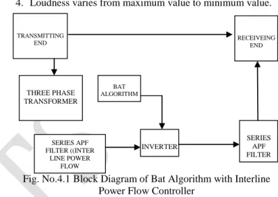
4. Loudness varies from maximum value to minimum value.
Fig. No.4.1 Block Diagram of Bat Algorithm with Interline Power Flow Controller
4.1 Existing
Two receiving end and getting two variations and if effect by sag and swell problem also in existing it included the two series converter to get accuracy in transmission to mitigate transmission loss but it effected by some harmonics problems. Here it included the two receiving end and two series converter to get better accuracy and to eliminate transmission loss.
4.2 Proposed
In this proposed method is tested verified and included the active power filters both shunt and series to mitigate harmonics, that allows the electrical devices to function is their planned without loss of performance. The effect of ramp-rate limits on generations and the effect of dynamic loads on generation and transmission losses are also analyzed. In proposed we delivering at single receiving end with all the performance and characteristics according to load and we shows the THD in graph. Then In this system we reduce the complexity and algorithm formatted to simulink model.
CHAPTER 5
OPTIMAL LOCATION OF IPFC
In general, to obtain maximum benefit from IPFC, it is necessary to identify an optimal location to install this device in a given system. Here, IPFC is a multi line FACTS controllers, it requires two different transmission lines with a common bus to install the same. So, the conventional optimal location identification methodologies are not suitable to
TRANSMITTING END
INVERTER
SERIES APF FILTER ((INTER
LINE POWER FLOW ONTROLLER)
THREE PHASE TRANSFORMER
BAT ALGORITHM
RECEIVEING END
78 identify an optimal location. Mostly, this device is used to control the power flow in the transmission lines by varying the compensation using voltage source converter. Because of this, the power flow in some of transmission lines gets increased and in some of the transmission lines gets decreased. In this paper, line stability index based location is identified and the complete details are given below:
5.1. Line stability Index (LSI) Location
From the literature, the severity index (Xinghao et al., 2009) is calculated based on the active/apparent power flows in transmission lines. Even though, severity index and ranking methods are popular and have certain disadvantages. It cannot consider the stability of a transmission line into consideration. Hence in this paper, a new procedure is developed to identify an optimal location based line stability index (LSI). This index directly represents the stability of the system in terms of line loadings. The minimum and maximum limits for this index are ‗0' (no-load condition) and ‗1' (system collapse condition). This LSI value for a line connected between buses i and j can be represented as (Lof et al., 1993).
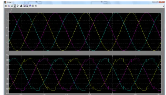
Fig. No.5.1 Without Unified Power Qualifying Control Input
Fig. No.5.2 Without Unified Power Qualifying Control Output
Fig. No.5.3 Regulating Each Phase with BAT
Fig. No.5.4 Before Unified Power Qualifying Control algorithm
Fig. No. 5.5 Feedback of Interline Power Flow
Fig.No.5.6 Interline Power Flow with Unified Power Qualifying Control
CHAPTER 6 CONCLUSION
79
REFERENCES
[1] X. S. Yang, ―Harmony Search as a Metaheuristic Algorithm,‖ Music-Inspired Harmony Search Algorithm: Theory and Applications, Studies in Computational Intelligence, vol. 191, pp.1-14, 2009.
[2] X. S Yang, Nature-inspired Metaheuristic Algorithms, 2nd Edition, Luniver Press, 2008.
[3] W. Gao and S. Liu, ―A Modified Artificial Bee Colony Algorithm,‖ Computers and Operations Research, vol. 39, pp. 687-697, 2012.
[4] X. S. Yang, ―A New Metaheuristic Bat-Inspired Algorithm,‖ in Nature Inspired Cooperative Strategies for Optimization (NISCO 2010), J. R. Gonzalez et al., Eds., Springer Press, 2010, vol. 284, pp. 65-74.
[5] X.S. Yang, ―Bat algorithm for multi-objective optimization,‖ International Journal of Bio-Inspired Computation, vol. 3, no. 5, pp.267-274, 2011.
[6] R. Nakamura, L. Pereira, K. Costa, D. Rodrigues, J.Papa, and X.S.Yang, ―BBA:A Binary Bat Algorithm for Feature Selection,‖ in Proc. 25th SIBGRAPI Conference on Graphics, Patterns and Images (SIBGRAPI), Aug. 22-25, 2012, pp.291-297.
[7] G.Komarasamy and A. Wahi, ―An Optimized K-Means Clustering Technique using Bat Algorithm,‖ European Journal of Scientific
[8] G. Wang and L. Guo, ―A Novel Hybrid Bat Algorithm with Harmony Search for Global Numerical Optimization,‖ Journal of Applied Mathematics, vol. 2013, pp. 21, 2013.
[9] J. Kennedy and R. Eberhart, ―Particle swarm optimization,‖ in Proc. IEEE Int. Conf. Neural Network, Perth, Australia, 1995, pp.1942-1948.
[10] Y.H.Shi and R.C.Eberhart, ―A modified particle swarm optimizer,‖ Evolutionary Computation Proceedings, IEEE World Congress on Computational Intelligence, The 1998 IEEE International Conference on, Anchorage Alaska, 1998, pp.69-73.
ACKNOWLEDGEMENT
I express my sincere and heart-felt gratitude to the
management of RVS COLLEGE OF ENGINEERING
AND TECHNOLOGY, for providing me with the entire necessary infrastructure and other facilities to successfully complete this project.
BIOGRAPHY
D.JAYANTHI received her B.E
(Electrical and Electronics Engineering)
degree from Anna University,
Coimbatore, India in 2014 and currently pursuing her M.E (Power System and Drives) degree in RVS College of Engineering and Technology. Her area of interest is Electrical machines and drives.
Prof. K. Thangarajan M.E., (Ph.D)., He is currently working as Associate professor, Department of Electrical and Electronics Engineering in RVS College of
Engineering and Technology,