CFD Analysis of a Rocket Nozzle withFour Inlets at Mach 2.1.
Parasa Lakshmana Kumar1, G.Sreenivas21PG Scholar, Pydah College of Engineering, Kakinada, AP, India. 2Associate Professor, Pydah College of Engineering, Kakinada, AP, India.
ABSTRACT
In this work CFD investigation of weight and temperature for a rocket spout with four channels at Mach 2.1 is examined with the assistance of familiar programming. at the point when the fuel and air enter in the ignition chamber as indicated by the x and y plot, it is smoldering because of high speed and temperature and afterward temperature increments quickly in burning chamber and joined a portion of the spout and after that temperature diminishes in the way out some portion of the spout. it is deduced in this paper Four gulf rocket spout is having preferred execution over single channel and two delta as seen from the past exploration work done. Keywords:CFD1,examined2, ignition3,
temperature4. INTRODUCTION
A rocket engine is a type of jet engine that uses only stored rocket propellant mass for forming its high speed propulsive jet. Rocket engines are reaction engines, obtaining thrust in accordance with Newton's third law. Most rocket engines are internal combustion engines, although non-combusting forms also exist. Vehicles propelled by rocket engines are commonly called rockets. Since they need no external material to form their jet, rocket engines can perform in a vacuumand thus can be used to propel spacecraft and ballistic missiles.Rocket engines as a group have the highest thrust, are by far the lightest, but are the least propellant efficient (have the lowest specific impulse) of all types of jet engines. The ideal exhaust is hydrogen, the lightest of all gases, but chemical rockets produce a mix of heavier
(due to greater propulsive efficiency and Oberth effect). Since they do not benefit from, or use, air, they are well suited for uses in space and the high atmosphere.
1.1 Principle of Operation:
Rocket engines produce thrust by the expulsion of exhaust which has been accelerated to a high-speed.
The exhaust must be a fluid, usually a gas created by high pressure (10-200 bar) combustion of solid or liquid propellants, consisting of fuel and oxidiser components, within a combustion chamber. (An exception is water rockets, which use water pressurised by compressed air, carbon dioxide, nitrogen, or manual pumping.)The exhaust is then passed through a supersonic propelling nozzle which uses heat energy of the gas to accelerate the exhaust to very high speed, and the reaction to this pushes the engine in the opposite direction.In rocket engines, high temperatures and pressures are highly desirable for good performance as this permits a longer nozzle to be fitted to the engine, which gives higher exhaust speeds, as well as giving better thermodynamic efficiency.
1.2. Introducing propellant into a combustion chamber:
high-Fig:1.A solid rocket motor.
Solid rocket propellants are prepared as a mixture of fuel and oxidising components called 'grain' and the propellant storage casing effectively becomes the combustion chamber. Liquid-fuelled rockets typically pump separate fuel and oxidiser components into the combustion chamber, where they mix and burn. Hybrid rocket engines use a combination of solid and liquid or gaseous propellants. Both liquid and hybrid rockets use injectors to introduce the propellant into the chamber. These are often an array of simple jets -holes through which the propellant escapes under pressure; but sometimes may be more complex spray nozzles. When two or more propellants are injected, the jets usually deliberately cause the propellants to collide as this breaks up the flow into smaller droplets that burn more easily.
Fig: 2.Rocket
Fig:3.This section through an ED nozzle clearly shows the pintle. In this example the outer wall appears similar to the internal contour of a bell nozzle.
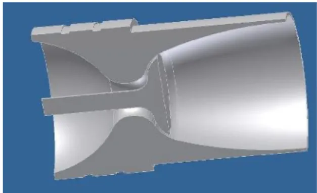
Fig: 4.half section view of rocket
The basic concept of any engine bell is to
efficiently expand the flow of exhaust gases from
the rocket engine into one direction. The exhaust,
a high-temperature mix of gases, has an
effectively random momentum distribution, and
small part of the flow will be moving in the
correct direction to contribute to forward thrust.
Comparison between the design of a bell-nozzle
rocket (left) and an aero spike rocket (right)
Instead of firing the exhaust out of a small hole in
the middle of a bell, an aero spike engine avoids
this random distribution by firing along the
outside edge of a wedge-shaped protrusion, the
"spike". The spike forms one side of a virtual
bell, with the other side being formed by the
outside air—thus the "aero spike".
The idea behind the aero spike design is that at
low altitude the ambient pressure compresses the
wake against the nozzle. The recirculation in the
base zone of the wedge can then raise the
pressure there to near ambient. Since the pressure
on top of the engine is ambient, this means that
the base gives no overall thrust (but it also means
that this part of the nozzle doesn't lose thrust by
forming a partial vacuum, thus the base part of
the nozzle can be ignored at low altitude).
RESULTS AND DISCUSSION
This CFD numerical experiment allows us to
parameter being equal in a fashion impossible to obtain in an actual levorotatory experiment. A numerical study has been conducted to understand the gas flow in a nozzles using 2D continuum axi symmetric model, which solves the properties of combustion by the control volume method. The numerical model was validated with exiting experimental data employing slip and no-slip boundary condition at the wall. The numerical results showed good agreement with experimental data on exit.
A. Rocket Nozzle with Combustion Chamber
1) Total Pressure
Figure-6 Total Pressure
1) TotalTemperature
The average temperature in combustion chamberis 2.54e+03, and maximum temperature is 3.67e+03, thetotal temperature decrease in the divergent part of thenozzle compared the combustion chamber and convergent partof the nozzle. When the fuel and air is enter in thecombustion
chamberaccordingtothexandyplot,itsburnduetohi gh velocity and temperature and then temperatureincrease
rapidlyincombustionchamberandconvergentpart ofthe nozzle and after that temperature decrease in the exit partof the nozzle. A maximum of 3.67e+03 is attained andbeyond which the temperature steadilydecreases.
Figure–7 TotalTemperatures
2) Turbulence Intensity
Figure- 7 Turbulence Intensity
1) Mass fraction ofC5H12
The maximum mass fraction of pentane is 1.00e-01 atthe fuel inlet is attained beyond which the mass fractionsteadily decrease,neartothewallmassfractionofpentaneis zero. When the chemical reaction occurs, the bondwithin molecules of the reactance is broken, and electronsrearrange to form product. in combustion reaction rapid oxidationof combustible element of the fuel results in energy releaseas combustion product are formed .When the fuel enter inthe combustionchamberisone.whileaswellasfuelent erin combustion chamber it cover higher value
1and after thatit
goesondecreaseinstraightthrownozzle,anditisle ssinthe part of the nozzle, near to the wall of
combustion chamberis
zero.Whentheusingfourjetforsameamountofair andfuel the value increase anddecreases.
Figure-7 Mass fractionofC5H12
2) Mass Fraction ofO2
For the same value of air and fuel if increase the fuelinlettheamountofairisdecreasecomparedtofuelamount .When the air is enter in the combustion chamber and burnedwith fuel,thenmassfractionhashigh01inthe combustion chamber and minimum value2.10e-02,andgoes on decreasing in part of the nozzle, while
near to thenozzle
wallmassfractionofoxygenhaszero.Duetothestreamline
increase in combustion chamber while it enters inthe divergent part of thenozzle.
Figure-8 Mass fraction ofO2
3) Mass fraction ofCo2
For the same value of air and fuel if increase the fuelinlettheamountofairisdecreasecomparedtofuelamount .When the air is enter in the combustion chamber and burnedwith fuel,thenmassfractionhashighvalue1.69e-01inthe combustion chamber and minimum
value.0791,and goeson
decreasinginpartofthenozzle,whileneartothenozzlewall mass fraction co2 has zero. Due to the stream line
flowmass
fractionofco2flowstraightinthenozzle.Accordingtoxand y
Figure-9 Mass fraction ofCo2
4) Mass fraction ofH2o
In combustion reaction rapid oxidation ofcombustible element of the fuel results in energy release ascombustion products formed. The three major combustible chemical element sinmost common fuel are carbon ,hydrogenand sulphur ,combustion is complete when all the carbonpresent
inthefuelisburned,allhydrogenburnedintowater,a nd other combustible element are fully oxidized. Herethe carbon dioxide is has the higher vale 8.30-02 andminimum value is zero. In the combustion chamber Carbon dioxideis zero means fuel is completely burned. Carbon dioxideis maximum at the exit part of thenozzle.
Figure-8 Mass fraction ofH2o
5) Mass fraction ofN2
Mass fraction near to the combustion chamber wallhas
highervalueis0.79,andaveragevalveis0.474andminimum valueneartothefuelinlet,whileaslongasaircoverthe distance in the combustion chamber the value goeson decrease.
Figure-10 Specific Heat
CONCLUSION
chamber and after that pressuregoes on decrease in the convergent portion and at the throattotal pressure is cover the negative value, due to supersonic nozzle total pressure in the convergent part is lessand velocity increase. The average temperature incombustion chamberis2.54e+03,andmaximumtemperatureis 3.67e+03, hetotal temperature decreaseinthe divergentpartofthe nozzle compared the combustion chamber andconvergent partofthenozzle.Whenthefuelandairisenterinthe combustion chamber according to the x and y plot, itsburn due to high velocity and temperature and thentemperature increase rapidly in combustion chamber and convergentpart of the nozzle and after that temperature decrease in theexitpart of the nozzle. A maximum of 3.67e+03 is attainedand beyond which the temperature steadily decreases.The
maximummassfractionofpentaneis1.00e-01atthefuel inlet is attained beyond which the mass fractionsteadily decrease, near to the wall mass fraction of pentane is zero.
REFERENCES
Boris M. Kiforenko, Zoya V. Pasechnik and
IgorYu. Vasil’ev,“Comparison of the rocket
engines efficiency in the case of low thrust orbit-to-orbit transfers”,ActaAstronauticaVol
60, 2007,pp- 801-809.
[2] ZhigangFeng and QiWang “Research on health evaluation system of liquid-propellant rocket engine ground-testing bed based on fuzzytheory”, ActaAstronauticaVol 61,2007,
pp-840-853.
[3] VadimZakirov and Vladimir Pavshook;
“Russian Nuclear Rocket Engine Design for
Mars Exploration”, Tsinghua Science And
Technology.,Vol 12, 2007, pp-256-260.
[4] Johannes Lux , Dmitry Suslov and Oskar
Haidn, “porous liquid propellant rocket
engine injectors”, Aerospace Science and Technology, Vol 12, 2007, pp-469-477.
cooled nozzle extensions of liquid rocket
engines”,Acta Astronautica, Vol 64, 22-27.
[6] G. Lacaze, B. Cuenot, T. Poinsot and M.
Oschwald, “Large eddy simulation of laser ignition and compressible reacting flow in a rocket-like configuration”, Combustion and Flame, Vol 156,
2007,PP-1166-1180. [7]
ValeriyI.Timoshenkoa,IgorS.Belotserkovetsa, Vjacheslav,P.Gusininb, “Problems of
providing completeness of the methane-containing block-jet combustion in a
rocket-ramjet engine’s combustion chamber”,
ActaAstronautica, Vol 65, 2009,
pp-231-1237.
[8] M. Masquelet, S. Menona, Y. Jinband R.
Friedrich, “Simulation of unsteady
combustion in a LOX-GH2 fueled rocket engine”, Aerospace Science and Technology
Vol 13, 2009, pp-466-474.
[9] David R. Greatrix, Regression rate estimation for standard-flow hybrid rocket engines, Aerospace Science and Technology 13, 358-363, (2009).
[10] K.M.Pandey and S.K.Yadav, “CFD
Analysis of a Rocket Nozzle with Two Inlets
at Mach 2.1”, Journal of Environmental
Research and Development, Vol 5, No 2,