New Hybrid Active Filter Topology With Variable Conductance For Reduced
Harmonic Distortion
P Satya Sri1, P Govinda Raju2
M.Tech Student, Department of EEE, PCET,Anathavaram.1 Asst. Professor, Department of EEE, PCET,Anathavaram.2
Abstract-Unintentional series and/or parallel resonances, due to the tuned passive filter and the line inductance, may result in severe harmonic distortion in the industrial power system. This project presents a hybrid active filter to suppress harmonic resonance and to reduce harmonic distortion. The proposed hybrid filter is operated as variable harmonic conductance according to the voltage total harmonic distortion; therefore, harmonic distortion can be reduced to an acceptable level in response to load change or parameter variation of the power system by using fuzzy controller. Since the hybrid filter is composed of a seventh-tuned passive filter and an active filter in series connection, both dc voltage and kVA rating of the active filter are dramatically decreased compared with the pure shunt active filter. In real application, this feature is very attractive since the active power filter with fully power electronics is very expensive. A reasonable tradeoff between filtering performances and cost is to use the hybrid active filter. Total harmonic distortion is reduced by using fuzzy controller Further more, this project discusses filtering performances on line impedance, line resistance, voltage unbalance, and capacitive filters. The results verified through MATLAB/SIMULINK environment.
Index Terms—Harmonic resonance, hybrid active filter,
industrial power system.
INTRODUCTION
HARMONIC pollution is becoming increasingly serious due to extensive use of nonlinear loads, such as adjustable speed drives, uninterruptible power supply systems, battery charging system, etc. This equipment usually uses diode or thyristor rectifiers to realize power conversion because of lower component cost and less control complexity. However, the rectifiers will contribute a large amount of harmonic current flowing into the power system, and the resulting harmonic distortion may give rise to malfunction of sensitive equipment or interfering with communication systems in
the vicinity of the harmonic sources. Normally, tuned passive filters are deployed at the secondary side of the distribution transformer to provide low impedance for dominant harmonic current and correct power factor for inductive loads [1], [2]. However, due to parameter variations of passive filters, unintentional series and/or parallel resonances may occur between the passive filter and line inductance. The functionality of the passive filter may deteriorate, and excessive harmonic amplification may result [3], [4].
Thus, extra calibrating work must be consumed to maintain the filtering capability. Various active filtering approaches have been presented to address the harmonic issues in the power system [5]–[7]. The active filter intended for compensating harmonic current of nonlinear loads is the most popular one, but i t may not be effective f or suppressing harmonic r resonances [8]. Bhattacharya and Divan proposed a hybrid series active filter t o isolate harmonics between the power system and the harmonic source [9]. A s o-called “active i inductance” hybrid filter was presented to improve the performance of the passive filter. Fujita et al. proposed a hybrid shunt active filter with filter-current detecting method to suppress the fifth harmonic resonance between the power system and a capacitor bank.
A hybrid filter in series with a capacitor bank by a coupling transformer was proposed to suppress the harmonic resonance and to compensate harmonic current. However, this method needs extra matching transformers or tuned passive filters to guarantee filtering functionality. Recently, a transformer less hybrid active filter was presented to compensate harmonic current and/or fundamental reactive current . Design consideration of the hybrid filter for current compensation has been extensively studied.
New Hybrid Active Filter Topology With Variable Conductance For Reduced
Harmonic Distortion
P Satya Sri1, P Govinda Raju2
M.Tech Student, Department of EEE, PCET,Anathavaram.1 Asst. Professor, Department of EEE, PCET,Anathavaram.2
Abstract-Unintentional series and/or parallel resonances, due to the tuned passive filter and the line inductance, may result in severe harmonic distortion in the industrial power system. This project presents a hybrid active filter to suppress harmonic resonance and to reduce harmonic distortion. The proposed hybrid filter is operated as variable harmonic conductance according to the voltage total harmonic distortion; therefore, harmonic distortion can be reduced to an acceptable level in response to load change or parameter variation of the power system by using fuzzy controller. Since the hybrid filter is composed of a seventh-tuned passive filter and an active filter in series connection, both dc voltage and kVA rating of the active filter are dramatically decreased compared with the pure shunt active filter. In real application, this feature is very attractive since the active power filter with fully power electronics is very expensive. A reasonable tradeoff between filtering performances and cost is to use the hybrid active filter. Total harmonic distortion is reduced by using fuzzy controller Further more, this project discusses filtering performances on line impedance, line resistance, voltage unbalance, and capacitive filters. The results verified through MATLAB/SIMULINK environment.
Index Terms—Harmonic resonance, hybrid active filter,
industrial power system.
INTRODUCTION
HARMONIC pollution is becoming increasingly serious due to extensive use of nonlinear loads, such as adjustable speed drives, uninterruptible power supply systems, battery charging system, etc. This equipment usually uses diode or thyristor rectifiers to realize power conversion because of lower component cost and less control complexity. However, the rectifiers will contribute a large amount of harmonic current flowing into the power system, and the resulting harmonic distortion may give rise to malfunction of sensitive equipment or interfering with communication systems in
the vicinity of the harmonic sources. Normally, tuned passive filters are deployed at the secondary side of the distribution transformer to provide low impedance for dominant harmonic current and correct power factor for inductive loads [1], [2]. However, due to parameter variations of passive filters, unintentional series and/or parallel resonances may occur between the passive filter and line inductance. The functionality of the passive filter may deteriorate, and excessive harmonic amplification may result [3], [4].
Thus, extra calibrating work must be consumed to maintain the filtering capability. Various active filtering approaches have been presented to address the harmonic issues in the power system [5]–[7]. The active filter intended for compensating harmonic current of nonlinear loads is the most popular one, but i t may not be effective f or suppressing harmonic r resonances [8]. Bhattacharya and Divan proposed a hybrid series active filter t o isolate harmonics between the power system and the harmonic source [9]. A s o-called “active i inductance” hybrid filter was presented to improve the performance of the passive filter. Fujita et al. proposed a hybrid shunt active filter with filter-current detecting method to suppress the fifth harmonic resonance between the power system and a capacitor bank.
BLOCK DIAGRAM:
Fig. 1. Proposed HAFU in the industrial power system and its associated control. (a) Circuit diagram of the
HAFU. (b) Control block diagram of the HAFU
II. OPERATION P RINCIPLE
Fig. 1(a) shows a simplified circuit diagram considered in this project, where Ls represented the line inductance plus the leakage inductance of the transformer. The hybrid active filter unit (HAFU) is constructed by a seventh-tuned passive filter and a three-phase voltage source inverter in series connection. The passive filter Lf − Cfis intended for compensating harmonic current and reactive power. The inverter is designed to suppress
harmonic resonances and improve the filtering performances of the passive filter. Fig. 1(b) shows the overall control block diagram of the HAFU, including harmonic loop, fundamental loop, current regulator, and conductance control. A detailed principle will be presented as follows.
A. Harmonic Loop
To suppress harmonic resonances, the HAFU is proposed to operate as variable conductance at harmonic frequencies as follows:
i∗ = G∗. e (1)
where i∗ h represents the harmonic current command. The conductance command G∗ is a variable gain to provide damping for all harmonic frequencies. Harmonic voltage component eh is obtained by using the so-called SRF transformation [9], where a phase-locked loop (PLL) is realized to determine the fundamental frequency of the power system . In the SRF, the fundamental component becomes a dc value, and other harmonic components are still ac values. Therefore, harmonic voltage component eeqd,h can be extracted from eeqd by using high pass filters.
After transferring back to a three-phase system, the harmonic current command i∗h is obtained by multiplying eh and the conductance command G∗, as shown in (1).
B. Fundamental Loop
v > 2√2 ∑ ω + jω L . I (2) C. Current Regulator
The current command i∗ is consisted of i∗ h and i∗f. Based on the current command i∗ and the measured current i, the voltage command v∗ can be derived by using a proportional controller as follows:
v∗= K . (i∗− i) (3)
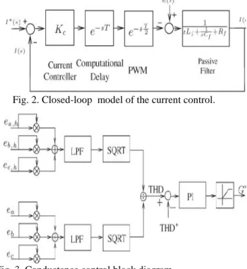
where Kc is a proportional gain. According to the voltage command v∗, space-vector pulse width modulation (PWM) is employed to synthesize the required output voltage of the inverter. Fig. 2 shows the model of the current control. The computational delay of digital signal processing is equal to one sampling delay T, and PWM delay approximates to half sampling delay T/2. Hence, the proportional gain Kc can be simply evaluated from both open-loop and closed-loop gains for suitable stability margin and current tracking capability.
Fig. 2. Closed-loop model of the current control.
Fig. 3. Conductance control block diagram.
The frequency-domain analysis of current control will be given in Section IV.
D. Conductance Control
Fig. 3 shows the proposed conductance control. The harmonic conductance command G∗ is determined according to the voltage THD at the HAFU installation point. The voltage THD is approximately calculated by the control shown in Fig. 3. Here, two low-pass filters
(LPFs) with cutoff frequency fLP = 20 Hz are realized to filter out ripple components [29], [30]. The error between the allowable THD∗and the measured THD is then fed into a PI controller to obtain the harmonic conductance command G∗. The allowable distortion could be referred to the harmonic limit in IEEE std. 519-1992 [31].Note that PI parameters need to be tuned for required response and stability. For example, the proportional gain can be tuned for transient behavior, and the integral gain is responsible for suppressing the steady-state error. The bandwidth should be lower than one-tenth of the cutoff frequency of the current loop to assure stable operation.
III. ANALYSIS OF FILTERING PERFORMANCE The filtering performance of the HAFU has been addressed in [25] by developing equivalent circuit models, in which both harmonic impedance and harmonic amplification are considered. The frequency characteristic of the passive filter is changed by the proposed harmonic conductance to avoid unintentional resonances. Here, we will concentrate on the damping performance with variation of line impedance Ls, line resistance Rs, and THD∗. Voltage unbalance and filter capacitors in the power system are also considered.
IV.FUZZY LOGIC CONTROL
FLC determined by the set of linguistic rules. The mathematical modeling is not required in fuzzy controller due to the conversion of numerical variable into linguistic variables. FLC consists of three part: a. Fuzzification, b. Interference engine, c. Defuzzification. The fuzzy controller is characterized as; For each input and output there are seven fuzzy sets. For simplicity a membership functions is Triangular. Fuzzification is using continuous universe of discourse. Implication is using Mamdani's "min" operator. Defuzzification is using the "height" method.
FIG4:SIMULINK BLOCK DIAGRAM
FIG5:SIMULINK CONTROL DIAGRAM
6a
6b
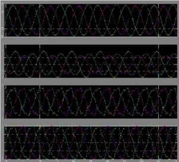
Fig. 6. Line voltage e, source current is, load current iL, and filter current i in the case of NL1 initiated. X-axis: 5 ms/div. (a) HAFU is off. (b) HAFU is on.
Fig. 7. Line voltage e, source current is, load current iL, and filter
current i in the case of NL2 initiated. X-axis: 5 ms/div. .
8a
8b
X-axis: 100 ms/div; Y -axis: vdc(V), G∗(1.21 p.u./div), and THD (1.25%/div). (b) Current waveforms.
Fig. 9. HAFU is off for single-phase nonlinear load.
Fig. 10. HAFU is on for single-phase nonlinear load.
V. CONCLUSION
This project presents hybrid active filter to uppers harmonic resonances in industrial power systems. The proposed hybrid filter is composed of a seventh harmonic-tuned passive filter and an active filter in series connection at the secondary side of the distribution
transformer. With the active filter part operating as variable harmonic conductance, the filtering performances of the passive filter can be significantly improved. Accordingly, the harmonic resonances can be avoided, and the harmonic distortion can be maintained inside an acceptable level in case of load changes and variations of line impedance of the power system. Simulation results verify the effectiveness of the proposed method. Extended discussions are s summarized as follows.
Large line inductance and large nonlinear load may result in severe voltage distortion. The conductance is increased to maintain distortion to an acceptable level.
Line resistance may help reduce voltage distortion. Total harmonic distortion is reduced by using fuzzy controller.
For low line impedance, THD∗should be reduced to enhance filtering performances. In this situation, measuring voltage distortion becomes a challenging issue.
High-frequency resonances resulting from capacitive filters is possible t o be suppressed by the proposed method.
In case of unbalanced voltage, a band-rejected filter is needed to filter out second-order harmonics if the SRF is realized to extract voltage harmonics.
REFERENCES
[1] Tzung-Lin Lee, Member, IEEE, Yen-Ching Wang, Student Member, “Hybrid Active Filter With Variable Conductance for Harmonic Resonance Suppression in Industrial Power Systems” IEEE, Jian-Cheng Li, and Josep M. Guerrero, Senior Member, IEEE
[2] R . H. Simpson, “Misapplication o f power capacitors in distribute tion systems with nonlinear loads-three case histories,”I E E E Tra n s . I n d . A p p l ., vol. 41, no. 1, pp. 134–143, Jan./Feb.2005.
[4] T. Di ionize and V. Lorch, “Voltage distortion on an electrical distribution system,” IEEE In d . A p p l . M ag., vol. 16, no. 2, pp. 48–55, Mar./Apr. 2010.
[3] E. J. Currence, J. E. Plizga, and H. N. Nelson, “Harmonic resonance at a medium-sized industrial plant,”IEEE Tra n s . I n d . A p p l ., vol. 31, no. 4, pp. 682–690, Jul/Aug. 1995.
[6] H. Akagi, “Active harmonic filters,”Proc. IEEE, vol. 93, no. 12, pp. 2128–2141, Dec. 2005.
[7] A. Bhattacharya, C. Chakraborty, and S. Bhattacharya, “Shunt compensation,” IEEE Ind. Electron. Mag., vol. 3, no. 3, pp. 38–49, Sep. 2009.
[8] F. Z. Peng, “Application issues of active power filters,”IEEE Ind. Appl. Mag., vol. 4, no. 5, pp. 21–30, Sep./Oct. 2001
.