Testing FM Systems on the
FP35 Hearing Aid Analyzer
Introduction
This workbook describes how to test FM systems with the FP35 Hearing Aid Analyzer using coupler measurements. An FM sys-tem consists of two main parts: a transmitter and a receiver. The transmitter microphone can come in many different sizes and shapes, and it can be nondirectional or directional. The receiver can be a button earphone, or it can be attached to a BTE hearing aid either internally, via a boot receiver, via a silhouette coil, or via a neck loop. No matter the combination, all FM systems can be tested. These test procedures should be performed on an FM system at least once a year. For children under the age of 5, these procedures should be performed every six months.
Testing FM Systems on the
FP35 Hearing Aid Analyzer
As with most hearing aids, both the gain and the maximum output (OSPL) of an FM system should be adjusted to meet the listener’s auditory requirements.
There are several issues to consider when comparing the hearing aid and FM performance.
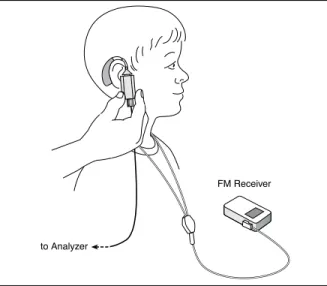
With FM systems, the pickup microphone is normally •
worn at the chest, 6-8 inches (15-20 cm) under the mouth of the talker, whereas with hearing aids, the pickup mi-crophone is worn by the listener, typically at a minimum of 3 ft. (1 m) from the talker. This difference affects both the level and the frequency content of typical input sig-nals. With FM systems, typical speech input levels range from 75 to 85 dB SPL, as compared with 60 to 70 dB SPL for hearing aids. With the chest-worn location of the pickup microphone, the high frequencies are relatively
lower in level (about 5 dB at 5 kHz) and the low frequen-cies are relatively higher in level (about 5 dB at 500 Hz) as compared with directly in front of the talker’s mouth. The increased “vocal effort” by teachers in a classroom •
situation may create further changes to the speech spec-trum at the input to an FM system, as compared with the speech spectrum at the input of a hearing aid (Cornelisse et al., 1991).
FM systems often have an automatic gain control (AGC) •
or other nonlinear characteristic that could interact with that of the hearing aid being used to deliver the FM signal—if such a hearing aid is being used in this fashion. The frequency response of an FM system is often not as •
adjustable as that of a hearing aid, limiting the range of electroacoustic modifications available.
It is recommended that the FM system provide a +10 •
dB advantage over the hearing aid microphone for best audibility.
The procedures recommended in this workbook are based upon the FM Offset Procedure, sometimes called the Phonak FM Offset Procedure or POP, which is available for download from www. phonak.com. Using this procedure, the output from the FM sys-tem is matched to the output from the hearing aid microphone. It is assumed that the actual FM output will have a +10 dB ad-vantage over the hearing aid microphone when the adjustments made in this procedure are followed since the typical input to the FM system will be higher (75-85 dB SPL) than the typical input to the hearing aid microphone (60-70 dB SPL).
Basic FM Offset Procedure
This section describes the basic FM Offset Procedure. Step-by-step instructions on how to implement this procedure on the FP35 Hearing Aid Analyzer are described later in this workbook.
Program the hearing aid appropriately for the hearing loss 1.
of the patient.
Turn OFF any automatic feedback control and/or noise 2.
reduction on the hearing aid, if possible. Attach the FM receiver to the hearing aid. 3.
Program the FM receiver for a +10 dB FM advantage. 4.
Set the FM system to the FM+Hearing Aid (or FM + Mic) 5.
Place the hearing aid in the test box with the FM micro-6.
phone outside the text box on mute or in a quiet environ-ment.
Determine the RMS Out using this test setup with a 65 dB 7.
SPL broadband signal (HA-65).
Switch the positions of the hearing aid and the FM micro-8.
phone so that the FM microphone is inside the test box and the hearing aid is outside the test box (but still at-tached to the coupler).
Determine the RMS Out using this test setup with a 65 dB 9.
SPL broadband signal (FM-65).
Calculate the FM Offset = FM-65 – HA-65. If the differ-10.
ence is ±2 dB, adjust the output of the FM system. If the FM Offset is equal to or greater than +2 dB, then you will need to reduce the FM gain level in the receiver by the
offset value. If the FM Offset is equal to or less than -2 dB, then you will need to increase the FM internal gain set-ting by the offset value.
Repeat steps 6-10 until the FM Offset is within ±2 dB. 11.
Place the hearing aid in the test box with the FM micro-12.
phone outside the text box on mute or in a quiet environ-ment.
Perform a frequency response measurement using a pure-13.
tone sweep with a 90 dB SPL input. Make sure the re-sponse doesn’t exceed maximum output targets.
Switch the positions of the hearing aid and the FM mi-14.
crophone so that the FM microphone is inside the test box and the hearing aid is outside the test box (but still attached to the coupler). Make sure the response doesn’t exceed maximum output targets.
Attaching the FM Receiver to a Coupler
A variety of output devices can be used with FM systems. These include button earphones, behind-the-ear (BTE) units with an internal FM receiver, an external FM receiver boot, or options for coupling to the personal BTE hearing aid via direct audio inputs, silhouette coils, or neck loops. This section tells you how to ar-range the 2-cc coupler with each type of output device.
Foam Pad Foam Pad Foam Pad
to Analyzer to Analyzer to Analyzer
FM
Receiver ReceiverFM ReceiverFM
Figure 1A
Button Earphone
Figure 1C
Silhouette Coil
Figure 1B
Internal FM Receiver, External FM Boot Receiver
Button earphone (Figure 1A)
If necessary, remove the ear-level adapter from the HA-2 1.
coupler.
Snap on the button earphone to the HA-2 coupler. 2.
Place the coupler/hearing-aid assembly on a foam pad 3.
outside the text box.
BTE microphone/receiver or BTE aid with internal FM receiver,
ex-ternal FM boot receiver, or direct audio input (Figure 1B)
Attach the ear-level adapter to the HA-2 coupler, if 1.
necessary.
Attach the BTE hearing aid to the HA-2 coupler. 2.
Set the switch on the position to receive the signal. 3.
Place the coupler/hearing-aid assembly on a foam pad 4.
outside the test box.
BTE aid with silhouette coil (Figure 1C)
Attach the ear-level adapter to the HA-2 coupler, if 1.
necessary.
Attach the BTE hearing aid to the HA-2 coupler. 2.
Place the coupler/hearing-aid assembly on a foam pad 3.
outside the test box on a nonmetallic surface during testing.
Choose a location free of stray magnetic fields (away from 4.
video monitors and other electrical devices).
Align the silhouette coil underneath the hearing aid, 5.
simulating the way it would be worn on the ear. Set the hearing aid for “T.”
BTE aid with neck loop (Figure 1D)
Within the range of the coupler microphone cable, choose 1.
a location to seat the listener that is free of stray magnetic fields (away from video monitors and other electrical devices).
Place the neck loop around the listener’s neck or around 2.
the neck of a person of similar size.
Attach the listener’s hearing aid to the HA-2 coupler and 3.
set it to the “T” position with a normal use setting of the volume control.
While holding the coupler in hand, place the hearing aid 4.
at the listener’s ear, as typically worn.
Take care not to move or touch the coupler microphone 5.
to Analyzer
FM Receiver
Occluding the Second Microphone
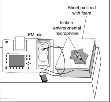
The FM Offset procedure described in this workbook performs sequential measurements of the hearing aid microphone and FM microphone. In most cases, the second microphone not being tested (that is, if the hearing aid is in the test box, the FM mi-crophone or vice versa) is still active although it won’t receive the test signal directly. Therefore, this test procedure must be performed in a quiet environment with low ambient noise. It is recommended to further isolate the second active microphone by placing it inside a spare sound chamber (if one is available) or even a shoebox lined with foam. This will help improve test accuracy.
Step-by-Step FM Offset Test Procedure
Press [F3] from the Opening Screen (with the Frye logo) to 1.
enter the Coupler Multicurve screen.
Level the sound chamber following the standard leveling 2.
procedure found in the Operator’s Manual.
Make sure the test graph is labeled “dB SPL” in the upper 3.
left corner of the screen. If it is labeled “dB GAIN,” press [MENU] and use the arrow keys to change the Display from Gain to SPL. Press [MENU] again to close the local menu. Program the hearing aid appropriately for the hearing loss 4.
of the patient.
Turn OFF any automatic feedback control and/or noise 5.
reduction on the hearing aid, if possible. Attach the FM receiver to the hearing aid. 6.
Program the FM receiver for a +10 dB FM advantage. 7.
Set the FM system to the FM+Hearing Aid (or FM + Mic) 8.
position.
Attach the hearing aid to the coupler, as described in the 9.
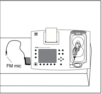
previous section and insert the coupler microphone. Place the hearing aid in the sound chamber with the hear-10.
ing aid microphone at the reference point of the chamber. Close and latch the lid. See Figure 2.
Place the FM microphone outside the sound chamber. If 11.
possible, mute the FM microphone. Otherwise, it is rec-ommended to place it within a sound occluding box. See Figure 2.
Use [F2] to select CRV 1. 12.
Use [F4] to select the DIG SPCH. 13.
Use the [
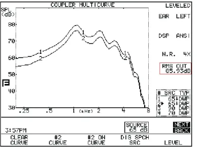
Press [START/STOP]. After the measurement has stabi-15.
lized, press [START/STOP] again the stop the test. Make note of the RMS OUT of the measurement. See Figure 3. Switch the positions of the hearing aid and the FM micro-16.
phone. That is, place the FM microphone at the reference point of the sound chamber and place the hearing aid outside the sound chamber while it is still attached to the coupler and analyzer microphone. Close and latch the lid of the sound chamber. See Figure 4.
Use [F2] to select CRV 2. 17.
Use [F4] to select the DIG SPCH. 18.
Use the [
19. , ] keys to set the Source to 65 dB SPL. Press [START/STOP]. After the measurement has stabi-20.
lized, press [START/STOP] again the stop the test. Make note of the RMS OUT of the measurement.
Subtract the RMS OUT of CRV 1 from the RMS OUT of 21.
CRV 2. This calculated number is the FM Offset.
If the difference less than ±2 dB, the FM receiver has •
been adjusted accurately and you may skip to the next section.
If the FM Offset is equal to or greater than +2 dB, •
then you will need to reduce the FM gain level in the receiver by the offset value.
If the FM Offset is equal to or less than -2 dB, then •
you will need to increase the FM internal gain setting by the offset value.
Adjust the gain of the FM receiver as determined in the 22.
previous step and repeat steps 10-21 until the FM Offset is less than ±2 dB.
FM mic
FONIXFP35 Hearing Aid Analyzer
OPERATE
Figure 3: The FM offset for this test is 85.9 - 89.5 = -3.6. The FM gain level needs to be increased by about 3 dB.
Step-by-Step Maximum Output Test
Procedure
This section describes make sure the FM system does not exceed the maximum output target. Obtaining the maximum target itself is outside the scope of this workbook.
Follow the steps in the previous section to adjust the FM 1.
Offset of the FM system. Use [F2] to select CRV 3. 2.
Use [F4] to select NORMAL. 3.
Use the [
4. , ] keys to set the Source to 90 dB SPL.
Place the hearing aid in the sound chamber, and place the 5.
FM microphone outside the sound chamber. Close and latch the lid. See Figure 2.
Press [START/STOP] to run the pure-tone sweep. The test 6.
will stop automatically.
Compare the test result to the maximum output target. 7.
Adjust the FM system if the measured response exceeds the target.
Switch the positions of the hearing aid and the FM mi-8.
crophone; place the FM microphone at the reference point inside the sound chamber and place the hearing aid outside the sound chamber. Close and latch the sound chamber lid. See Figure 3.
Use [F2] to select CRV 4. 9.
Use [F4] to select NORMAL. 10.
Use the [
Press [START/STOP] to run the pure-tone sweep. The test 12.
will stop automatically.
Compare the test result to the maximum output target. 13.
Adjust the FM system if the measured response exceeds the target.
If you have made any adjustments to the FM system, you 14.
may want to repeat the FM Offset test procedure to make sure that your changes didn’t affect the normal speech-level gain of the system.
Print the test results or use one of the FONIX software 15.
programs to save them to a computer database for future reference.
FONIX FP35 Hearing Aid Analyzer
Shoebox lined with foam Isolate
environmental microphone FM mic