Firewall Concepts and Configuration Guide
Edition 6
Manufacturing Part Number: none (PDF only) Version A.08.xx
2
Legal Notices
Warranty.Hewlett-Packard makes no warranty of any kind with regard to this document, including, but not limited to, the implied warranties of merchantability and fitness for a particular purpose. Hewlett-Packard shall not be held liable for errors contained herein or direct, indirect, special, incidental or consequential damages in connection with the furnishing, performance, or use of this material.
A copy of the specific warranty terms applicable to your Hewlett-Packard product can be obtained from your local Sales and Service Office.
Restricted Rights Legend.
Use, duplication or disclosure by the U.S. Government is subject to restrictions as set forth in subparagraph (c)(1)(ii) of the Rights in Technical Data and Computer Software clause in DFARS 252.227-7013. Hewlett-Packard Company
United States of America
Rights for non-DOD U.S. Government Departments and Agencies are as set forth in FAR 52.227-19(c)(1,2).
Copyright Notices.
©Copyright 2002-2006 Hewlett-Packard Development Company, L.P. No part of this document may be copied, reproduced, or translated to another language without the prior written consent of Hewlett-Packard Company. The information contained in this material is subject to change without notice.
Adobe is a trademark of Adobe Systems Incorporated.
HP-UX Release 10.20 and later and HP-UX Release 11.00 and later (in both 32 and 64-bit configurations) on all HP 9000 computers are Open Group UNIX 95 branded products.
Intel386, Intel80386, Intel486 , and Intel80486 are U.S. trademarks of Intel Corporation.
Intel Itanium Logo: Intel, Intel Inside and Itanium are trademarks or registered trademarks of Intel Corporation in the U.S. and other
countries and are used under license.
Java and all Java based trademarks and logos are trademarks or registered trademarks of Sun Microsystems, Inc. in the U.S. and other countries.
Microsoft is a U.S. registered trademark of Microsoft Corporation. MS-DOS is a U.S. registered trademark of Microsoft Corporation. Netscape and Netscape Navigator are U.S. trademarks of Netscape Communications Corporation.
OpenView is a registered U.S. trademark of Hewlett-Packard Company. Oracle is a registered U.S. trademark of Oracle Corporation, Redwood City, California.
OSF, OSF/1, OSF/Motif, Motif, and Open Software Foundation are trademarks of the Open Software Foundation in the U.S. and other countries.
Pentium is a U.S. registered trademark of Intel Corporation. SQL*Plus is a registered U.S. trademark of Oracle Corporation, Redwood City, California.
UNIX is a registered trademark of the Open Group.
1. Firewall Configuration in OVO
About this Chapter. . . 26
Naming Conventions . . . 26
OVO Communication Concepts . . . 27
HTTPS Agent and Management Server Communication . . . 27
DCE Agent and Management Server Communication. . . 29
OVO Heartbeat Monitoring . . . 31
Normal Heartbeat Monitoring . . . 31
RPC Only Heartbeat Polling (for Firewalls) . . . 31
Agent Sends Live Packets. . . 31
Communication Types . . . 32
HTTPS/TCP Communication . . . 33
DCE/UDP Communication . . . 33
DCE/TCP Communication . . . 33
Microsoft RPC Communication . . . 34
Sun RPC Communication . . . 34
NCS Communication. . . 34
Configuring OVO for Firewall Environments . . . 35
Special Configurations. . . 36
Motif User Interface . . . 36
OVO Java User Interface . . . 36
Configuring Ports for the Java GUI or Secure Java GUI . . . 36
Message Forwarding. . . 38
Communication Concepts in Message Forwarding . . . 39
Configuring Message Forwarding in Firewall Environments . . . 40
VP390/VP400 in Firewall Environments . . . 41
Network Address Translation . . . 43
Address Translation of Duplicate Identical IP Ranges . . . 44
Known Issues in NAT Environments . . . 45
FTP Does Not Work. . . 45
Contents
6
3. Configuring HTTPS Nodes
Specifying Client Port Ranges. . . 53
Management Server and Managed Node Port Settings. . . 54
Configuring a Firewall for HTTPS Nodes without a Proxy . . . 55
Configuring a Firewall for HTTPS Nodes with Proxies. . . 56
Configuring the OVO Management Server . . . 59
Configuring OVO Managed Nodes . . . 60
Systems with Multiple IP Addresses . . . 61
HTTPS Agents and Network Address Translation . . . 62
Address Translation of Outside Addresses . . . 62
Address Translation of Inside Addresses . . . 63
Address Translation of Inside and Outside Addresses. . . 64
IP Masquerading or Port Address Translation . . . 65
4. Configuring DCE Nodes
Management Server and Managed Node Port Settings. . . 69Configuring a Firewall for DCE Nodes . . . 72
Configuring the OVO Management Server . . . 73
Configuring OVO Managed Nodes . . . 75
Checking Communication Settings. . . 78
Verifying Communication Settings of the Management Server. . . 78
Verifying Communication Settings of Managed Nodes . . . 78
Checking the Endpoint Map. . . 78
Windows Managed Nodes . . . 80
Communicating with a Windows Managed Node Outside the Firewall . . . 80
Communication Types . . . 82
DCE/UDP Communication Type . . . 82
NCS Communication Type . . . 83
Sun RPC Communication Type . . . 83
MC/ServiceGuard in Firewall Environments . . . 85
Configuration Distribution . . . 87
Distributing the Configuration in an RPC Call . . . 87
Embedded Performance Component . . . 88
Configuring Ports for the Embedded Performance Component . . . 89
Configuring Reporter and/or Performance Manager . . . 91
Configuring Reporter/Performance Manager With HTTP Proxy. . . 93
Configuring Reporter/Performance Manager Without HTTP Proxy . . . 94
Changing the Default Port of the Local Location Broker . . . 95
Systems with Multiple IP Addresses. . . 95
Systems Installed with OpenView Operations for Windows . . . 96
Checkpoint Firewall-1 4.1 Integration . . . 97
Content Filtering . . . 97
Content Filtering for OVO . . . 98
Combining Content Filtering and Port Restrictions. . . 100
DCE Agents and Network Address Translation . . . 101
Address Translation of Outside Addresses . . . 101
Address Translation of Inside Addresses . . . 102
Configuring the Agent for the NAT Environment. . . 103
Address Translation of Inside and Outside Addresses. . . 104
Configuring the Agent for the NAT Environment. . . 105
Setting Up the Responsible Managers File . . . 105
IP Masquerading or Port Address Translation . . . 107
5. DCE RPC Communication without Using
Endpoint Mappers
About this Chapter. . . 110Concepts of Current OVO Communication. . . 111
DCE RPC Communication Concepts without using Endpoint Mappers . . . 112
Objectives for DCE Communication without Using Endpoint Mappers for OVO. . 113
Port Requirements for Remote Deployment . . . 114
Port Requirements for Manual Template and Instrumentation Deployment. . . 116
Communication Concepts. . . 118
Support Restrictions . . . 120
OVO Components Affected . . . 121
OVO Components Not Affected . . . 122
Contents
8
Example of a port configuration file . . . 126
RPC Server . . . 127
Example opcinfo or nodeinfo File Configuration . . . 128
Configuring Management Servers . . . 129
RPC Clients . . . 129
Commands Examples for Setting Port on an OVO Management Server. . . 130
RPC Servers. . . 130
Example Configuration . . . 132
Server Port Specification File. . . 133
File Syntax. . . 135
Example of an opcsvinfo File . . . 135
File Modification Test . . . 136
Internal Process Handling. . . 137
Variable Reference . . . 139
Examples . . . 141
Troubleshooting . . . 143
Diagnostics . . . 143
Tracing. . . 145
Testing . . . 149
A. Generic OVO Variables and Troubleshooting
Port Usage . . . 153General Notes on Port Usage . . . 153
RPC Servers . . . 153
RPC Clients. . . 153
TCP Socket Connections. . . 154
Port Usage on the Management Server. . . 155
Distribution Adapter (opcbbcdist) . . . 158
Installation/Upgrade/Patch Tool (ovdeploy). . . 158
Certificate Server (ovcs) . . . 158
Communication Utility (bbcutil) . . . 158
Display Manager (12000) . . . 158
Message Receiver (12001) . . . 158
Distribution Manager (12002) . . . 158
Communication Manager (12003) . . . 159
Forward Manager (12004-12005) . . . 159
Request Sender (12006-12040) . . . 159
TCP Socket Server (12051-12060) . . . 159
NT Virtual Terminal (12061) . . . 159
Troubleshooting Problems . . . 161
Defining the Size of the Port Range. . . 161
Monitoring Nodes Inside and Outside the Firewall . . . 162
Various Agent Messages. . . 162
Network Tuning for HP-UX 10.20 . . . 163
Network Tuning for HP-UX 11.x . . . 164
Network Tuning for Solaris . . . 166
Tracing of the Firewall . . . 167
Links . . . 168
B. OVO Variables and Troubleshooting for HTTPS Managed Nodes
Configuration Examples . . . 171Port Usage on Managed Nodes . . . 171
OVO Variables Used with HTTPS Agents and Firewalls . . . 173
SERVER_PORT . . . 173
SERVER_BIND_ADDR . . . 173
CLIENT_PORT . . . 174
CLIENT_BIND_ADDR. . . 174
PROXY. . . 174
HTTPS Managed Node Variables . . . 175
CLIENT_BIND_ADDR. . . 175
CLIENT_PORT . . . 175
PROXY. . . 176
SERVER_BIND_ADDR . . . 177
C. OVO Variables and Troubleshooting and DCE Managed Nodes
Configuration Examples . . . 181OVO Variables Used with DCE Agents and Firewalls. . . 182
OPC_AGENT_NAT. . . 183
Contents
10
CLIENT_BIND_ADDR(<app_name>) . . . 186
CLIENT_PORT(<app_name>) . . . 187
PROXY. . . 187
SERVER_BIND_ADDR(<app_name>) . . . 188
Communication Types . . . 188
DCE/UDP Communication Type . . . 188
NCS Communication Type. . . 189
Sun RPC Communication Type . . . 189
SERVER_PORT(<app_name>) . . . 190
Port Usage on Managed Nodes . . . 191
Control Agent (13001). . . 191
Distribution Agent (13011-13013) . . . 192
Message Agent (13004-13006) . . . 192
Communication Agent (13007). . . 192
NT Virtual Terminal (13008-13009) . . . 192
Embedded Performance Component (14000-14003) . . . 192
Troubleshooting Problems . . . 193
When All Assigned Ports Are in Use . . . 193
Error Messages for Unavailable Ports . . . 194
When the Server Does not Handle Port Ranges Automatically. . . 196
Error Messages for Server Port Handling . . . 196
Known Issues in NAT Environments . . . 198
Disabling Remote Actions Also Disables Operator-Initiated Actions . . . 198
Current Usage of the Port Range. . . 199
Communication Issues with NT Nodes . . . 200
The printing date and part number of the manual indicate the edition of the manual. The printing date will change when a new edition is printed. Minor changes may be made at reprint without changing the printing date. The part number of the manual will change when extensive changes are made.
Manual updates may be issued between editions to correct errors or document product changes. To ensure that you receive the updated or new editions, you should subscribe to the appropriate product support service. See your HP sales representative for details.
Table 1 Edition History
First Edition: May 1999
Second Edition: October 1999 Third Edition: August 2000 Third Edition (revised): July 2001 Fourth Edition: January 2002
Fifth Edition: July 2004
Fifth Edition (revised): September 2004 Sixth Edition: August 2006
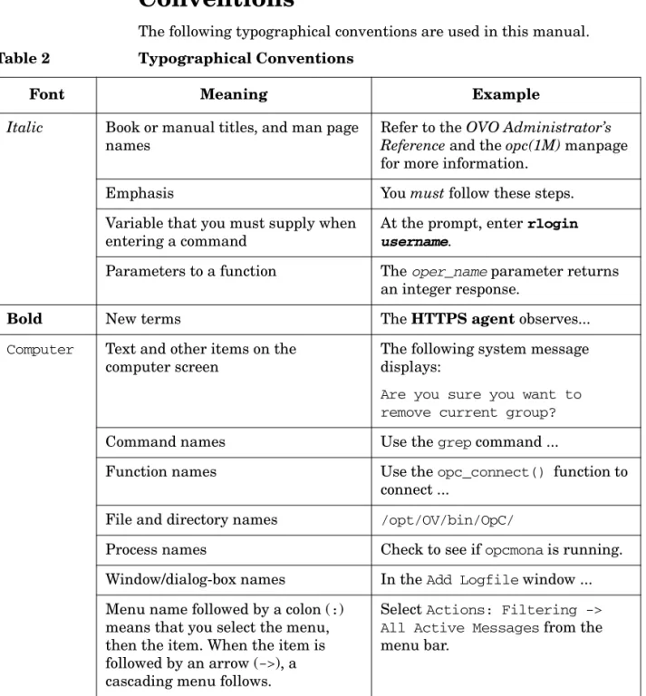
The following typographical conventions are used in this manual. Table 2 Typographical Conventions
Font Meaning Example
Italic Book or manual titles, and man page names
Refer to the OVO Administrator’s Reference and the opc(1M) manpage for more information.
Emphasis You must follow these steps. Variable that you must supply when
entering a command
At the prompt, enter rlogin
username.
Parameters to a function The oper_name parameter returns an integer response.
Bold New terms The HTTPS agent observes...
Computer Text and other items on the computer screen
The following system message displays:
Are you sure you want to remove current group?
Command names Use the grep command ...
Function names Use the opc_connect() function to connect ...
File and directory names /opt/OV/bin/OpC/
Process names Check to see if opcmona is running. Window/dialog-box names In the Add Logfile window ...
14
Computer Bold
Text that you enter At the prompt, enter ls -l
Keycap Keyboard keys Press Return.
[Button] Buttons in the user interface Click [OK]. Table 2 Typographical Conventions (Continued)
HP OpenView Operations (OVO) provides a set of manuals and online help that help you to use the product and to understand the concepts underlying the product. This section describes what information is available and where you can find it.
Electronic Versions of the Manuals
All the manuals are available as Adobe Portable Document Format (PDF) files in the documentation directory on the OVO product CD-ROM. With the exception of the OVO Software Release Notes, all the manuals are also available in the following OVO web-server directory:
http://<management_server>:3443/ITO_DOC/<lang>/manuals/*.pdf
In this URL, <management_server> is the fully-qualified hostname of your management server, and <lang> stands for your system language, for example, C for the English environment and japanese for the Japanese environment.
Alternatively, you can download the manuals from the following website: http://ovweb.external.hp.com/lpe/doc_serv
Watch this website regularly for the latest edition of the OVO Software Release Notes, which gets updated every 2-3 months with the latest news such as additionally supported OS versions, latest patches and so on.
16
OVO Manuals
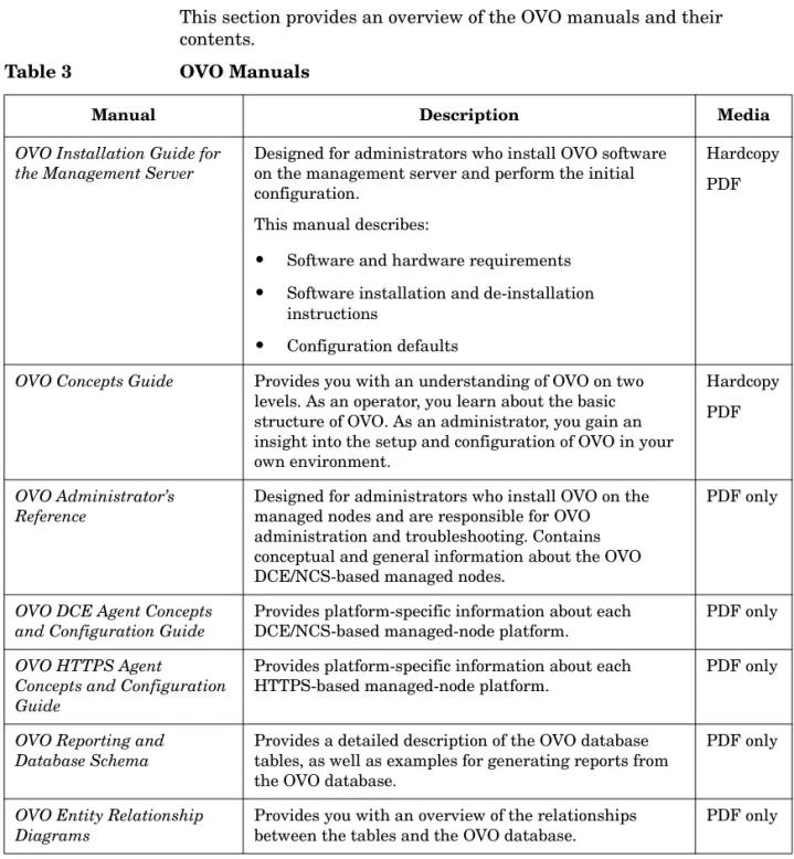
This section provides an overview of the OVO manuals and their contents.
Table 3 OVO Manuals
Manual Description Media
OVO Installation Guide for the Management Server
Designed for administrators who install OVO software on the management server and perform the initial configuration.
This manual describes:
• Software and hardware requirements • Software installation and de-installation
instructions
• Configuration defaults
Hardcopy PDF
OVO Concepts Guide Provides you with an understanding of OVO on two levels. As an operator, you learn about the basic structure of OVO. As an administrator, you gain an insight into the setup and configuration of OVO in your own environment.
Hardcopy PDF
OVO Administrator’s Reference
Designed for administrators who install OVO on the managed nodes and are responsible for OVO administration and troubleshooting. Contains conceptual and general information about the OVO DCE/NCS-based managed nodes.
PDF only
OVO DCE Agent Concepts and Configuration Guide
Provides platform-specific information about each DCE/NCS-based managed-node platform.
PDF only
OVO HTTPS Agent
Concepts and Configuration Guide
Provides platform-specific information about each HTTPS-based managed-node platform.
PDF only
OVO Reporting and Database Schema
Provides a detailed description of the OVO database tables, as well as examples for generating reports from the OVO database.
PDF only
OVO Entity Relationship Diagrams
Provides you with an overview of the relationships between the tables and the OVO database.
OVO Java GUI Operator’s Guide
Provides you with a detailed description of the OVO Java-based operator GUI and the Service Navigator. This manual contains detailed information about general OVO and Service Navigator concepts and tasks for OVO operators, as well as reference and troubleshooting information.
PDF only
Service Navigator Concepts and Configuration Guide
Provides information for administrators who are responsible for installing, configuring, maintaining, and troubleshooting the HP OpenView Service Navigator. This manual also contains a high-level overview of the concepts behind service management.
Hardcopy PDF
OVO Software Release Notes Describes new features and helps you:
• Compare features of the current software with features of previous versions.
• Determine system and software compatibility. • Solve known problems.
PDF only
OVO Supplementary Guide to MPE/iX Templates
Describes the message source templates that are available for the MPE/iX managed nodes. This guide is not available for OVO on Solaris.
PDF only
Managing Your Network with HP OpenView Network Node Manager
Designed for administrators and operators. This manual describes the basic functionality of the HP OpenView Network Node Manager, which is an embedded part of OVO.
Hardcopy PDF
OVO Database Tuning This ASCII file is located on the OVO management server at the following location:
/opt/OV/ReleaseNotes/opc_db.tuning
ASCII
18
Additional OVO-related Products
This section provides an overview of the OVO-related manuals and their contents.
Table 4 Additional OVO-related Manuals
Manual Description Media
HP OpenView Operations for UNIX Developer’s Toolkit
If you purchase the HP OpenView Operations for UNIX Developer’s Toolkit, you receive the full OVO documentation set, as well as the following manuals:
OVO Application Integration Guide
Suggests several ways in which external applications can be integrated into OVO.
Hardcopy PDF OVO Developer’s Reference Provides an overview of all the available application
programming interfaces (APIs).
Hardcopy PDF HP OpenView Event Correlation Designer for NNM and OVO
If you purchase HP OpenView Event Correlation Designer for NNM and OVO, you receive the following additional documentation. Note that HP OpenView Event Correlation Composer is an integral part of NNM and OVO. OV Composer usage in the OVO context is described in the OS-SPI documentation.
HP OpenView ECS Configuring Circuits for NNM and OVO
Explains how to use the ECS Designer product in the NNM and OVO environments.
Hardcopy PDF
The following information is available online. Table 5 OVO Online Information
Online Information Description
HP OpenView Operations Administrator’s Guide to Online Information
Context-sensitive help system contains detailed help for each window of the OVO administrator Motif GUI, as well as step-by-step
instructions for performing administrative tasks. HP OpenView Operations
Operator’s Guide to Online Information
Context-sensitive help system contains detailed help for each window of the OVO operator Motif GUI, as well as step-by-step instructions for operator tasks.
HP OpenView Operations Java GUI Online
Information
HTML-based help system for the OVO Java-based operator GUI and Service Navigator. This help system contains detailed information about general OVO and Service Navigator concepts and tasks for OVO operators, as well as reference and troubleshooting information. HP OpenView Operations
Man Pages
Manual pages available online for OVO. These manual pages are also available in HTML format.
To access these pages, go to the following location (URL) with your web browser:
http://<management_server>:3443/ITO_MAN
In this URL, the variable <management_server> is the fully-qualified hostname of your management server. Note that the man pages for the OVO HTTPS-agent are installed on each managed node.
This preface describes online documentation for the HP OpenView Operations (OVO) Motif and the Java operator graphical user interfaces (GUIs).
Online Help for the Motif GUI
Online information for the HP OpenView Operations (OVO) Motif graphical user interface (GUI) consists of two separate volumes, one for operators and one for administrators. In the operator’s volume you will find the HP OpenView OVO Quick Start, describing the main operator windows.
Types of Online Help
The operator and administrator volumes include the following types of online help:
❏ Task Information
Information you need to perform tasks, whether you are an operator or an administrator.
❏ Icon Information
Popup menus and reference information about OVO icons. You access this information with a right-click of your mouse button.
❏ Error Information
Information about errors displayed in the OVO Error Information window. You can access context-sensitive help when an error occurs. Or you can use the number provided in an error message to perform a keyword search within the help system.
22
❏ Help Instructions
Instructions about the online help system itself for new users. ❏ Printing Facility
Printing facility, which enables you to print any or all topics in the help system. (An HP LaserJet printer or a compatible printer device is required to print graphics.)
To Access Online Help
You can access the help system in any of the following ways: ❏ F1 Key
Press F1 while the cursor is in any active text field or on any active button.
❏ Help Button
Click [Help] at the bottom of any window. ❏ Help Menu
Open the drop-down Help menu from the menu bar. ❏ Right Mouse Click
Click a symbol, then right-click the mouse button to access the Help menu.
You can then select task lists, which are arranged by activity, or window and field lists. You can access any topic in the help volume from every help screen. Hyperlinks provide related information on other help topics. You can also access context-sensitive help in the Message Browser and Message Source Templates window. After selecting Help: On Context from the menu, the cursor changes into a question mark, which you can then position over the area about which you want help. When you click the mouse button, the corresponding help page is displayed in its help window.
Navigator
The online help for the HP OpenView Operations (OVO) Java graphical user interface (GUI), including Service Navigator, helps operators to become familiar with and use the OVO product.
Types of Online Help
The online help for the OVO Java GUI includes the following information:
❏ Tasks
Step-by-step instructions. ❏ Concepts
Introduction to the key concepts and features. ❏ References
Detailed information about the product. ❏ Troubleshooting
Solutions to common problems you might encounter while using the product.
❏ Index
Alphabetized list of topics to help you find the information you need, quickly and easily.
Viewing a Topic
To view any topic, open a folder in the left frame of the online documentation window, then click the topic title. Hyperlinks provide access to related help topics.
24
Accessing the Online Help
To access the help system, select Help: Contents from the menu bar of the Java GUI. A web browser opens and displays the help contents.
NOTE To access online help for the Java GUI, you must first configure OVO to use your preferred browser.
Firewall Configuration in OVO About this Chapter
Chapter 1 26
About this Chapter
This chapter describes how to setup and configure OVO in a firewall environment. It describes what steps need to be performed on the OVO management server and on the firewall to allow communication to an agent outside of the firewall.
This document is not based on any specific firewall software. The configuration actions should be easy to adapt to any firewall software. Knowledge of OVO and firewall administration is required to understand this chapter.
Naming Conventions
Table 1-1 specifies the naming conventions that have been applied to the filter rules.
Table 1-1 Naming Conventions Used in Filter Rules
Name Definition
HTTPS NODE Managed node where a real HTTPS agent is available. DCE NODE Managed node where a real DCE agent is available. JAVA GUI System that has the Java GUI installed.
MGD NODE Managed node of any node type.
MGMT SRV OVO management server.
NCS NODE Managed node where an NCS agent is available. NT NODE Managed node running MS Windows.
PACKAGE IP Virtual IP address of the MC/ServiceGuard cluster node <n>. PERFORMANCE MANAGER System where HP OpenView Performance Manager is installed. PHYS IP NODE <n> Physical IP address of the MC/ServiceGuard cluster node <n>. PROXY System that serves as HTTP proxy.
REPORTER System where HP OpenView Reporter is installed. UX NODE Managed node running any kind of UNIX system.
OVO Communication Concepts
OVO Communication Concepts
HTTPS Agent and Management Server
Communication
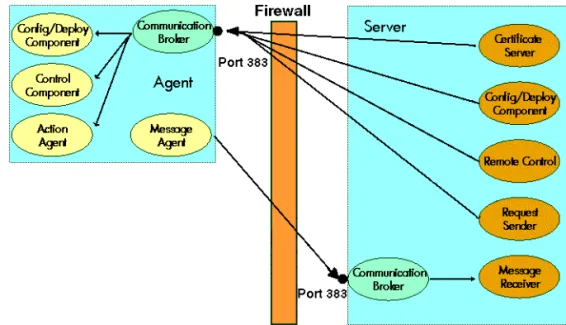
The basic communication model between OVO HTTPS agents and OVO management server is shown in Figure 1-1 below.
Figure 1-1 HTTPS Agent Components and Responsibilities at Runtime
Table on page 28 describes the communication processes shown in Agent software and valid certificates installed
Firewall Configuration in OVO OVO Communication Concepts
Chapter 1 28
For additional information on configuration of HTTPS agents, refer to the OVO HTTPS Agent Concepts and Configuration Guide.
Table 1-2 Communication Model Process Descriptions
Process Name Full Name Description
ovbbccb Communication Broker HTTPS-RPC server.
opcmsga Message Agent Sends outgoing messages to the server.
opcacta Action Agent
ovcd Control Component Controls the agents. Handles incoming requests.
ovconfd Configuration and Deployment component
Distribution data from the server.
ovcs Certificate server on OVO mangement server
Creates certificates and a private keys for authentication in secure communication.
opcmsgrb Message Receiver Receives incoming messages and action responses from the agents.
coda Embedded Performance Component
The embedded performance component collects performance counter and instance data from the operating system.
opcbbcdist Distribution Adapter Controls configuration deployment to HTTPS nodes.
opcragt Remote Agent Tool An RPC client that contacts the Endpoint Mapper and the Control Agent of all the agents.
ovoareqsdr Request Sender Sends outgoing requests to the agents. Handles the heartbeat polling.
OVO Communication Concepts
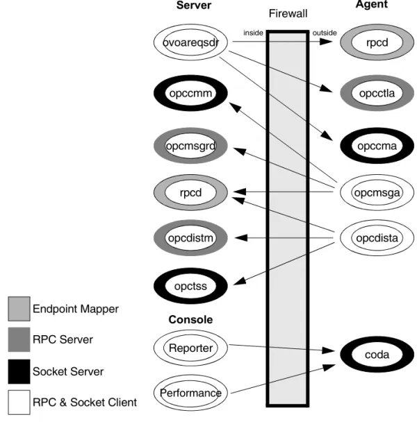
DCE Agent and Management Server Communication
The basic communication model between OVO agents and OVO management server is shown in Figure 1-2 below.Figure 1-2 Example Communications Model Process
ovoareqsdr
Firewall
inside outside
opccmm
Endpoint Mapper
RPC Server
Socket Server
opcmsgrd
rpcd
opcdistm
opctss
opcdista opcmsga
opccma opcctla
rpcd
Server
Console
Agent
Reporter
Firewall Configuration in OVO OVO Communication Concepts
Chapter 1 30
Table 1-3 Communication Model Process Descriptions
Process Name Full Name Description
coda Embedded Performance Component
The embedded performance component collects performance counter and instance data from the operating system.
opccma Communication Agent Handles bulk transfer requests from the server.
opccmm Communication Manager Handles bulk transfer requests from the agent.
opcctla Control Agent Controls the agents. Handles incoming requests.
opcdista Distribution Agent Pulls distribution data from the server.
opcdistm Distribution Manager Handles distribution requests from the agents.
opcmsga Message Agent Sends outgoing messages to the server.
opcmsgrd Message Receiver Receives incoming messages and action responses from the agents.
opctss TCP Socket Server Serves a TCP Socket connection for the distribution data.
ovoareqsdr Request Sender Sends outgoing requests to the agents. Handles the heartbeat polling.
rpcd RPC daemon This is the endpoint mapper.
opcragt Remote Agent Tool An RPC client that contacts the Endpoint Mapper and the Control Agent of all the agents.
Performance Manager
Performance Manager Graphical analysis and planning tool. It is designed to analyze and project future resource utilization and performance trends.
Reporter Reporter Management reporting tool that automatically transforms the data captured by OVO agents into management information.
OVO Communication Concepts
OVO Heartbeat Monitoring
There are different types of OVO heartbeat monitoring that can be configured per node in the OVO Node Bank.
❏ Normal
❏ RPC Only (for Firewalls) ❏ Agent Sends Alive Packets Normal Heartbeat Monitoring
If normal heartbeat monitoring is configured, the server first attempts to contact the node using ICMP packages. If this succeeds, it will continue to do the heartbeat monitoring using RPC calls. When an RPC call fails, it will use the ICMP packages to find out if, at least, the system is alive. As soon as this succeeds, the RPC calls are tried again.
RPC Only Heartbeat Polling (for Firewalls)
Since in firewall environments ICMP usually gets blocked, the RPC Only heartbeat monitoring option configures the server so that only RPC calls are used. Since RPC connections must be allowed through the firewall, this will work even if ICMP gets blocked.
The disadvantage is that in the event of a system outage, the network load is higher than with normal heartbeat monitoring because the RPC connection is still being tried.
Agent Sends Live Packets
By selecting this option, the agent can be triggered to send ICMP packages to the server reporting that the agent is alive. When such an alive package is received at the server, it will reset the polling interval there. If the polling interval expires without an alive package arriving, the server will start the usual polling mechanism as configured to find the agent’s status.
Firewall Configuration in OVO OVO Communication Concepts
Chapter 1 32
In a firewall environment this option is not advised for nodes outside the firewall because ICMP can get blocked there. For nodes inside the firewall this option is recommended since it will avoid RPC calls being made from the server to nodes inside the firewall and blocking ports.
Communication Types
Each OVO node can be configured to use a specific communication type. Most of the commonly used agent platforms support HTTPS and DCE. Some support their own communication types, for example, Microsoft Windows and Novell NetWare. Microsoft’s RPC implementation is mostly compatible to DCE, while for Novell NetWare nodes a special RPC stack is included.
The following communication types are supported: ❏ HTTPS/TCP
❏ DCE/UDP ❏ DCE/TCP ❏ Microsoft RPC ❏ Sun RPC
OVO Communication Concepts
HTTPS/TCP Communication
HTTPS 1.1 based communications is the latest communication technology used by HP OpenView products and allows applications to exchange data between heterogeneous systems.
OpenView products using HTTPS communication can easily
communicate with each other, as well as with other industry-standard products. It is also now easier to create new products that can
communicate with existing products on your network and easily integrate with your firewalls and HTTP-proxies.
HTTPS communication provides the following major advantages: • Firewall Friendly
• Secure • Open • Scalable
DCE/UDP Communication
Since UDP does not do any transmission control, communication packets can be lost on the network. DCE RPC’s, based on UDP, implement their own transmission control on a higher level of the communication stack. Therefore no communication can be lost.
Since UDP is not connection based, everything is cleaned up immediately after the communication is complete. This makes it the preferred choice for all nodes where the following applies:
❏ The node is located inside the firewall. See “DCE/UDP Communication Type” on page 82 for more information.
❏ The node is connected on a good LAN connection where few packets are lost.
Firewall Configuration in OVO OVO Communication Concepts
Chapter 1 34
problems in environments where communication is to multiple different targets, for example, OVO, because resources stay locked for a while. So, wherever possible, switch the node connection type to UDP.
Microsoft RPC Communication
Microsoft RPC’s are mostly compatible to DCE RPC’s. Therefore the notes on UDP and TCP apply.
For specific problems caused by Microsoft’s implementation see “Windows Managed Nodes” on page 80.
Sun RPC Communication
For Novell NetWare, the Sun RPC is used for communication. It can use UDP or TCP.
For specific problems caused on the implementation see “Sun RPC Communication Type” on page 83.
NCS Communication
NCS is a UDP based protocol implementing the transmission control on a higher level. For nodes only supporting NCS, there is no choice between UDP and TCP. See “NCS Communication Type” on page 83.
Configuring OVO for Firewall Environments
Configuring OVO for Firewall Environments
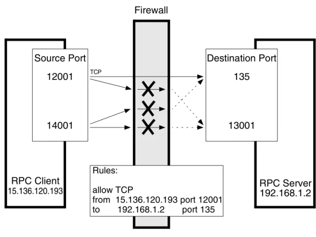
A firewall is a router system that filters all communication between two subnets. Only packets that pass at least one filter rule are allowed to pass the firewall. All other packets are discarded.A filter rule usually consists of the protocol type (for example TCP, UDP and ICMP), a direction (inside->outside or outside->inside), a source port and a destination port. Instead of one port, a port range can be specified. Figure 1-3 Example of a firewall configuration
Firewall
RPC Server
Destination Port
RPC Client
Source Port
Rules:
allow TCP
from 15.136.120.193 port 12001
to
192.168.1.2
port 135
12001
14001
135
13001
15.136.120.193
192.168.1.2
Firewall Configuration in OVO Special Configurations
Chapter 1 36
Special Configurations
Motif User Interface
It is advised that the Motif GUI is not directed through the firewall; this can cause security exposure problems. If this is required refer to your standard instructions on redirecting the X-Windows system through a firewall.
OVO Java User Interface
After the installation, the Java GUI requires only one TCP connection for the runtime. This port number can be configured. The default port number is 2531 for the Java GUI and 35211 for the Secure Java GUI. The firewall must be configured to allow the Java GUI access to the management server ports listed in Table 1-4.
Configuring Ports for the Java GUI or Secure Java GUI
Note that the port settings on the management server and the Java GUI client (or Secure Java GUI client) must be identical.
1.Configuring the Port on the Management Server: a. In the file /etc/services, locate the following line:
• Java GUI
ito-e-gui 2531/tcp # ITO Enterprise Java GUI-e-gui • Secure Java GUI
ito-e-gui-sec 35211/tcp # ITO Enterprise Secure Java GUI
Table 1-4 Filter Rule for the OVO Java GUI
Source Destination Protocol Source Port
Destination Port
JAVA GUI MGMT SRV TCP any 2531
Special Configurations
b. Change the port number 2531 or 35211 to the port number you wish to use.
c. Restart the inet.d service:
/usr/sbin/inetd –c
2.Configuring the Port on the Java GUI/Secure Java GUI Client:
Edit the GUI startup script ito_op (UNIX) or ito_op.bat (Windows) and add the following line:
port=<port_number>
Firewall Configuration in OVO Special Configurations
Chapter 1 38
Message Forwarding
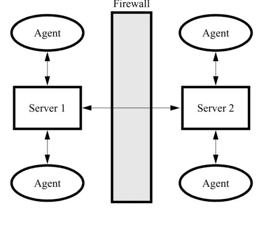
It is strongly recommend not to have OVO management servers outside a firewall to the Internet.
However, in many environments there are firewalls within a company causing multiple management servers with message forwarding to be set up. Figure 1-4 illustrates the Internet firewall for a message forwarding scheme.
Figure 1-4 Internet Firewall for Message Forwarding
Agent
Agent
Server 1
Agent
Agent
Server 2
Firewall
Special Configurations
Communication Concepts in Message Forwarding
Figure 1-5 on page 39 illustrates the communication model between two OVO management servers.
In Figure 1-5, the RPC daemon (rpcd) represents the endpoint mapper. The Message Receiver (opcmsgrd) receives incoming messages and action responses from agents and other management servers. The Forward Manager (opcforwm) forwards messages to other management servers.
Figure 1-5 Communication Between Two OVO Management Servers
opcforwm
Firewall
Endpoint Mapper
RPC Server
RPC Client
opcmsgrd
rpcd
opcforwm
opcmsgrd
rpcd
Firewall Configuration in OVO Special Configurations
Chapter 1 40
Configuring Message Forwarding in Firewall Environments When configuring message forwarding between OVO management servers, each management server must be configured in the other’s node bank. The communication type should be configured to use DCE/TCP. The firewall must be configured agains the rules specified in Table 1-5.
NOTE Message forwarding between OVO management servers is based on DCE communication.
These rules allow only the forwarding of messages and the
synchronization of the two management servers. As soon as actions are executed on an agent system on the other side of the firewall, the agent rules must be applied to the firewall as described inChapter 4,
“Configuring DCE Nodes,” on page 67.
Table 1-5 DCE/TCP Filter Rules for Multiple Management Servers
Source Destination Protocol Source Port Destination
port Description
SERVER 1 SERVER 2 TCP 12004-12005 135 Endpoint map SERVER 2 SERVER 1 TCP 12004-12005 135 Endpoint
map SERVER 1 SERVER 2 TCP 12004-12005 12001 Message
Receiver SERVER 2 SERVER 1 TCP 12004-12005 12001 Message
Special Configurations
VP390/VP400 in Firewall Environments
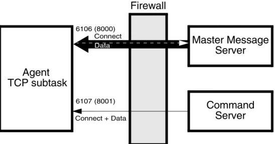
VP390 and VP400 consists of an agent component that runs on the mainframe and a server component that handles all communication between agent and server as shown in Figure 1-6.
The agent TCP subtask requests the opening of two TPC/IP ports on the mainframe, then waits for the VP390/VP400 server component to start communication through these ports. All connections between these components are initiated from the server but data may be sent from the agent to the server (in the same way as messages being sent to the message server). The communication is based on TCP sockets. Figure 1-6 Firewall for VP390(VP400)
Agent
Master Message
Firewall
Command
TCP subtask
Server
Server
6106 (8000)
6107 (8001) Connect + Data
Data
Firewall Configuration in OVO Special Configurations
Chapter 1 42
The two connection ports by default are 6106 (for messages) and 6107 (for commands). To change the defaults follow the instructions below: ❏ Changing the Default Ports on the Managed Node
The ports are defined in the VPOPARM member of the SAMP dataset which is loaded into the mainframe at installation time. To change the ports, edit the SAMP(VPOPARM) member. The comments in VPOPARM refer to these two ports as the MMSPORT and the CMDPORT. To edit defaults on the agent, enter the text below:
VP390 TCP 6106 6107
VP400 TCP 8000 8000
Refer to HP OpenView Operations OS/390 Management Concepts Guide for additional information.
❏ Changing the Default Ports on the Management Server VP390 Specify the new values in the
EVOMF_HCI_AGENT_PORT and EVOMF_CMDS_AGENT_PORT values. VP400 Specify the new values in the
EV400_AS400_MSG_PORT and EV400_AS400_CMD_PORT values.
The firewall must be configured for the ports specified in Table 1-6. Table 1-6 Filter Rules for VP390
Source Destination Protocol Source Port
Destination
port Description
SERVER VP390 TCP any 6106 Messages
SERVER VP390 TCP any 6107 Commands
SERVER VP400 TCP any 8000 Messages
Network Address Translation
Network Address Translation
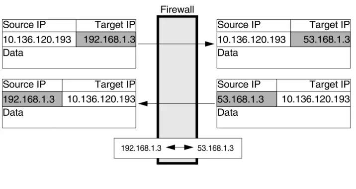
Network address translation (NAT) is often used with firewall systems in combination with the port restrictions. It translates IP addresses that are sent over the firewall.
Network address translation can be used to achieve the following: • Hide the complete IP range of one side of the firewall from the other
side.
• Use an internal IP range that cannot be used on the Internet, so it must be translated to a range that is available there.
NAT can be set up to translate only the IP addresses of one side of the firewall or to translate all addresses as shown in Figure 1-7.
Figure 1-7 Firewall using NAT
Firewall
192.168.1.3 53.168.1.3
Source IP
Target IP
Data
10.136.120.193
192.168.1.3
Source IP
Target IP
Data
10.136.120.193
53.168.1.3
Source IP
Target IP
Data
192.168.1.3
10.136.120.193
Source IP
Target IP
Data
Firewall Configuration in OVO Network Address Translation
Chapter 1 44
Address Translation of Duplicate Identical IP Ranges
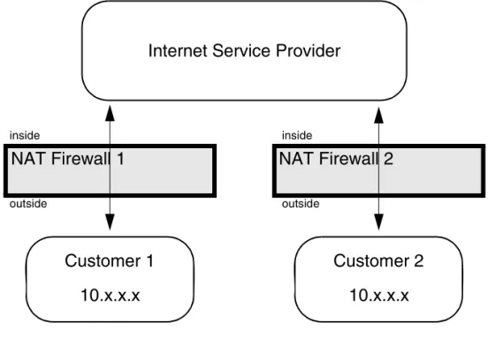
Figure 1-8 illustrates Address Translation firewall for duplicate identical IP ranges.Figure 1-8 Address Translation Firewall for Duplicate Identical IP Ranges
This scenario often happens for Internet Service Providers (ISPs). They have multiple customers using the same IP range internally. To manage all customers, they set up an Address Translation firewall for each. After the translation the systems at all customers have unique IP addresses on the ISP’s network.
OVO can handle this scenario by using the unique IP address for all communication. This means that the OVO agent on a customer’s system uses the IP address as known on the ISP side of the firewall for the OVO internal communication.
NAT Firewall 1
NAT Firewall 2
Internet Service Provider
Customer 1
Customer 2
10.x.x.x
10.x.x.x
inside
outside
inside
Network Address Translation
Known Issues in NAT Environments
In a NAT environment, the following problems can be encountered. FTP Does Not Work
Problem
There is a general problem with FTP in a NAT environment. This will cause the OVO agent installation mechanism to fail. The following scenarios might occur:
❏ The Installation to Microsoft Windows nodes just hangs for a while after entering the Administrator’s password.
❏ The UNIX installation reports that the node does not belong to the configured operating system version.
This issue can be verified by manually trying FTP from the OVO management server to an agent outside the firewall. The FTP login will succeed but at the first data transfer (GET, PUT, DIR), FTP will fail. Possible error messages are:
500 Illegal PORT Command
425 Can’t build data connection: Connection refused. 500 You’ve GOT to be joking.
425 Can’t build data connection: Connection refused. 200 PORT command successful.
hangs for about a minute before reporting
425 Can’t build data connection: Connection timed out.
Usually, FTP involves opening a connection to an FTP server and then accepts a connection from the server back to the client on a
randomly-chosen, high-numbered TCP port. The connection from the client is called the control connection, and the one from the server is known as the data connection. All commands and the server’s responses
Firewall Configuration in OVO Network Address Translation
Chapter 1 46
Solution
The HP-UX FTP client does not support passive FTP. As a result, for OVO, installation using FTP cannot be used. Manually install the agent on the managed node system. Use the SSH installation method, provided that SSH can cross the firewall.
Advanced Configuration Special Configurations
Chapter 2 48
Special Configurations
ICMP (DCE Agents Only)
Since ICMP packages are usually blocked over the firewall, there is a trigger for the agent to disable any ICMP requests to the server. To enable that special functionality, add the following line to the opcinfo file and restart the agents:
OPC_RPC_ONLY TRUE
DNS
If DNS queries are blocked over the firewall, local name resolution has to be set up so that the agent can resolve its own and the OVO management server’s name.
SNMP Queries
If SNMP queries are blocked over the firewall, no automatic
determination of the node type when setting up a node is possible. For all nodes outside the firewall, the correct node type has to be selected manually.
If SNMP queries are wanted over the firewall, the following ports have to be opened up as displayed in Table 2-1:
Table 2-1 Filter Rules for SNMP Queries
Source Destination Protocol Source Port Destination Port Description
MGMT SRV MGD NODE UDP any 161 SNMP
Special Configurations
OVO Agent Installation in Firewall Environments
In most firewall environments, the agents will be installed manually and will not use the automatic OVO agent installation mechanism. If the automatic agent installation is required for the firewall, the following ports need to be opened:❏ Windows: Table 2-2 on page 49 ❏ UNIX: Table 2-3 on page 50
The installation of Windows managed nodes might fail and report the following message:
E-> Connection error to management server hpbblcsm.bbn.hp.com.
E-> Error from InformManager. E-> Setup program aborted.
If this occurs, it is related to the firewall blocking that communication. As a workaround, install the agents manually as described in the OVO Administrator’s Reference. In general, you will need to execute the opc_pre.bat script instead of the opc_inst.bat script. In addition, execute the following commands on the management server:
Table 2-2 Filter Rules for Windows Agent Installation
Source Destination Protocol Source Port
Destination
Port Description MGMT SRV NT NODE ICMP echo
request
n/a n/a ICMP
NT NODE MGMT SRV ICMP echo request
n/a n/a ICMP
MGMT SRV NT NODE TCP any 21 FTP
Advanced Configuration Special Configurations
Chapter 2 50
Table 2-3 specifies filter rules for UNIX managed nodes.
NOTE The installation of UNIX managed nodes will run into a timeout of about one minute when checking the password. This can only be avoided by completely opening the firewall.
Table 2-3 Filter Rules for UNIX Agent Installation
Source Destination Protocol Source Port Destination
Port Description MGMT SRV UX NODE ICMP echo
request
n/a n/a ICMP
UX NODE MGMT SRV ICMP echo request
n/a n/a ICMP
MGMT SRV UX NODE TCP any 21 FTP
UX NODE MGMT SRV TCP 20 any FTP-Data
MGMT SRV UX NODE TCP any 512 Exec
MGMT SRV UX NODE TCP any 22 Exec
Configuring HTTPS Nodes
Chapter 3 52
This chapter describes how to setup and configure OVO HTTPS managed nodes in a firewall environment. It describes what steps need to be performed on the OVO management server and on the firewall to allow communication to an agent outside of the firewall.
Specifying Client Port Ranges
Specifying Client Port Ranges
To specify client port ranges for HTTPS nodes on the OVO management server, use the following command:
ovconfchg -ovrg server -ns bbc.http -set CLIENT_PORT <range>
This command set the specified port range for all HTTPS nodes managed by the OVO management server from which the command is called. A port range can be set for a specific processes. For example, to set a port range for the request sender, ovoareqsdr use the following command:
ovconfchg -ovrg server -ns bbc.http.ext.ovoareqsdr -set \ CLIENT_PORT <range>
Configuring HTTPS Nodes
Management Server and Managed Node Port Settings
Chapter 3 54
Management Server and Managed Node Port
Settings
For both, OVO management server and OVO managed node, a set of ports can be defined. The following settings are used, as an example, within this documentchapter. The settings can be changed to reflect the your environment.
Table 3-1 specifies the management server communication ports.
Table 3-2 specifies the managed node communication ports.
Table 3-3 specifies the console communication ports. Table 3-1 Management Server Communication Port Settings
Server Type Communication Type Port Range
ovbbccb HTTPS Server 383
Remote Agent Tool HTTPS Client ANY, Configurable Request Sender HTTPS Client ANY, Configurable opcbbcdist HTTPS Client ANY, Configurable
ovcs HTTPS Client ANY, Configurable
Table 3-2 Managed Node Communication Port Settings
Agent Type Communication Type Port Range
ovbbccb HTTPS Server 383
Message Agent HTTPS Client ANY, Configurable
Table 3-3 Console Communication Port Settings
Agent Type Communication Type Port Range Reporter (3.5) HTTPS Client ANY, Configurable Performance Manager
(4.0.5)
Configuring a Firewall for HTTPS Nodes without a Proxy
Configuring a Firewall for HTTPS Nodes
without a Proxy
For the runtime of the OVO agent, the firewall requires a specific range of communication ports to be opened. This allows the use of normal agent functionality. For details on the agent installation, see “OVO Agent Installation in Firewall Environments” on page 49.
Table 3-4 specifies the filter rules for runtime of HTTPS managed nodes. Figure 3-1 Firewall for HTTPS Nodes without a Proxy
Firewall
Server
Agent 1
Agent 2
Agent n
Server Domain External Domain svr.dom ext.dom
Table 3-4 Filter Rules for Runtime of HTTPS Managed Nodes without Proxies
Configuring HTTPS Nodes
Configuring a Firewall for HTTPS Nodes with Proxies
Chapter 3 56
Configuring a Firewall for HTTPS Nodes with
Proxies
For the runtime of the OVO agent with HTTP proxy, the firewall requires a specific range of communication ports to be opened. This allows the use of normal agent functionality. For details on the agent installation, see “OVO Agent Installation in Firewall Environments” on page 49. Figure 3-2 Firewall for HTTPS Nodes with an External Proxy
Firewall
Server
Server Domain External Domain
❶
ovconfchg -ns bbc.http -set PROXY p.ext.dom:pport+(*.ext.dom)❷
ovconfchg -ns bbc.http -set PROXY p.ext.dom:pport+(s.svr.dom)svr.dom ext.dom
❶
Proxy
Agent 1
Agent 2
Agent n
❷
❷
❷
Table 3-5 Filter Rules for Runtime of HTTPS Managed Nodes with an External Proxy
Source Destination Protocol Source Port Destination Port MGMT SRV Proxy TCP ANY, Configurablea Proxy port
Proxy MGMT SRV TCP PROXY, dependent on
software
Configuring a Firewall for HTTPS Nodes with Proxies
Proxies can be configured using the command:
ovconfchg -ns bbc.http -set PROXY
Table 3-4 specifies the filter rules for runtime of HTTPS managed nodes. Figure 3-3 Firewall for HTTPS Nodes with an Internal Proxy
Proxy
Firewall
Server
Agent 1
Agent 2
Agent n
Server Domain External Domain
❶
ovconfchg -ns bbc.http -set PROXY p.ext.dom:pport+(*.ext.dom)❷
ovconfchg -ns bbc.http -set PROXY p.ext.dom:pport+(s.svr.dom)svr.dom ext.dom
❷
❷
❷
❶
Table 3-6 Filter Rules for Runtime of HTTPS Managed Nodes with an Internal Proxy
Configuring HTTPS Nodes
Configuring a Firewall for HTTPS Nodes with Proxies
Chapter 3 58
Figure 3-4 Firewall for HTTPS Nodes with Internal and External Proxies
Proxy
Firewall
Server
Agent 1
Agent 2
Agent n
Server Domain External Domain
❶
ovconfchg -ns bbc.http -set PROXY p.ext.dom:pport+(*.ext.dom)❷
ovconfchg -ns bbc.http -set PROXY p.ext.dom:pport+(s.svr.dom)svr.dom ext.dom
❷
❷
❷
❶
Proxy
Table 3-7 Filter Rules for Runtime of HTTPS Managed Nodes with Internal and External Proxies
Source Destination Protocol Source Port Destination Port Proxy Internal Proxy External TCP PROXY internal ,
dependent on software
PROXY external , dependent on software Proxy External Proxy Internal TCP PROXY srv.domain,
dependent on software
PROXY internal , dependent on software
Configuring the OVO Management Server
Configuring the OVO Management Server
To configure the management server, complete the following steps:1.Configure Management Server (ovbbccb) Port Enter the command:
ovconfchg -ovrg server -ns bbc.cb.ports \ -set SERVER_PORT <Destination_Port/CB_Port> 2.Configure the Client Port Range
Enter the following commands:
ovconfchg -ns bbc.cb.ports \
-set CLIENT_PORT <Source_Port_Range> 3.Restart the management server processes.
a. ovstop ovctrl ovoacomm
b. ovstart opc
4.Optional: Improve network performance.
Check if the network parameters for the system require tuning. Refer to “Network Tuning for HP-UX 11.x” on page 164 or to “Network Tuning for HP-UX 10.20” on page 163.
Configuring HTTPS Nodes
Configuring OVO Managed Nodes
Chapter 3 60
Configuring OVO Managed Nodes
The communication type for each node has to be set in the OVO Node Bank on the management server. After distribution of the new
configuration data, the agent processes have to be restarted manually. 1.Configure the Server Port
Enter the command:
ovconfchg -ovrg server -ns bbc.cb.ports \ -set SERVER_PORT <Destination_Port/CB_Port> 2.Configure the Client Port Range
Enter the command:
ovconfchg -ns bbc.cb.ports \
-set CLIENT_PORT <Source_Port_Range>
3.Restart the Agent Processes on the Managed Node. Restart the agent processes for the new settings to take effect:
opcagt -kill opcagt -start
Systems with Multiple IP Addresses
Systems with Multiple IP Addresses
If your environment includes systems with multiple network interfaces and IP addresses and you want to use a dedicated interface for the HTTP-based communication, set the following variables:
❏ CLIENT_BIND_ADDR
ovconfchg -ns bbc.http -set CLIENT_BIND_ADDR <address>
See “CLIENT_BIND_ADDR” on page 174 for more information. For the specific processes, such as for the OVO Message Agent, use the command:
ovconfchg -ns bbc.http.ext.opcmsga -set \ CLIENT_BIND_ADDR <addr>
❏ SERVER_BIND_ADDR
ovconfchg -ns bbc.http -set SERVER_BIND_ADDR <address>
See “SERVER_BIND_ADDR” on page 173 for more information. This command applies to the Communication Broker (ovbbccb) and all other HTTPS RPC servers visible on the network. Since for OVO 8.x, only the Communication Broker is normally visible on the network, all other RPC servers are connected through the
Communication Broker and are not effected by SERVER_BIND_ADDR setting.
Configuring HTTPS Nodes
HTTPS Agents and Network Address Translation
Chapter 3 62
HTTPS Agents and Network Address
Translation
Address Translation of Outside Addresses
This is the basic scenario for NAT. Only the outside addresses are translated at the firewall. An example of the environment is shown in Figure 3-5.
Figure 3-5 Firewall Using NAT
DNS
bear.int.mycom.com 10.136.120.193
NAT Firewall
Agent
Server
10.136.120.193
53.168.1.3
192.168.1.3 53.168.1.3
OPC_IP_ADDRESS
bear.int.mycom.com lion.ext.mycom.com
lion.ext.mycom.com 192.168.1.3 DB
192.168.1.3
HTTPS Agents and Network Address Translation
NOTE If SSH works through the firewall, agent installation using the OVO Administrtator’s UI is possible. However, you must manually map the certificate request to the node and grant the request.
Address Translation of Inside Addresses
In this scenario, only the inside address (the management server) is translated at the firewall. An example of the environment is shown in Figure 3-6.
Figure 3-6 Network Address Translation for an Address Inside the Firewall
Firewall
10.136.120.193 35.136.120.193 inside outside
Agent
53.168.1.3
OPC_IP_ADDRESS
lion.ext.mycom.com
192.168.1.3
Server
10.136.120.193
bear.int.mycom.com
lion.ext.mycom.com 192.168.1.3 DB
Configuring HTTPS Nodes
HTTPS Agents and Network Address Translation
Chapter 3 64
Address Translation of Inside and Outside Addresses
This is the combination of the two previous scenarios. The inside and the outside network have a completely different set of IP addresses that get translated at the firewall. An example of the environment is shown in Figure 3-7.Figure 3-7 Network Address Translation for Addresses Inside and Outside the Firewall
Firewall
192.168.1.3 53.168.1.3 10.136.120.193 35.136.120.193
DNS
bear.int.mycom.com 10.136.120.193
DNS
bear.int.mycom.com 35.136.120.193 inside outside
Server
10.136.120.193
bear.int.mycom.com
lion.ext.mycom.com 192.168.1.3 DB
Agent
53.168.1.3
OPC_IP_ADDRESS
lion.ext.mycom.com
HTTPS Agents and Network Address Translation
IP Masquerading or Port Address Translation
IP Masquerading or Port Address Translation (PAT) is a form of Network Address Translation that allows systems that do not have registered Internet IP addresses to have the ability to communicate to the Internet via the firewall system’s single Internet IP address. All outgoing traffic gets mapped to the single IP address which is registered at the Internet. This can be used to simplify network administration.The administrator of the internal network can choose reserved IP addresses (for example, in the 10.x.x.x range, or the 192.168.x.x range). These addresses are not registered at the Internet and can only be used internally. This also alleviates the shortage of IP addresses that ISPs often experience. A site with hundreds of computers can get by with a smaller number of
registered Internet IP addresses, without denying any of it’s users Internet access.
The disadvantage of this method is that protocols that return
connections collapse because there are multiple machines hiding behind that address; the firewall does not know where to route them.
It is necessary to use “port forwarding” to reach the agents from inside the firewall. The proxy setting must be made as follows:
ovconfchg -ovrg server -ns bbc.http -set \ PROXY “10.136.120.254:Pfw + (*.ext.mycom.com)”
Configuring HTTPS Nodes
HTTPS Agents and Network Address Translation
Chapter 3 66
An example of IP Masquerading is shown in Figure 3-8. Figure 3-8 IP Masquerading or Port Address Translation
NAT Firewall Masquerading
53.168.1.3 10.136.120.254 53.168.1.4 inside outside
Server
10.136.120.193
bear.int.mycom.com lion.ext.mycom.com 53.168.1.3 DBAgent
53.168.1.3
OPC_IP_ADDRESS lion.ext.mycom.com 53.168.1.3Agent
53.168.1.4
OPC_IP_ADDRESS tiger.ext.mycom.com 53.168.1.410.136.120.254
tiger.ext.mycom.com 53.168.1.4Proxy
53.168.1.100
OPC_IP_ADDRESS puma.ext.mycom.com 53.168.1.100Pfw Firewall port Ppx Proxy port
Configuring DCE Nodes
Chapter 4 68
This chapter describes how to setup and configure DCE managed nodes in a firewall environment. It describes what steps need to be performed on the OVO management server and on the firewall to allow
Management Server and Managed Node Port Settings
Management Server and Managed Node Port
Settings
For both, OVO management server and OVO managed node, a set of ports must be defined. The following settings are used, as an example, within this chapter. The settings can be changed to reflect the your environment.
Table 4-1 specifies the management server communication ports. Table 4-1 Management Server Communication Port Settings
Server Type Communication Type Port Range Communication Manager Socket Server 12003
Display Manager RPC Server 12000
Distribution Manager RPC Server 12002 Forward Manager RPC Client 12004-12005
Message Receiver RPC Server 12001
NT Virtual Terminal Socket Server 12061 Remote Agent Tool RPC Client 12041-12050
Request Sender RPC Client 12006-12040
Configuring DCE Nodes
Management Server and Managed Node Port Settings
Chapter 4 70
Table 4-2 specifies the managed node communication ports.
Table 4-3 specifies the console communication ports.
NOTE For details on the sizing of the RPC Client ranges on the OVO managed nodes and OVO management server, see “Port Usage on Managed Nodes” on page 191 and “Port Usage on the Management Server” on page 155. Table 4-2 Managed Node Communication Port Settings
Agent Type Communication Type Port Range Communication Agent Socket Server 13007
Control Agent RPC Server 13001
Distribution Agent RPC Client 13011-13013 Embedded Performance
Component
Socket Server 13010
Message Agent RPC Client 13004-13006
NT Virtual Terminal Socket Client 13008-13009
Table 4-3 Console Communication Port Settings
Agent Type Communication Type Port Range
Reporter Socket Client 14000-14003
Management Server and Managed Node Port Settings
In the configuration examples listed in this document, DCE/TCP is used as the communication type.
For further details on: ❏ DCE/UDP
See “DCE/UDP Communication Type” on page 82. ❏ Other Communication Types
See “NCS Communication Type” on page 83 for NCS usage and “Sun RPC Communication Type” on page 83 for Sun RPC usage.
❏ Supported Communication Types for Each Agent Platform See the VPO Installation Guide for the Management Server.
Configuring DCE Nodes
Configuring a Firewall for DCE Nodes
Chapter 4 72
Configuring a Firewall for DCE Nodes
For the runtime of the OVO agent, the firewall requires a specific range of communication ports to be opened. This allows the use of normal agent functionality. For details on the agent installation, see “OVO Agent Installation in Firewall Environments” on page 49.
Table 4-4 specifies the filter rules for runtime of DCE managed nodes. Table 4-4 Filter Rules for Runtime of DCE Managed Nodes
Source Destination Protocol Source Port Destination
Port Description MGMT SRV DCE NODE TCP 12006-12040
12041-12050
135 Endpoint map
DCE NODE MGMT SRV TCP 13011-13013 13004-13006
135 Endpoint map
MGMT SRV DCE NODE TCP 12006-12040 13001 13007
Control agent Communication agent
MGMT SRV DCE NODE TCP 12041-12050 13001 Control agent DCE NODE MGMT SRV TCP 13011-13013 12002 Distribution
manager DCE NODE MGMT SRV TCP 13004-13006 12001
12003
Message receiver Communication manager