Please cite this article as: H. Kazemi moghadam, R. Shafaghat, A. Hajiabadi, Foil Application to Reduce Resistance of Catamaran under High Speeds and Different Operating Conditions, International Journal of Engineering (IJE), IJE TRANSACTIONS A: Basics Vol. 32, No. 01, (January 2019) 106-111
International Journal of Engineering
J o u r n a l H o m e p a g e : w w w . i j e . i r
Foil Application to Reduce Resistance of Catamaran under High Speeds and
Different Operating Conditions
H. Kazemi moghadam, R. Shafaghat*, A. Hajiabadi
Sea Based Energy Research Group, Babol Noshirvani University of Technology, Babol, Iran
P A P E R I N F O
Paper history: Received 11 June 2018
Received in revised form 19 November 2018 Accepted 03 January 2019
Keywords:
Catamaran Hydrofoil Load Conditions Towing Tank Drag Reduction
A B S T R A C T
Today, researchers exploit hybrid craft more than they used to be. The main reason is that they need to high speed as well as extra portability. For instance, a famous hybrid craft is named Hysucat, was designed through the combination of catamaran and hydrofoil. Catamarans, a type of multihull boats, have always considered by designers because of their simultaneous supply of high speed and stability. These boats hold high drag despite more wetted surface as well. By using hydrofoil the wetted surface reduces, and then the drag of boat will decline. Meanwhile, sketches in the layout of hydrofoil processes notice to weight and center of gravity. This paper investigated application of hydrofoil in the high speed catamaran with considering different conditions in terms of center of gravity and load conditions. The model has exploited in the three states of loading (partial, ballast and over) and two centers of gravity for each diverse weight. Hence, nine series tests in towing tank have been carried out on the model boat in scale 1 ratio to 11.43. Eventually, results were computed to full scale boat by Froude number and ITTC model. According to the test results, usage of the hydrofoil brings about 50% drag reduction.
doi: 10.5829/ije.2019.32.01a.14
1. INTRODUCTION1
High speed hulls play an important role in transportation and other specific industry. Multihull crafts are one of the most all-purpose high speed hulls. These hulls, due to their simultaneous supply of high-speed and sea-keeping have been always considered by the designers. Catamaran and Trimaran are kinds of multihulls which contain transversal stability and a large deck. The shape of their hulls make the flow easily round the body and pass through it. However on the other hand, the wetted surface of these hulls are a lot, in comparison with the usual kind of the mono hull. The resistance of catamaran is about 25% more than a mono hull [1]. In fact, Trimaran hulls, like Bladerunner, reduce drag about 20% lower than a mono hull [2, 3]. Catamaran's unique features and widespread usage, made lots of researchers investigate the ways of drag reduction.
Insel and Molland [4] through a numerical and experimental study investigated impact of semi-hull
*Corresponding Author Email: [email protected] (R. Shafaghat)
when the hydrofoil is mounted and designed adequately. Hoppe [1] planned and manufactured the first catamaran with hydrofoil, the author managed to diminish the boat resistance greatly through installing hydrofoil into its body. The reduction of drag led to ascending the maximum speed and descending fuel consumption. Despite plenty of accomplished researches in this scope, since some major problems including rapid conversions of trim and lack of stability in high speed, the outcomes were not efficient. However, there have been the prospered researches such as Migeotte et al. [17], Milandri [18], Grobler [19], Sahoo et al. [20], Köpke [21], Homma and Frouws [22], Swidan et al. [23] and Hajiabadi et al. [24].
Loading conditions effect on stability and operation of the boat, because the design of hydrofoil is processed notice to weight and center of gravity. In this paper, exploiting of hydrofoil on the catamaran boat in the three varied loading conditions was investigated.
2. MODEL
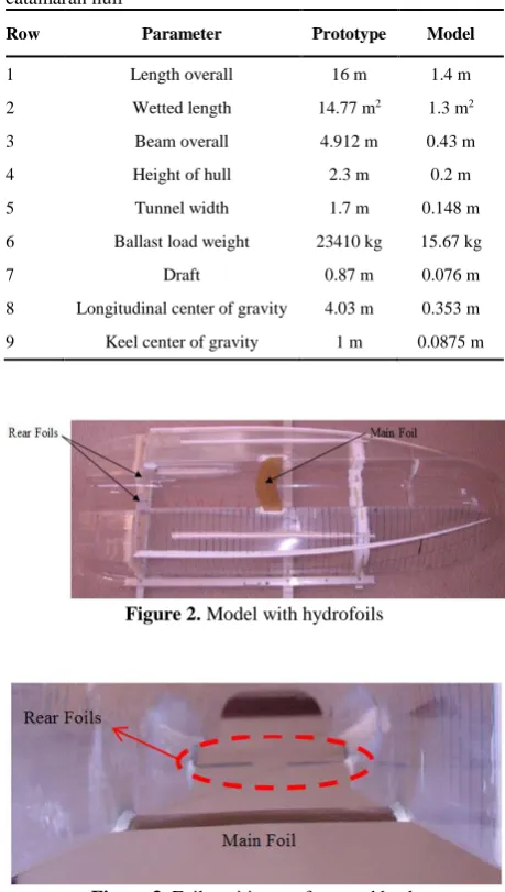
In this study, catamaran with asymmetric hull was studied. In Figure 1, the body plan of hull is displayed. The length of boat is 16 m and weight of boat in partial load 20.3 tons, in ballast load 23.41 tons and over load 25.6 tons were assumed. A model of the catamaran in a scale of 1 in 11.43 was built according to the top speed of the boat coincided with the top speed of the towing carriage. The details of the model are given in the Table 1. The foil pattern is based on the principles of the standard design hydrofoil boat, which uses a main foil just forward of the LCG and two small rear foils aft of the LCG. Figure 2 shows a picture of the model and Figure 3 gives the foil positions as tested. The foil is positioned on the keel with the flanges connecting to the hull recessed into the keel so that there is no disturbance to the flow and the hull-foil connection point. Inside corners also were radiused to reduce interference drag.
Figure 1. Body plan of asymmetric catamaran hull
TABLE 1. Model and scale dimensions of asymmetric catamaran hull
Row Parameter Prototype Model
1 Length overall 16 m 1.4 m
2 Wetted length 14.77 m2 1.3 m2
3 Beam overall 4.912 m 0.43 m
4 Height of hull 2.3 m 0.2 m
5 Tunnel width 1.7 m 0.148 m
6 Ballast load weight 23410 kg 15.67 kg
7 Draft 0.87 m 0.076 m
8 Longitudinal center of gravity 4.03 m 0.353 m
9 Keel center of gravity 1 m 0.0875 m
Figure 2. Model with hydrofoils
Figure 3. Foil positions at front and back
The main foil (EPPLER 385) has a chord of 0.7 m and the profile thickness is 7% of the chord and the rear foil (EPPLER 385) has a chord length of 0.421 m and a span of 0.597 m. The foil pattern was designed by the use of computerized mathematical and a load distribution of 50% foil load and 50% hull load was anticipated for the top speed of 52 knot under ballast load conditions. The load ratio between foils and hull depends on many factors and normally varies between 40-60% from common applications.
3. TOWING TANK
Table 2. The frequency controlled electric drive system can bring the trolley up to speeds of 8.0 m/s. The model is attached to the trolley via a bridle system which is attached to a load cell with a computerized data acquisition system. Sinkage or rise of the bow and stern are also registered and allow the trim angle at speed to be determined. Tests were conducted with the model running behind an air screen to prevent the air drag component from influencing the correlation calculation. The prototype air drag is calculated separately and added to the total resistance assuming an air drag coefficient CD air = 0.6 (half streamlined body) and for the frontal area of the catamaran of Afrontal = 14.7 m2.
3. 1. Uncertainty A full investigation of the uncertainty involving multiple installations and ballasting of the model was not performed. However calculation based on uncertainty components identified as dominant in previous studies; in this facility using this towing arrangement and dynamometer suggested that the bias limit on the total resistance coefficient at model scale is of the order of 1% at a speed corresponding to 50 knots full scale. Even then it should be noted that the dominant sources of bias do not in any case affect comparisons between tests such as resistance changes between the model with and without foil. Multiple repeat tests carried out at this speed indicate that the corresponding precision of the total resistance coefficient was around 0.4%. Hence the total uncertainty is estimated at around 1%.
4. DESIGN OF EXPERIMENT
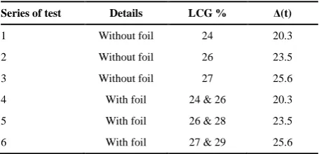
In order to investigate the loading conditions on resistance of the boat, 6 series of tests were considered. To be exact, in the tests the impact of both weight and center of gravity on the catamaran operation were noticed in two states, namely, with foil and not. Both of models have been inspected in the states of various loading (partial, ballast and over) as well as two center of gravity for each weight. Overall, 6 entire series of tests have accomplished, brief of them illustrated in Table 3.
TABLE 2. Details of towing tank
Size Details
90 m Length
5 m Wide
3 m Depth
8 m/s Trolley max speed
0.05 m/s Trolley min speed
TABLE 3. Details of 6 series of tests
Series of test Details LCG % Δ(t)
1 Without foil 24 20.3
2 Without foil 26 23.5
3 Without foil 27 25.6
4 With foil 24 & 26 20.3
5 With foil 26 & 28 23.5
6 With foil 27 & 29 25.6
5. RESULTS
In fact, in this section the results of boat tests have studied. The presented results are related to main scale boat which the way of conversion has exhibited.
5. 1. Method of Correlation The friction resistance of model and major boat is not alterable; the major reasons are high difference in the boats Reynolds and lack of scalable viscosity. The friction resistance depend on Reynolds; however the rest:
RR=RRm .λ3 (1)
In this equation the RR,, the RRm and λ are defined the residual resistance of the prototype, the model’s residual resistance component and the model to prototype scale ratio, respectively. Also, added roughness, CA, is usually added (CA= 0.0003 as standard). The type of flow over the foil is different to the hull boundary layer flow. The foil Reynolds numbers are much smaller than for the model hull and the foil boundary layer is laminar at low model speeds and transitional in the high speed range (the hull flow is turbulent). The ITTC friction coefficients cannot be used to determine the drag and the best approach is reached by the use of formulation given in Kirkman and Klöetsli [25] and ITTC [26].
5. 2. Results in Partial Load The results of without hydrofoils are just contained the center of gravity by 24%. Conversely, they are 24% and 26% for test with hydrofoils. The model test of the both models at speed 50 knot are presented in Figure 4. According to Figure 4, the wetted surface in the bottom of hull with hydrofoil reduces and the hull tunnel exit from water entirely (Figure 5d). Therefore, drag decline in the boat.
With Hydrofoil LCG 26% With Hydrofoil LCG 24%
Without Hydrofoil LCG 24%
Figure 4 Test with and without foil in high speed
V (knots)
R
(K
N
)
5 10 15 20 25 30 35 40 45 50
10 20 30 40 50 60
70 Without Foil - LCG 24%
With Foil - LCG 24% With Foil - LCG 26%
T
a V (knots)
T
ri
m
(d
e
g
re
e
)
5 10 15 20 25 30 35 40 45 50
2 4 6 8 10
12 Without Foil - LCG 24%
With Foil - LCG 24% With Foil - LCG 26%
b
V (knots)
R
is
e
/
D
5 10 15 20 25 30 35 40 45 50
0 0.2 0.4 0.6 0.8 1 1.2 1.4 1.6 1.8
Without Foil - LCG 24% With Foil - LCG 24% With Foil - LCG 26%
M
A
X
c V (m/s)
S
(m
2
)
2 3 4 5 6 7
0 0.1 0.2 0.3 0.4 0.5 0.6 0.7 0.8 0.9 1
Without Foil - LCG 24% With Foil - LCG 24% With Foil - LCG 26%
d
Figure 5. Test results in partial load
transom also becomes ventilated. At High speed, the hydrofoils reduce the total resistance by 40%. By shifting the LCG forward, the hump trim and resistance reduces in more than 40 knots. This is due to the trim reduction of the boat and also the decline in attack angle of the foil. In the partial load condition the main foil runs very close to the surface of the water and loses efficiency. The lower trim angle reduces the lift of the foil and allows a partially deeper submergence; which is more efficient.
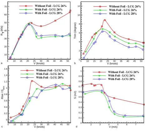
5. 3. Results in Ballast Load Figure 6 indicates the result of the hydrofoil test in ballast load condition for maximum velocity. Regarding to the figure, boat draft decreased when the hydrofoil installed and area where spray is composited, pulled to the corner. Furthermore, hull tunnel exits from water completely in hydrofoil boat unlike the without hydrofoil one (that was on water surface). Figure 7 shows the results of the
tests with and without foils for the ballast load condition. It can be seen that at speed below 20 knots, the resistance, trim and rise of the boat both, with and without foils, are very similar, and the foil system does not have wrecking effect at low speed performance. Above 20 knots, the foils help the boat to get onto the plane mode faster and water clears from the tunnel. The hydrofoils also reduce the running trim by 2 degrees at the hump, down to more favorable values.
This will improve the hump transverse stability of the boat. Once the boat is on the plane, the wetted area of the boat, compared to the hull without foils, is substantially reduced. This results in a large reduction in friction resistance and the large reduction in overall resistance. At 52 knots the hydrofoils reduce the total resistance about 50%. Tests for the different LCGs show very little difference in resistance and only a small change in trim. Therefore, the boat is not sensitive to LCG shift, which is a favorable condition.
With Hydrofoil LCG 26% With Hydrofoil LCG 28%
Without Hydrofoil LCG 28%
Figure 6. Test with and without foil at high speed
V (knots)
R
(K
N
)
5 10 15 20 25 30 35 40 45 50
10 20 30 40 50 60
70 Without Foil - LCG 26%
With Foil - LCG 26% With Foil - LCG 28%
T
a V (knots)
T
ri
m
(d
e
g
re
e
)
5 10 15 20 25 30 35 40 45 50
0 2 4 6 8 10
12 Without Foil - LCG 26%
With Foil - LCG 26% With Foil - LCG 28%
b
V (knots)
R
is
e
/
D
5 10 15 20 25 30 35 40 45 50
0 0.2 0.4 0.6 0.8 1 1.2 1.4 1.6
Without Foil - LCG 26% With Foil - LCG 26% With Foil - LCG 28%
M
A
X
c V (m/s)
S
(m
2
)
2 3 4 5 6 7
0 0.1 0.2 0.3 0.4 0.5 0.6 0.7 0.8 0.9
1 Without Foil - LCG 26%
With Foil - LCG 26% With Foil - LCG 28%
d
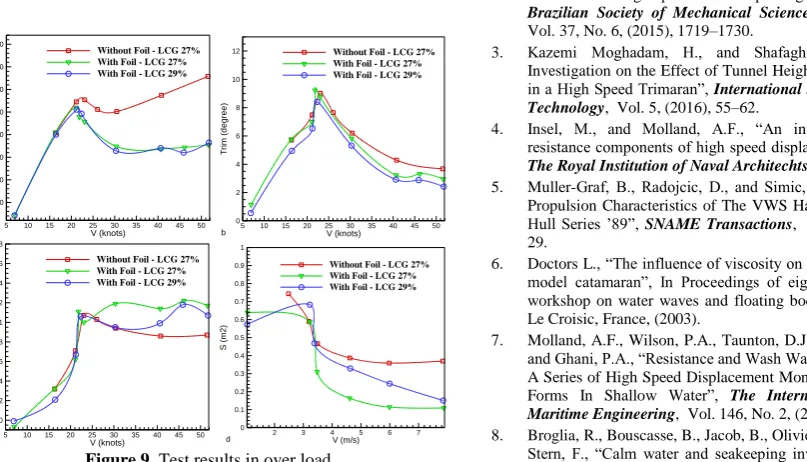
5. 4. Results in Over Load Consequences of the model test in over load and at high speed are shown in Figure 8. In this weight hydrofoil boat expose better function than main boat. As for the figure, wetted surface of hydrofoil boat become very lower and the area of spray compound establish in behind greatly.
Figure 9 shows the results of the tests with and without foils for the over load condition. The foils again show improvements in performance from about 20 knots and higher speeds although, unlike the ballast load condition, the foils do not help to reduce the hump trim in this condition, for the over load condition. This is because they have not been designed to operate optimally for this load condition. At speeds of 52 knots, the resistance reduction is almost 50%. Partially less resistance reductions are achieved as the LCG for the over load condition is farther forward and thus the load distribution between the foils is not ideal. The performance in this condition could be improved farther if the hydrofoils are redesigned for this load condition.
With Hydrofoil LCG 27% With Hydrofoil LCG 29%
Without Hydrofoil LCG 29%
Figure 8. Test with and without foil at high speed
V (knots)
R
(K
N
)
5 10 15 20 25 30 35 40 45 50
10 20 30 40 50 60 70 80
Without Foil - LCG 27% With Foil - LCG 27% With Foil - LCG 29%
T
a V (knots)
T
ri
m
(d
e
g
re
e
)
5 10 15 20 25 30 35 40 45 50
0 2 4 6 8 10
12 Without Foil - LCG 27%
With Foil - LCG 27% With Foil - LCG 29%
b
V (knots)
R
is
e
/
D
5 10 15 20 25 30 35 40 45 50
0 0.2 0.4 0.6 0.8 1 1.2 1.4 1.6 1.8
Without Foil - LCG 27% With Foil - LCG 27% With Foil - LCG 29%
M
A
X
c V (m/s)
S
(m
2
)
2 3 4 5 6 7
0 0.1 0.2 0.3 0.4 0.5 0.6 0.7 0.8 0.9 1
Without Foil - LCG 27% With Foil - LCG 27% With Foil - LCG 29%
d
Figure 9. Test results in over load
6. CONCLUSION
In this study the hydrofoil system for a high speed catamaran designed and it was examined in towing tank with scale ratio 1 to 11.43. The model in the varied three states of loading conditions and two centers of gravity for each weight was investigated. These tests were done with and without hydrofoils. In total 9 complete test series were completed. Foil system in over load is designed and it was investigated in different conditions, in order to verify operation of system in different load and sensitivity associated to center of gravity shift. According to results, the hydrofoil boat function at speed below 20 knot is similar to main one. For speeds higher than 20 knot foil assist boat to reach plane mode quickly and observations showed that the water clears from the tunnel. Also, hydrofoil reduces hump trim about 2 degree and thus it increases the stability of the boat. Besides, drag has diminished in high speed by 50% in over load. Likewise, it meets 40% in partial load. By shifting the LCG forward, the hump trim and resistance reduces in more than 40 knots. In this case the position of center of gravity in front is more sufficient. In over load, using foils diminishes drag for speeds above 20 knots. The maximum of trim has not been decreased in ballast load compared to the over load. Furthermore, the resistance has declined about 50% at speed 52 knots.
7. REFERENCES
1. Hoppe, K.-G.W., “Catamaran with hydrofoils”, (1983). https://patents.google.com/patent/US4606291A/en.
2. Kazemi Moghadam, H., Shafaghat, R., and Yousefi, R., “Numerical investigation of the tunnel aperture on drag reduction in a high-speed tunneled planing hull”, Journal of the
Brazilian Society of Mechanical Sciences and Engineering,
Vol. 37, No. 6, (2015), 1719–1730.
3. Kazemi Moghadam, H., and Shafaghat, R., “Numerical Investigation on the Effect of Tunnel Height on Drag Reduction in a High Speed Trimaran”, International Journal of Maritime
Technology, Vol. 5, (2016), 55–62.
4. Insel, M., and Molland, A.F., “An investigation into the resistance components of high speed displacement catamarans”,
The Royal Institution of Naval Architechts, (1992), 1–20.
5. Muller-Graf, B., Radojcic, D., and Simic, A., “Resistance and Propulsion Characteristics of The VWS Hard Chine Catamaran Hull Series ’89”, SNAME Transactions, Vol. 110, (2002), 1– 29.
6. Doctors L., “The influence of viscosity on the wavemaking of a model catamaran”, In Proceedings of eighteenth international workshop on water waves and floating bodies (18 IWWWFB), Le Croisic, France, (2003).
7. Molland, A.F., Wilson, P.A., Taunton, D.J., Chandraprabha, S., and Ghani, P.A., “Resistance and Wash Wave Measurements On A Series of High Speed Displacement Monohull and Catamaran Forms In Shallow Water”, The International Journal of
Maritime Engineering, Vol. 146, No. 2, (2004), 19–38.
catamaran”, In 11th International Conference on Fast Sea Transportation (FAST2011), Honolulu, Hawaii, USA, (2011). 9. Kornew, N., Migeotte, G., Hoppe, K.G., and Nesterova, A.,
“Design of Hydrofoil Assisted Catamarans using a Non-Linear Vortex Lattice Method”, In Second International Euro Conference on High–Performance Marine Vehicles HIPER, Hamburg, Germany, (2001), 306–321.
10. Kandasamy, M., Peri, D., Ooi, S.K., Carrica, P., Stern, F., Campana, E.F., Osborne, P., Cote, J., Macdonald, N., and de Waal, N., “Multi-fidelity optimization of a high-speed foil-assisted semi-planing catamaran for low wake”, Journal of
Marine Science and Technology, Vol. 16, No. 2, (2011), 143–
156.
11. Saha, G.K., Suzuki, K., and Kai, H., “Hydrodynamic optimization of a catamaran hull with large bow and stern bulbs installed on the center plane of the catamaran”, Journal of Marine Science and Technology, Vol. 10, No. 1, (2005), 32– 40.
12. Bouscasse, B., Broglia, R., and Stern, F., “Experimental investigation of a fast catamaran in head waves”, Ocean
Engineering, Vol. 72, (2013), 318–330.
13. Sayyaadi, H., and Nematollahi, M., “Determination of optimum injection flow rate to achieve maximum micro bubble drag reduction in ships; an experimental approach”, Scientia Iranica,
Transactions B: Mechanical Engineering, Vol. 20, No. 3,
(2013), 535–541.
14. Ebrahimi, A., Rad, M., and Hajilouy, A., “Experimental and numerical studies on resistance of a catamaran vessel with non-parallel demihulls”, Scientia Iranica, Transactions B:
Mechanical Engineering, Vol. 21, No. 3, (2014), 600–608.
15. Bakhtiari, M., Veysi, S., and Ghassemi, H., “Numerical Modeling of the Stepped Planing Hull in Calm Water”, International Journal of Engineering - Transactions B:
Applications, Vol. 29, No. 2, (2016), 236–245.
16. Ahmadzadehtalatapeh, M., and Mousavi, M., “A Review on the Drag Reduction Methods of the Ship Hulls for Improving the Hydrodynamic Performance”, International Journal of
Maritime Technology, Vol. 4, (2015), 51–64.
17. Migoette, G., and Hoppe, K.G., “Development in Hydrofoil Assistance for Semi-Displacement Catamarans”, In Fifth International Conference on Fast Sea Transportation, Seattle, Washington, USA, (1999), 631–642.
18. Milandri, G.S., “Seakeeping control of HYSUCATs”, Doctoral dissertation,University of Stellenbosch, (2006).
19. Grobler, B., “Development of a high speed planing trimaran with hydrofoil support”, Doctoral dissertation, University of Stellenbosch, (2007).
20. Sahoo, P.K., Mason, S., and Tuite, A., Practical evaluation of resistance of high-speed catamaran hull forms—Part II, Vol. 3, No. 3, (2008), 239-245.
21. Kopke, M., “A passive suspension system for a hydrofoil supported catamaran”, Doctoral dissertation, University of Stellenbosch, (2008).
22. Homma, N., and Frouws, J.W., “Airfoil Assisted Catamarans: The price of lift is drag”, Ships and Offshore Structures, Vol. 2, No. 2, (2007), 157–168.
23. Swidan, A., Thomas, G., Penesis, I., Ranmuthugala, D., Amin, W., Allen, T., and Battley, M., “Wetdeck slamming loads on a developed catamaran hullform – experimental investigation”, Ships and Offshore Structures, Vol. 12, No. 5, (2017), 653– 661.
24. Hajiabadi, A., Shafaghat, R., and Kazemi Moghadam, H., “A study into the effect of loading conditions on the resistance of asymmetric high-speed catamaran based on experimental tests”,
Alexandria Engineering Journal, Vol. 57, No. 3, (2018),
1713–1720.
25. Kirkman, K., and Kloetzli, J., “Scaling Problems of Model Appendages”, In 19th American Towing Tank Conference, Ann Arbor, Michigan, (1981).
26. ITTC. Recommended Procedures and Guidelines, Revision 02, 26th ITTC Specialist Committee on CFD in Marine Hydrodynamics.
Foil Application to Reduce Resistance of Catamaran under High Speeds and
Different Operating Conditions
H. Kazemi moghadam, R. Shafaghat, A. Hajiabadi
Sea Based Energy Research Group, Babol Noshirvani University of Technology, Babol, Iran
P A P E R I N F O
Paper history: Received 11 June 2018
Received in revised form 19 November 2018 Accepted 03 January 2019
Keywords: Catamaran Hydrofoil Load Conditions Towing Tank Drag Reduction هدیکچ ،هزورما زاین هب تعرس لااب و زین تیلباق لمح راب رتشیب نیققحم ار هب تمس هدافتسا زا یاهروانش یبیکرت قوس هداد تسا . روانش تکوسیاه یکی زا عاونا یاهروانش یبیکرت تسا هک اب بیکرت روانش ناراماتاک و لیوفوردیه یحارط هدش تسا . یاهروانش نراماتاک هب ناونع یعون زا یاهروانش دنچ ،هندب هب رطاخ نیمات نامزمه تعرس لااب و یرادیاپ ،بسانم هراومه دروم هجوت ناحارط و ناربراک یاهروانش وردنت هدوب دنا . نیا اهروانش اب دوجو حطس هدشرت رتشیب گرد یرتلااب زین دنراد هک اب ب یریگراک لیوفوردیه حطس هدشرت روانش رتمک هدش ببس شهاک گرد روانش یم دوش . یحارط متسیس لیوفوردیه اب هجوت هب نزو و زکرم مرج روانش تروص یم دریگ . رد نیا هعلاطم هب یسررب هدافتسا زا لیوفوردیه رد کی روانش ناراماتاک وردنت رد طیارش راب و زکرم مرج توافتم هتخادرپ هدش تسا . لدم رد هس تلاح یراذگراب نوگانوگ ( راب ،کبس راب لماک و راب نیگنس ) و ود زکرم مرج یارب ره نزو یسررب هدش تسا . نیدب روظنم 9 یرس لماک تست رد هچضوح ششک رب یور روانش لدم اب سایقم 1 هب 34 / 11 تروص تفرگ و رد تیاهن جیاتن یارب روانش یلصا اب هدافتسا زا لدم دورف و ITTC هئارا دش . اب هجوت هب جیاتن ،تست دافتسا ه زا متسیس لیوفوردیه اب ثع شهاک گرد ات 05 % یم دوش . رد تلاح راب کبس زکرم مرج رتولج و رد تلاح راب نیگنس زکرم مرج بقع رت بولطم تسا .