INTRODUCTION
The dynamic development of machines, tool materials and tool design solutions enabled mill-ing to be the last operation performed in the prod-uct forming process, even for the materials after heat treatment. The numerically controlled ma-chines enable automation of the manufacturing processes. Much attention is paid to optimise the machining in a way that should result in obtaining the best possible surface quality and increasing the efficiency, which reduces the machining time. This is related to the selection of appropriate machining strategy. The most popular are such machining methods as: HSC associated with the finishing operations, and HPC intended to maxi -mise the material removal rate. The CAM system manufacturers offer various types of machining strategies tailored to the machining methods. In the case of HPC machining, the general assump -tions cover minimisation of idle movements,
maximum use of the tool working point, smooth -ing of the machin-ing paths, etc. High efficiency of machining is especially required in the case of the thin-wall components used in the aviation indus-try, when sometimes a finished part constitutes less than 10% of the initial semi-product volume.
The authors of this study [1] analysed the im-pact of the machining strategy on the accuracy of dimensions and shape as well as the surface roughness while milling the thin walls made of Ti6AI4V titanium alloy. When machining a 1 mm-thick wall, four different machining strate -gies were tested. It was observed that while ap-plying the strategy that consisted in machining of the wall in two passes (one per each side of the wall), vibration occurred, which resulted in a significant increase of roughness in the upper part of the wall (on the area being most distant from the fastening). On the other hand, the op-timal approach as regards obtaining the highest dimensional accuracy was the alternate strategy
Highly Efficient Milling on the Example
of Selected Machining Strategies
Kazimierz Zaleski
1, Jakub Matuszak
1*, Andrzej Zyśko
11 Lublin University of Technology, Faculty of Mechanical Engineering, ul. Nadbystrzycka 36, 20-618 Lublin, Poland
* Corresponding author’s e-mail: [email protected]
ABSTRACT
The pursuit to achieve a broadly defined optimisation of the manufacturing processes imposes the use of the in
-creasingly innovative machining methods. The increase of the machining efficiency, assuring a high surface qual -ity as well as precision of dimensions and shapes, necessitates the search for new methods to meet the demanding
requirements, apart from the development of materials used for the working parts of tools, wear-resistant coatings
or improvement of the cutting tool point geometry. One of the methods to improve forming by machining is the
optimisation of the machining strategy during the manufacture of the components having complex shapes. The progress in this field is particularly noticeable along with development of the software for machining on multi-axis
machines. This article presents the results of tests for the impact of machining strategy on passive force, cutting torque, material removal rate, topography of the obtained surface and the shape of chip resulting from the alu-minium alloy milling. The tests were performed by comparison of the classic strategy available in the NXCAM system to the iMachining technology.
Keywords: passive force, cutting torque, iMachining, milling strategy.
Volume 14, Issue 1, March 2020, pages 167–177 https://doi.org/10.12913/22998624/116356
Research Journal
Accepted: 2020.02.05with the smallest machining depth ap = 3 mm used during the experiment. However, this strategy re -sulted in the smallest volume efficiency.
The article [2] includes the analysis of the impact of down milling and up milling on the surface roughness (Rz parameter) of a 10 mm-thick wall made of C45 steel. The mathematical model was elaborated to consider the engineer-ing parameters of millengineer-ing that proved to be highly compliant with the measurement results. On the basis of the simulation and the experiment, it was proven that better surface quality was obtained as a result of down milling.
In the aviation and automotive industry, mill-ing is frequently performed on free surfaces. In order to obtain a good quality of surfaces, the ma-chining paths of the ball-shaped cutter must be concentrated. The study [3] includes the analysis pertaining to the impact of the ball-shaped cutter angle in relation to the machined surfaces of thin walls on the accuracy of dimensions and shape. The angles of 15, 20, 30, 40 and 45 degrees were selected for the tests. It was proven, both by FEM simulation (Finite Element Method) and during the test experiment that the least strain of a 2 mm-thick wall was obtained when applying the angles of 15 and 45 degrees. In the study [4], the new milling strategy for free surfaces was
proposed to increase the cutting edge dura-bility while milling the hard-to-machine nickel-based alloy (GH4169). Such a strategy consists in the active control of the ball-shaped cutter work -ing part involvement. The concept anticipated that the ball-shaped part of the cutter would split into segments and the angle of the cutter would change while milling in relation to the workpiece for the purpose of full use of the working part. This allowed to increase the tool durability. The problem with the tool wear is also mentioned in the study [5], in which the authors investigated the impact of the microstructure of cutters made of sintered carbides on the durability while mill-ing the titanium-based Ti6Al4V alloy. It was proven that the tools having the ultra-fine-grained structure show the highest durability, especially crash wear resistance.
The problem with choosing the optimum strategy for milling a pocket is discussed in the study [6]. The impact of such factors as cutting speed, feed per tooth, cutting depth and width on the machine effects was analysed as well. The pa -rameters were optimised and chosen on the basis of the Taguchi method. The spiral strategy proved
to be the best one out of the three strategies for milling a pocket.
The analysis of the machining strategies dur-ing HSM (high speed milldur-ing) of forms and dies is discussed in the publications [7, 8]. The shape complexity of the elements of this type requires appropriate machining strategies. It was found that the manufacturing process by the HSM meth-od should be analysed upon dividing the machin-ing into the followmachin-ing stages: rough machinmachin-ing, semi-finishing and finishing. The issue of optimi -zation as regards obtaining the best quality and the milling cutter durability should cover such aspects as: shape, size and local curvature of the workpiece, geometry of the milling cutter and en -gineering parameters of machining.
Machining of rotors or skew gears is one of most complicated machining processes [9]. It usually requires 5-axis machines and optimisa -tion of tool paths. The issues related to search-ing for the tools with the possibly largest di-ameter for machining the rotors to increase the machining efficiency are analysed in the publi -cation [10]. In turn, the concept of searching for the optimum strategy for rotor machining based on minimum machining force is analysed in the publication [11].
A popular method of slot milling is trochoidal milling. This method assumes the use of larger axial milling depths ap and smaller milling widths ae. This gives many advantages, such as: better use of the working part, smaller values of forces in the radius direction. The authors of the publi-cation [12] analysed the impact of the trochoid step on such indicators as machining force and vibration amplitude. The milling speed and the trochoid lead were proven to have a significant impact on the machining effects.
The element surface quality after milling is one of the key factors. Many authors were rais -ing the problem of machin-ing strategy optimisa-tion as regards the surface quality improvement [13, 14, 15, 16, 17, 18, 19].
In this article, an attempt was made to com-pare the conventional strategy to the iMachining strategy as regards process efficiency, chip shape, surface roughness, passive force and cutting torque.
METHODOLOGY
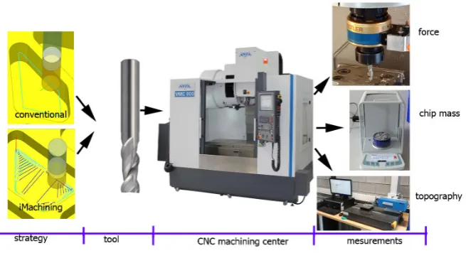
Milling was performed on the Avia VMC800HS vertical machining centre with the Heidenhain iTNC 530 control system hav-ing the maximum rotational speed of spindle n=24000 rpm and maximum plane motion speed of 40 m/min.
The workpiece was a 220 x 170 x 65 mm spec -imen of EN AW 7075 T651aluminium alloy. The tests were conducted using the FRAISA 10 mm-dia. double-bit flycutter (symbol C15520.450)
made of sintered carbides with Celero wear-re-sistant coating. In order to generate the paths of the tool machining strategy chosen, the Siemens NX 10 software with the iMachining overlay of SolidCam make was applied. Fig. 1 shows the test stand lay-out.
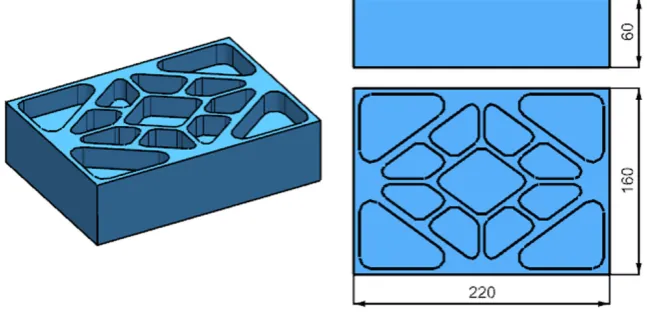
The changing factors during milling were: the type of applied machining strategy and the machining parameters that were adjusted to dif-ferent values of machining depth ap and width ae being characteristic for the chosen machining strategy. The model of a part on which the above-mentioned engineering tests were conducted is presented in Fig. 2.
The first experiment was performed using the standard strategy. The manufacturer-recommend-ed parameters were applimanufacturer-recommend-ed, i.e. n = 12000 rpm, vf = 2000 mm/min. The machining depth for a single path was established for the constant level
Fig. 2. Model of a part used for the test
of 2 mm. The parameters were adjusted to the technical capabilities of the machine and the ap-plied tool.
The second experiment was conducted on the same semi-product using the iMachining strategy. In accordance with the characteristics of this strat-egy, the machining depth of 20 mm was applied to make use of the entire cutting edge length. The technology of the applied strategy enables to au-tomatically select the rotational speed of the spin-dle and its rate of feed owing to the automatic cut-ting parameter selection creator. Any change of such parameters is possible through the so-called machining intensity level, the value of which is from 1 to 8. As the rate of feed is changing at the time of machining and its value is adjusted to the geometry being currently machined, only the in-put parameters of the tool can be determined, i.e. n = 12000 rpm, vf = 2000 mm/min. The default and recommended level of machining intensity is 3. However, after the machine rigidity analysis and the initial testing performance, the machining intensity level was established to be 6.
The whole experiment was carried out using a cutting fluid.
The passive force and the cutting torque were measured using the Kistler 9125A rotary force gauge (Winterthur, Switzerland). In the measure-ment path, the force gauge was combined with the 5237A1/A2 actuator and the DAQ 5697A data acquisition block.
The weight loss was determined using the an-alytical balance having the accuracy of 0.01 mg.
The surface topography was analysed on the T8000RC120-400 profilographometer provided
by Hommel–Etamic. The roughness was mea-sured on the pocket bottom, upon previous re -moval of the wall to enable access of the gauging point of the head. The schematic diagram of the experiment is shown in Figure 3.
The following factors were compared during the tests: machining time of workpiece pocket, lay patterns, surface roughness, form and shape of chips, factor of volume occupied by chips, passive force and cutting torque at the time of machining.
RESULTS
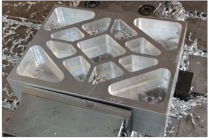
Figure 4 presents the view of an element made in accordance with the iMachining strategy. The pocket-type structures in which a significant portion of material is removed while machining is characteristic for the aviation industry.
In order to compare the machining effects, the objects having the same geometry were made us-ing the conventional strategy, the same machine, tool and technological tooling.
Impact of technology on machining time and material removal rate MRR
By analysing the machining times for par-ticular strategies that amounted to 20.52 min-utes for the standard strategy and 11.12 min for the iMachining strategy, it can be stated that the time saved, in case of the example above, is approx. 85%.
Impact of technology on the surface quality
A significant parameter that determines the part manufacture is the surface quality, and name-ly its roughness that is determined by such pa-rameters as: Ra, Rz. In the experiment, the rough machining was applied, after which the finishing process often takes place and despite this, for a significant quantity of part, this is most often the final machining and the resultant surface quality remains on the final product. In the conducted ex -periment, both machining strategies resulted in a similar surface condition, although iMachining took significantly less time (Fig. 6). This allows to state that the machining can be performed in a more effective manner without significantly im -pairing the roughness parameters.
Figure 7 shows the surface topography af-ter the applied machining methods. For the iMachining strategy, not only the signs of the cut-ting edge feed were visible but also the signs of subsequent tool passes on the specimen face. In turn, in the case of the conventional machining, the signs of subsequent application of the cutting edge (reflection of the cutting edge feed) were visible. Upon analysing the surface parameters, it was found that smaller roughness was obtained after iMachining (parameters: Sa and Sz).
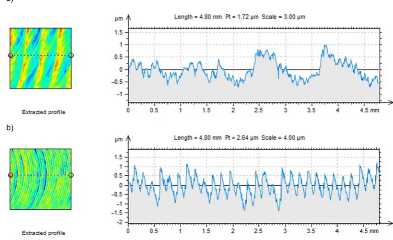
Figure 8 presents the view of surface rough-ness profile for the applied strategies. There are signs of subsequent tool passes visible in the case of the iMachining strategy.
Fig. 5. Comparison of material removal rate MRR
Fig. 8. View of roughness profile after machining: a) iMachining strategy, b) conventional strategy
Fig. 7. View of surface topography after machining: a) iMachining strategy, b) conventional strategy
Impact of technology on the chip shape and form
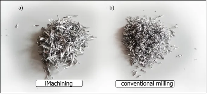
Figure 9a presents the exemplary shapes of chips resulting from machining the EN AW 7075 T651 aluminium alloy that is milled by means of Fraisa tools with the iMachining method. There is a significant difference between the shape of such chips and the form of chips presented in Figure 9b that resulted from conventional technology ma-chining. The chips originating from iMachining have a more repeatable shape and are more twist-ed. In turn, the chips after conventional machin-ing have the reduced dimensions. The chip shape depends on many different factors, such as: ge -ometry of the applied cutting tools, type of the material machined, technological conditions of machining.
For the chips that originated while machin-ing per two strategies, the chip volume factor kch
was determined, expressed as the ratio of volume occupied by chips Vch to the volume of the same weight of solid material Vm:
k
"#=
V
V
"# &Figure 10 shows the values of the determined factor. The factor was 16.5 for the conventional machining and 35.4 for the iMachining, which weights in favour of the conventional machining as regards the intensity of filling the collective containers with chips in the production plant.
Due to high efficiency and intensity of HSC and HSM machining, the shape and form of chips is highly important for their quick evacu -ation from the machining zone. This is very crucial for the machining process performance safety and the applied tool durability. When milling the closed pocket structures, there is a
Fig. 10. Comparison of the chip volume factor values
risk that chips will be trapped in the pockets and their removal will be rendered difficult. A great -er value of the factor of volume occupied by the chips makes the chip removal from the machin -ing zone, especially from the closed pockets, by means of liquids or gases, more efficient in the case of iMachining.
Impact of technology on the machining force and torque
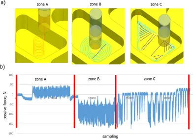
Certain characteristic zones can be distin-guished when machining the pockets in ac -cordance with the iMachining strategy. The tool paths for particular zones are presented in Figure 11a, while the corresponding passive force runs are shown in Figure 11b. Zone A is the zone of tool penetration to the full machin-ing depth (ap = 20). The characteristic feature of this zone are the positive values of passive force. Zone B is the zone of static load of the tool, which is one of the main assumptions of the iMachining strategy. Due to the fact that machining in this zone is performed with the main cylindrical part of the milling cutter the cutting edges of which are distributed along the screw line, the resultant passive force takes the
negative values. Zone C is for machining the corners. In this zone, the tool contact with the workpiece is interrupted, which is visible in the passive force run (visible moments of passive force return to the 0 value).
Three characteristic zones can also be ob-served for the machining performed by con-ventional strategy (Fig. 12). In zone A, the tool penetrates the material to the screw line. The characteristic feature of this zone are the posi-tive values of passive force. In zone B, the tool starts machining at the depth of ap = 2 mm, but there are sections in this zone in which the tool paths overlap, which results in the passive force return to zero. In zone C, the machining at con-stant value of machining width ae, and thus the constant force run within the entire zone can be observed.
The machining of the entire pocket required removal of material at 10 levels for the assumed machining depth ap = 2 mm and the pocket depth of 20 mm. The passive force run for 3 exemplary levels is presented in Figure 13.
By comparing the absolute values of passive force for two strategies applied, it can be noticed that the conventional machining has lower values of passive force.
Fig. 11. Passive force run during different stages of machining with use of iMachining strategy:
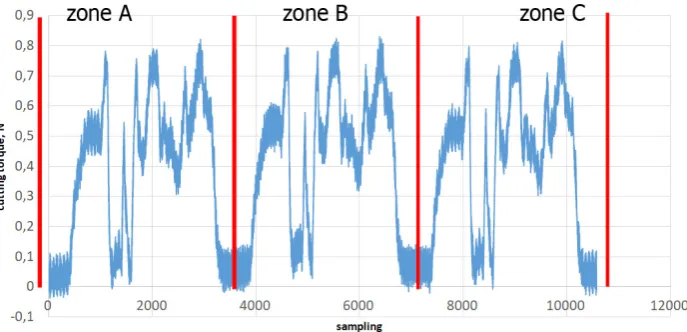
Figures 14 and 15 show the cutting torque run respectively for the iMachining strategy (Fig. 14) and the conventional strategy (Fig. 15). The high-est values of cutting torque for the iMachining strategy (approx. 1.6 Nm) are observed in the zone B, in which the working part is involved most.
For the conventional strategy, for each ma-chining level, the torque run assumes a similar nature. The maximum transient value of cutting torque is approx. 0.8 Nm.
CONCLUSIONS
In this article, two machining strategies ap-plied for the HSM process while milling the EN-AW 70705 aluminium alloy were analysed. On the basis of the conducted experimental tests, the following conclusions can be drawn:
• A better use of the working part of a cutting tool while machining by iMachining strategy allows increasing the machining efficiency Fig. 13. Passive force run while milling at 3 machining levels
Fig. 12. Passive force run while machining of one level by conventional strategy:
volume by approx. 85% as compared to the conventional machining.
• A slightly lower values of roughness param-eters (Sa and Sz) were obtained for the ma-chining performed in acc. with the iMama-chining strategy.
• During the conventional machining, the ob-tained values of chip volume factor kch were halved, which allows to better use the collec-tive containers in the production plant.
• A low value of factor kch may cause problems with evacuation of chips from the machining zone during the HSM process, especially dur-ing the pocket structure machindur-ing.
• The values of passive force and cutting torque are lower in the case of the conventional machining.
• Upon analysing the force and cutting torque run when machining a closed pocket, it is pos -sible to distinguish three characteristic stages of machining: tool penetration to the full ma-chining depth, mama-chining with constant tool load and machining of corners.
Acknowledgements
The project/research was financed under the project Lublin University of Technology-Region-al Excellence Initiative, funded by the Polish Ministry of Science and Higher Education (con-tract No. 030/RID/2018/19).
REFERENCES
1. Kuczmaszewski, J., Zaleski, K., Matuszak, J., & Mądry, J. (2019). Testing Geometric Precision and
Surface Roughness of Titanium Alloy Thin-Walled
Elements Processed with Milling. In Advances in
Manufacturing II (pp. 95-106). Springer, Cham. 2. Michalik, P., Zajac, J., Hatala, M., Mital, D., & Fe
-cova, V. (2014). Monitoring surface roughness of thin-walled components from steel C45 machining down and up milling. Measurement, 58, 416-428. 3. Shan, C., Lv, X., & Duan, W. (2016). Effect of tool
inclination angle on the elastic deformation of
thin-walled parts in multi-axis ball-end milling. Procedia CIRP, 56, 311-315.
Fig. 14. Cutting torque while machining in acc. with iMachining strategy in particular zones
4. Luo, M., Luo, H., Zhang, D., & Tang, K. (2018). Improving tool life in multi-axis milling of Ni-based
superalloy with ball-end cutter based on the active
cutting edge shift strategy. Journal of Materials Pro -cessing Technology, 252, 105-115.
5. Kuczmaszewski, J., Zaleski, K., Matuszak, J., Pałka, T., & Mądry, J. (2017). Studies on the ef -fect of mill microstructure upon tool life during
slot milling of Ti6Al4V alloy parts. Eksploatacja i Niezawodność, Maintenance and Reliability, vol.
19, no. 4, 590–596.
6. Gologlu, C., & Sakarya, N. (2008). The effects
of cutter path strategies on surface roughness of
pocket milling of 1.2738 steel based on Taguchi
method. Journal of materials processing technol-ogy, 206(1-3), 7-15.
7. Toh, C. K. (2005). Design, evaluation and optimisa-tion of cutter path strategies when high speed ma-chining hardened mould and die materials.
Materi-als & design, 26(6), 517-533.
8. Toh, C. K. (2006). Cutter path strategies in high
speed rough milling of hardened steel. Materials &
design, 27(2), 107-114.
9. Álvarez, Á., Calleja, A., Ortega, N., & de Lacalle, L. (2018). Five-axis milling of large spiral bevel gears: toolpath definition, finishing, and shape er -rors. Metals, 8(5), 353.
10. Baohai, W. U., Ming, L. U. O., ZHANG, D., & Fei -yan, H. A. N. (2019). An automated approach to
cal-culating the maximum diameters of multiple cutters
and their paths for sectional milling of centrifugal
impellers on a 4½-axis CNC machine. Chinese Jour -nal of Aeronautics, 32(4), 1030-1039.
11. Calleja, A., Alonso, M. A., Fernández, A.,
Taber-nero, I., Ayesta, I., Lamikiz, A., & López de La
-calle, L. N. (2015). Flank milling model for tool path programming of turbine blisks and compressors. In
-ternational Journal of Production Research, 53(11),
3354-3369.
12. Zagórski, I., Kulisz, M., Kłonica, M., & Matuszak,
J. (2019). Trochoidal Milling and Neural
Net-works Simulation of Magnesium Alloys. Materi -als, 12(13), 2070.
13. Bawono, B., Anggoro, P. W., Bayuseno, A. P., Ja
-mari, J., & Tauviqirrahman, M. (2019). Milling
strategy optimized for orthotics insole to enhance surface roughness and machining time by Taguchi and response surface methodology. Journal of
Indus-trial and Production Engineering, 36(4), 237-247.
14. Wibowo, Y. T., Baskoro, S. Y., & Manurung, V.
A. (2018, February). Toolpath Strategy and
Opti-mum Combination of Machining Parameter during Pocket Mill Process of Plastic Mold Steels Mate
-rial. In IOP Conference Series: Materials Science and Engineering (Vol. 306, No. 1, p. 012137). IOP Publishing.
15. Etyemez, A. (2016). Optimization of Effects of Pocket Tool Path Strategies and Cutting
16. Zaujec, R., Vopát, T., Šimna, V., & Pokorný, P. (2017). The influence of cam strategies on the tool wear and surface roughness. Annals of DAAAM & Proceedings, 28.
17. Logins, A., & Torims, T. (2015). The influence
of high-speed milling strategies on 3D surface
roughness parameters. Procedia Engineering, 100,
1253-1261.
18. Zagórski, I., & Korpysa, J. (2019). Surface Quality
in Milling of AZ91D Magnesium Alloy. Advances in Science and Technology. Research Journal, 13(2), 119-129.
19. Krolczyk, G., Legutko, S., & Gajek, M. (2013). Pre -dicting the surface roughness in the dry machining
of duplex stainless steel (DSS). Metalurgija, 52(2),
259-262.
20. Fulemova, J., Hnatik, J., Kozmin, P., Sklenicka, J. Influence of cooling methods on tool life dur -ing machin-ing with iMACHINING strategy