MODELLING AND EXPERIMENTAL VALIDATION OF COMBUSTION
IN STRAIGHT INOCULATION COMPRESSION IGNITION ENGINE
FUELLED WITH DIESEL AND JATROPHA METHYL ESTER BLEND
Biswajit De
*, Rajsekhar Panua
Mechanical Engineering Department, National Institute of Technology, Agartala, Tripura, 799055, India
ABSTRACT
An incorporated arithmetical model has been urbanized and investigated for CFD replication of a solitary cylinder, four stroke, straight inoculation, compressed ignition diesel engine of 3.5 kW for in-cylinder combustion analysis and authenticated under engine simulations at full load functioning conditions with foundation fuel diesel and 10% JME (volume basis) blend with diesel at invariable speed of 1500 rpm. For advancing the exactness of the exertion, a number of sub models, such as species transport model explaining the actual biodiesel energy content and molecular structure as soon as fuel blend is initiated, spray break-up model, wave model and pre-mixed combustion model are also initiated. Consequences of replication and the data from corresponding experimental investigation are evaluated to one another in terms of pressure traces, heat release rates. Excellent concurrences of pressure trace, heat release rate is accomplished involving the experimental and predicted data for all the tested fuels. The outcomes demonstrate that the anticipated mechanism offers reliable predictions of in-cylinder combustion.
Keywords: CFD; k-ε model; simulation; validation;
*Corresponding Author. Email: [email protected]
1.
INTRODUCTION
In current years, CFD modeling is an effective tool for the analysis of diesel engine combustion and emissions in preference to full experimental study. The main advantages of CFD simulations are that it gives details on spatial and temporal variations of local in-cylinder properties and also saves time, cost and manpower (Andreadis et al. and O’Rourke et al.). Goldsworthy et al. (2006) in his study considered a simplified evaporation and combustion model, fuelled with Heavy fuel oil (HFO), as a mixture of a heavy (residual) and a light (cutter) component, implemented in CFD code Star-CD. During the experiments, it was found that gauged and computed data for ignition delay, burning rate, spray and flame structure were closer to each other. Struckmeier et al. (2009) deliberated an additional comprehensive approach of HFO modeling with a KIVA-based code, supplementary embryonic evaporation, ignition and combustion models and originated that a excellent conformity between the simulated data and the experimental data. Kyriakides et al. (2009) urbanized a comprehensive model of heavy fuel oil (HFO) with the fuel properties belongings to thermo physical properties, together with viscosity, surface tension, vapour pressure, enthalpy and latent heat of evaporation versus temperature. The model was experienced in an invariable volume combustion chamber through replications of non-evaporating and evaporating sprays. Herrmann et al. (2009, 2010) represented the diesel fuel spray experimental results of a large marine Diesel engine by modeling a bulky unvarying volume combustion chamber for presenting the measurements concerning the spray break up and combustion with modification of the swirl concentration, the air temperature and pressure inside the chamber, as well as the injector features (number of holes, orifice diameter and spray orientation). Garaniya et al. (2011) studies a comprehensive model of heavy fuel oil
(HFO) by making an allowance for the consequences of the high molecular weight hydrocarbons in HFO with the intention of including the tendency to undergo thermal cracking and polymerization. The intention of the present investigation is to authenticate a pre-mixed combustion model in association with the existing dynamic mesh and spray models in conjunction with an experimental data set consisting of diesel and 10% JME (volume basis) blend with diesel at full load functioning circumstances at unvarying speed of 1500 rpm.
2.
NUMERICAL PROCEDURE
2.1
CFD code and calculating meshes
In the present study, CFD package, FLUENT 6.3 software is used for modeling the multifaceted combustion happening in compression ignition engine. The injector is modeled at the midpoint of the combustion chamber for symmetrical location and the CFD computations are executed on 00 sector mesh. Simulation on in-cylinder flow and combustion processes are contemplated by adding exhaust and intake ports in the computational mesh. Computations commence at Intake Valve open and stop at Exhaust Valve closing. The entire computations are utilized the identical initial and boundary conditions. Computations are done by employing the time step of 0.2 deg of crank angle. Exact number of cells in the mesh is 30225 and 35311 at TDC and BDC, respectively.
2.2
Spray Model
The standard WAVE model (Liu et al., 1993) is employed for the primary and secondary atomization modeling of the consequential droplets. This model includes the enlargement of a primary perturbation on a liquid surface which is related to its wave length and to other
Frontiers in Heat and Mass Transfer
physical and dynamic parameters of the injected fuel. In this model the growth of an initial perturbation on a liquid surface is linked to its wave length and to other physical and dynamic parameters of the injected fuel and the domain fluid. Nozzle exit diameter is accountable for the injected drop packages with attribute size. Nozzle exit diameter is accountable for the injected drop packages with attribute size. The treatments of the droplets are prepared by the process of heat-up and evaporation including to the assumption of uniform droplet temperature is described in Dukowicz model. Drop parcels are injected with characteristic size equal to the nozzle exit diameter (blob injection). The Dukowicz model was applied for treating the heat-up and evaporation of the droplets, which is described by Dukowicz et al. (1979). This model assumes a uniform droplet temperature. In addition, the rate of droplet temperature change is determined by the heat balance, which states that the heat convection from the gas to the droplet either heats up the droplet or supplies heat for vaporization. The spray wall interaction model (Naber et al., 1988) assumes that a droplet, which strikes the wall, is pretentious by rebound or reflection, based on the Weber number. The Shell auto-ignition model (Halstead et al., 1977) is employed for modeling the auto-ignition describing the generic mechanism, 6 generic species for hydrocarbon fuel, oxidizer, total radical pool, branching agent, intermediate species and products.
2.3
The Turbulent Mixing Model
The k-ɛ approach has been exploited to take account of turbulent effects, while the multifaceted oxidation progression of diesel fuel has been recapitulated by a single step irreversible reaction (Liu et al., 1993 and ICE Physics & Chemistry, 2009). The mean reaction rate has been assessed through the Coherent Flamelet Model (Colin et al., 2004). Intended for a diesel spray, the fuel dewdrops are extremely close to each other and are situated in a region basically made of fuel. Subsequent to the evaporation of the fuel, a sufficient time is wanted for the mixing from the nearly pure fuel region with the surrounding air.
2.4
The Combustion Model
The combustion model is based on the Coherent Flame Model (ECFM-3Z model) differentiates linking all three main regimes relevant in diesel combustion, namely auto-ignition, premixed flame and non-premixed, i.e. diffusion combustion (Colin et al., 2004 and Hélie et al., 2000). The premixed charge of fuel and air is utilized to compute the auto-ignition pre-reactions combining with the ignition delay presided over the local temperature, pressure, fuel/air equivalence ratio and the quantity of remaining gases. Local auto-ignition is afterward the premixed combustion in the fuel/air/residual gas mixture created during the time period between start of injection and auto-ignition onset within the ECFM-3Z modeled according to a flame propagation progression. The third establishment is the one of diffusion combustion where the reaction takes place in a thin zone which detaches fuel and oxidizer. It is implicit that the time needed for the diffusion process is much greater than that of the chemical time in the reaction zone and the rate of reaction throughout the diffusion combustion is computed completely by the intermixing of fuel and oxidizer. This distinct partition of the several ignition/combustion regimes makes the ECFM-3Z model purposely made to conventional as well as alternative diesel combustion modes. For the most part of combustion process of conventional fuel can be presumed as diffusion type but newly initiated substitute conception is that a large amount of fuel is consumed within the premixed combustion.
2.5
Mesh generation
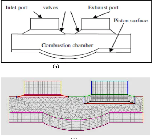
Figure 1(a) illustrates the computational domain of two dimensional combustion chamber geometry of the diesel engine with inlet and exhaust ports and (b) demonstrates the mesh structure of computational domain for model geometry at 605 degree Crank angle.
The mesh organization is detached into two zones; uncomplicated geometry of the indisputable preparation facilitates zones 1 to construct by utilizing the quadrilateral structured mesh. The deformation of the dislodgment volume during compression and expansion strokes and the movements of the inlet and exhaust valve manages zone 2 to acquire the advantage of the triangular structured mesh. The piston and valve movements are arranged specifically by the crank angle based functions. The mesh is composed of approximately 30,225 computational cells when the piston is at the Top-dead centre location, with a resolution of 2 mm.
(a)
(b)
Fig. Model Geometry of combustion chamber with valves 1(a) at
00 Crank angle and (b) Mesh structure of computational domain at 605 degree Crank angle
2.5.1 Gas Exchange Phase
The province for the computation of the gas exchange incorporates the parts of the intake and exhaust channel with something like diameter of 28.2 mm and 28 mm, correspondingly. Initial and boundary circumstances of the computational model are developed from experimental results of engine measurements as well as from two-dimensional engine cycle process simulations using the program code FLUENT 6.3. The channel is represented with quadrilateral cells of h = 4.5 mm size. The size of quadrilateral elements is refined to h = 2 mm, near the valves and to h = 0.11 mm, near the valve seats. On the whole the magnitudes of the computational mesh in the gas exchange phase diverge among 30225 and 33215 thousand elements.
2.5.2 Diesel or JME blend Injection Phase
Making an allowance for the computation of the supersonic diesel or JME blend jet and high velocity gradients at the diesel or JME blend inflow, the resolution of the numerical grid is sophisticated analytically. Diesel or JME blend injection commences at 230 BTDC. A sensitivity testing considering the influence of the grid resolution on computational results shows a sufficient discritization of the proposed mesh.
2.5.2 Compression and Expansion Stroke
overall number of elements within the domain varies between 33215 and 35311 thousand elements depending on the piston lift.
3
SOLUTION PROCEDURE, GRID
INDEPENDENCY TEST AND VALIDATION
3.1
Solution Procedure
3.1.1 Initial and Boundary Conditions
CFD computations considered the gas exchange phase throughout the exhaust and intake stroke, diesel or JME blend injection during the compression stroke and the combustion/ expansion phases. Initial and boundary circumstances of the computational model are developed from experimental results of engine measurements as well as from two-dimensional engine cycle process simulations using the program code FLUENT 6.3. Unsteady pressure and temperature boundary conditions are described at the intake and exhaust port developed from two-dimensional engine cycle simulations. Wall boundary conditions are developed commencing two-dimensional engine cycle simulations utilizing a simple finite volume method with the intention of approximation the mean wall-temperatures of the in-cylinder geometry. Inlet boundary conditions for diesel or JME blend injection are described at the characteristics of the injector. The diesel or JME blend inoculation profile is urbanized by the mass flow inlet boundary condition originated from the injector needle lift measurements and from the values of the averaged mean mass flow. With the supposition of proportionality linking to the needle lift and mass flow, a profile is developed from the start of injection (SOI) and from the end of injection. The measured value of the injected fuel mass is employed to indicate a representative profile which is ultimately used as boundary condition for diesel or JME mass flow rate in the CFD computations. Diesel or JME blend is alleged to be heated up to the level of the coolant temperature within the cylinder head, in view of the fact that the injector is entirely enclosed by the cylinder head geometry and the engine is operated at invariable speed.
3.1.2 Finite Volume Method
Finite volume method is a numerical practice which splits the whole volume of the computational domain into a no. of minute volume
enclosing each node point on a mesh for representing and
estimating partial differential equations in the appearance of arithmetic equations.
The common prevailing equations for control volume can be written as:
(
)
.(
v)
.(
)
St ρφ ρ φ φ
∂
+ ∇ = ∇ Γ∇ +
∂
…. (1).
Where
φ
is the general variable which can be used to represent the various fluid properties such as temperature or momentum and Γ is the diffusion coefficient, S is the source term.3.1.3 Numerical Settings
For solving the partial governing equations, the pressure based segregated algorithm SIMPLE is used. The algorithm computes the pressure field utilizing a relationship connecting the velocity and pressure corrections which are based on a number of initial guessed pressure field to put into effect the mass conservation. The preparation is replicated in the fluid field for turbulent and two dimensional flow. SIMPLE is better explanations for convergence than the other algorithm
available in Fluent. for momentum and energy are exercised. The girth of time steps is amended for each of the different engine phases.
In the For interpolation of the values at the faces, the body force weighted method for pressure and second order upwind schemes gas exchange phase and in the compression phase the time step is defined as
∆
φ
= 0.20 CA. The values of relaxation factor are employed in the current study is shown in table 1 and the minimum residuals values for convergence are shown in table 2.Table.1 Relaxation Factor.
Pressure Density Body Force Momentum Energy
0.3 1 1 0.7 1
Table 2 Residual limits.
Continuity X- Momentum Y- Momentum Energy
10-3 10-3 10-3 10-6
3.2 Grid Independency Test
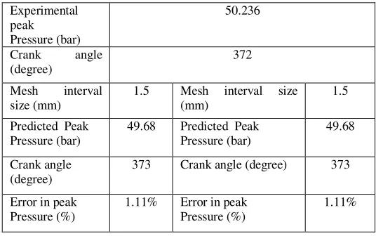
The test is conceded by trailing with a variety of grid sizes and surveillance how the solution revolutionizes concerning the changes in grid sizes. Finally, a stage will come when changing the grid spacing will not affect the solution. Solutions are assumed to converge when the following convergence criterion is satisfied at every point in the solution domain. Crevice volume is not considered here and the geometric compression ratio of the test engine is matched by adjusting the clearance volume of the mesh domain The mesh is composed of approximately 30,225 computational cells when the piston is at the Top-dead centre position, with a resolution of 2 mm. This mesh resolution is established to be fabricate the grid independent results, with comparatively high accuracy level and with a lesser computational runtime. Table 3 shows the experimental peak pressure value of the test engine operated with diesel fuel and the various predicted peak pressure values of the simulation when three mesh resolutions are tested for grid independency. The mesh of cell size with 2.5 mm resulted in the highest percentage of error of 2.1% between experimental and predicted values, followed by mesh resolution of 1.5 mm with 1.11% error and mesh resolution of 2 mm with 0.81% error. .
Table 3 Computational conditions of fuel injection for studied cases.
Experimental peak Pressure (bar)
50.236
Crank angle (degree)
372
Mesh interval size (mm)
1.5 Mesh interval size (mm)
1.5
Predicted Peak Pressure (bar)
49.68 Predicted Peak Pressure (bar)
49.68
Crank angle (degree)
373 Crank angle (degree) 373
Error in peak Pressure (%)
1.11% Error in peak Pressure (%)
1.11%
4
RESULTS AND DISCUSSIONS
The diesel engine utilized for the model validation is a single cylinder, four strokes, water cooled direct injection compression ignition engine. The engine arrangements are prearranged in Table 4 (De et al. 2014). The experiments are carried out in an entirely instrumented test engine with CR 17.5 at invariable speed of 1500 rpm, fuelled with diesel and 10% JME (volume basis). The main characteristics of the injection system are listed in Table 5. Table 6 describes the various physical, chemical and thermal properties of Diesel and 10% JME blend. The investigation engine is laden by attaching it with an eddy current sort dynamometer. On line performance assessment of the test engine is achieved by using the Labview based Engine Recital Investigation software package “EnginesoftLV”. A piezoelectric pressure transducer (pressure range 0-250 bars) and a charge amplifier is utilized to evaluate the cylinder pressure. Additional analysis is completed by utilizing the pressure data which are transferred and stored in the data acquisition system.
Table 4 Specification of the test engine.
S. No Parameters Specification
1. General Details
Single cylinder, four stroke compression ignition engine, constant speed, vertical, water cooled, direct injection
2. Stroke 110 mm
3. Bore 87.5 mm
4. Displacement 661 cc
5. Compression
ratio 17.5
6. Rated output 3.7 KW
7. Rated speed 1500 rpm
Table 5 Injector fuel system specifications.
S. No Injector type Common rail
1. Injection pressure Variable (up to 240 MPa)
2. Number of nozzle holes 6
3. Nozzle hole diameter 0.26 mm
4. Start of injection 230 BTDC
5. Injection duration 240 CA
6. Fuel injected 0.3196 g/cycle
Table 6 Properties of mineral diesel and 10% JME blend.
S. No Property Mineral
diesel JME10
1. Density (Kg/m3) 835 883.6
2. Kinematic viscosity at 400 C (cSt) 2 - 4 5.74
3. Flash point (0 C) 65 64
4. Calorific value (MJ/kg) 43.31 39.25
5. Cetane Number 45-55 NA
Angle measurement is made by utilizing a crank angle encoder (Kistler make) with an accuracy of 10. Mass flow meters are employed for quantifying the mass flow rate of JME blends and diesel in litters per minute. At beginning, the experiment engine is operated with
standard diesel for looking into the engine performance at full load circumstance and then parallel experiment is carried out with 10% JME which is organized on a volume basis. For all situations, by preserving the injection pressure of 203 bars and 23⁰ CA BTDC injection timing at rated speed of 1500 rev/min, the assessments are traced thrice and a mean of these is engaged for comparison. Then the data of experimental tests and the results from parallel simulation are judged against one another in terms of pressure traces, heat release rates.
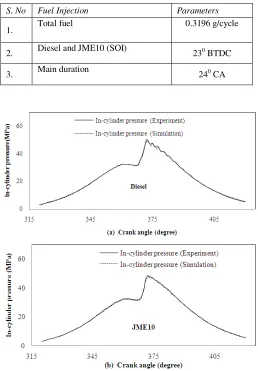
4.2 Cylinder pressure trace
Figure 2(a) illustrates the simulated and experimental in-cylinder pressure trace with respect to CA for baseline diesel and fig 2(b) for 10%JME blend. In all the injection cases studied, the same amount of fuel is injected in each engine cycle and describes in table 7. The consequence is supported on the supposition of consistent wall temperature 425 K for the cylinder wall, 525 K for the cylinder head and 525 K for the piston top. The predicted pressure data explains a good agreement with experimental data for both diesel and 10% JME blend, even though there is still some dissimilarity which can be seen in Fig. 2.
Table 7 Computational conditions of fuel injection for studied cases.
S. No Fuel Injection Parameters
1. Total fuel 0.3196 g/cycle
2. Diesel and JME10 (SOI) 230 BTDC
3. Main duration 240 CA
Fig. 2 Comparison of in-cylinder pressure between simulation and
experiments: (a) diesel fuel, (b) 10% JME blend (JME10).
rpm engine), hence the heat released in the cylinder and in-cylinder pressure (PMEP) is high. Diesel fuel is a light fuel and is easily atomized, vaporized and mixed with air raising its self-ignition temperature and reduces delay period. Improved combustion of the fuel-air mixture is increased the in-cylinder pressure (PMEP). On the other hand, JME10 blend, a viscous fuel increases the delay period resulting in lower in-cylinder pressure (PMEP) compared to that of diesel fuel. Lower calorific value of JME10 also can be accounted for producing lower peak temperature and pressure of engine cylinder evaluated to that of diesel fuel.
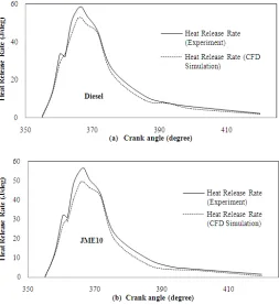
Fig. 3 Comparison of heat release rate between simulation and
experiments: (a) diesel fuel, (b) 10% JME blend (JME).
4.2 Heat Release Rate
Figure 3(a) exemplifies the predicted and experimental heat release rate relating to CA for baseline diesel and fig 3(b) for 10%JME blend. The forecasted heat release rate contests thoroughly with the investigational data for both diesel and 10% JME blend, even supposing there are still some variations which can be seen in Fig. 3. These disagreements could be connected to the experimental uncertainties in input parameters to the computations. At elevated engine load, enormous amount of fuel is injected (constant rpm engine), hence the heat released in the cylinder is high. Diesel fuel is a light fuel and the superiority of atomization lessens ignition lag, due to elevated surface volume ratio. Slighter droplet size will have little deepness of infiltration due to less momentum of the droplet and less velocity relative to air from where it has to find oxygen after vaporization. For the reason that this air exploitation factor will be lessened on account of the fuel spray path being shorter. Also with slighter droplets, the aggregate area of inflammation will augment after ignition, resulting in improved heat release rate compared to that of blending fuel. Lower calorific value of JME10 is also may be related to less heat release in the engine cylinder evaluated to that of diesel fuel. Fig. 4(a) represents the contours of static pressure of diesel fuel at 375 degree crank angle and (b) represents the velocity magnitude of 10% JME blend at 600 degree crank angle.
Fig. 4 Contours (a): static pressure of diesel fuel at 375 degree crank
angle, (b): velocity magnitude of 10% JME blend at 600 degree crank angle.
5
CONCLUSIONS
1. An integrated numerical model for diesel combustion has been investigated in this study. Good level of agreement is reported between computed and measured data for engine pressure trace and heat release rate for all the test cases, even though there are still some dissimilarities experimental and computed results. These disagreements could be associated with the experimental uncertainties in input parameters to the computations such as the precise injection duration, start of injection timing and gas temperature at IVC.
2. The pressure trace from the simulations is contained by an error fringe of only 10%, where the common trend of premixed and mixing-controlled diesel combustion phases is detained effectively.
3. The consequences of this study is of scrupulous interest to the automotive sector in an endeavour to lessen design-development time and cost. For example, outcomes of novel chamber geometries and functioning approaches could be experimented through this with elevated economical advantage.
NOMENCLATURE
CFD Computational Fluid dynamics ICE Internal combustion engine DI Direct injection
CR Compression Ratio CA Crank angle
JME10 10% Jatropha Methyl Ester and 90% Diesel oil in blend IVC Inlet Valve Closing
REFERENCES
Andreadis, P. A,. Zompanakis, C. and Kaiktsis, L., 2011, “Effects of fuel injection parameters on the performance and emissions in a large-bore marine diesel engine,” International Journal of Engine Research, 2(1), 14–29.
http://dx.doi:10.1243/14680874JER511
O’Rourke, P.J., 1981, “Collective prop Effects on vaporizing liquid Sprays,” PhD Thesis, University of Princeton.
Goldsworthy, L., 2006, “Computational fluid dynamics modelling of residual fuel oil combustion in the context of marine Diesel engines,” International Journal of Engine Research, 7, 181–99.
http://dx.doi:10.1243/146808705X30620
Struckmeier, D., Tsuru, D., Kawauchi, S., and Tajima, H., 2009, “Multi-component modeling of evaporation, ignition and combustion processes of heavy residual fuel oil,” SAE Technical Paper Series 2009-01-2677, SAE International Powertrains, Fuels and Lubricants Meeting. San Antonio, Texas.
Kyriakides, N., Chryssakis, C. and Kaiktsis, L., 2009, “Influence of Heavy Fuel properties on spray atomization for marine Diesel engine applications,” SAE Technical Paper Series 2009-01-1858, SAE International Powertrains, Fuels and Lubricants Meeting, Florence, Italy.
Herrmann, K., Kyrtatos, A., Schulz, R. and Weisser, G., 2009, “Validation and initial application of a novel spray combustion chamber representative of large two-stroke Diesel engine combustion systems,” ICLASS, Vail, Colora.
Herrmann, K., Rotz, B., Schulz, R., Weisser, G., Boulouchos, K. and Schneider, B., 2010, “ Reference data generation of spray characteristics in relation to large 2-stroke marine Diesel engines using a novel spray combustion chamber concept,” ILASS-Europe 2010, Brno, Czech Republic.
Garaniya, V., Goldsworthy, L., McWilliam, D., 2011, “Thermal cracking and polymerisation modelling of a single heavy fuel oil droplet,” Chemeca 2011, Sydney, Australia.
Liu, A.B., Reitz, R.D., 1993, “Modeling the Effects of Drop Drag and Break-up on Fuel Sprays,” SAE Paper 930072.
Dukowicz, J.K., 1979, “Quasi-Steady Droplet Change in the Presence Of Convection,” Informal Report Los Alamos Scientific Laboratory, LA7997-MS.
Naber, J.D., Reitz, R.D., 1988, “Modeling Engine Spray/Wall Impingement,” SAE Paper 880107.
Halstead, M., Kirsch, L., Quinn, C., 1977, “The auto ignition of hydrocarbon fueled at high temperatures and pressures-fitting of a mathematical model,” Combust. Flame, 30, 45–60.
ICE Physics & Chemistry, 2009. “AVL FIRE user Manual,” 1.
Colin, O. and Benkenida, A., 2004, “The 3-Zone Extended Coherent Flame Model (ECFM3Z) for Computing premixed/diffusion combustion,” Oil & Gas Science and Technology-Rev, IFP, 59, 593-609.
http://dx.doi.org/10.2516/ogst:2004043
Hélie, J., Trouvé, A., 2000, “A modified coherent flame model to describe turbulent flame propagation in mixtures with variable composition,” Proc. Combust. Inst, 28, 193–201.
De, B. and Panua, R. S., 2014, “CFD modeling and validation of combustion in direct injection compression ignition engine fuelled with jatropha oil blends with diesel,” Frontiers in Heat and Mass Transfer, 5(7).
http://dx.doi.10. 5098/hmt.5.7