THE NON-SCAN DELAY TEST ENRICHMENT BASED ON RANDOM
GENERATED LONG TEST SEQUENCES
Eduardas Bareiša
1, Vacius Jusas
1, K
ę
stutis Motiej
ū
nas
1, Rimantas Šeinauskas
1,2 1Kaunas University of Technology, Software Engineering DepartmentStudentų St. 50-406, LT-51368 Kaunas, Lithuania
e-mail: [email protected], [email protected], [email protected]
2Kaunas University of Technology, Information Technology Development Institute
Studentų St. 48A, LT-51368 Kaunas, Lithuania e-mail: [email protected]
Abstract. The paper investigates the possibilities of application of random generated test sequences for at-speed testing of non-scan synchronous sequential circuits. Our research shows that relatively long random test sequences exhibit better transition fault coverages than tests produced by deterministic ATPG tools. We proposed an approach for dividing of long test sequences into subsequences. The application of the presented approach allows increasing the fault coverage of the initial random generated test sequence, minimizing the length of the test by eliminating sequences that don’t detect new faults and determining, for particular circuit, the required length of the test sub-sequence which can be used for further construction of the test. The provided experimental results demonstrate the effectiveness of the proposed approach.
Keywords: sequential non-scan circuits, delay faults, random test generation.
1. Introduction
Sequential circuit testing has been recognized as the most difficult problem in the area of fault detec-tion. The difficulty comes from the existence of me-mory elements. With meme-mory elements, such as latches or flip-flops, the circuit output depends not only on the current inputs but also on the operation history (circuit states). Of course, it is possible to faci-litate sequential circuit testing by adding some extra hardware, which enhances the controllability and ob-servability of the circuit. However, the test hardware increases hardware overhead and can degrade circuit performance. Thus, before using valuable chip space, test generation without adding extra hardware should be tried [1].
High-performance circuits with aggressive timing constraints are usually very susceptible to delay faults. As the drive towards lower power processors conti-nues, the number of “critical” paths increase, i.e. the delay of such paths is close to the rated speed of the circuit. Small process variations and environmental changes (like temperature increase) may cause such circuits to fail at the rated clock speed. Testing high-performance circuits for timing failures is becoming very important [2].
A lot of work has been done in the area of delay testing for both combinational and sequential circuits.
Most of the proposed delay fault test techniques for sequential circuits involve test methods utilizing scan chains or variable clock speed test application. Insert-ing scan latches into designs is expensive in terms of chip real estate. On the other hand, testing non-scan circuits using variable clock speeds requires sophis-ticated testers and clock control circuitry. Due to these drawbacks, delay fault testing in industry has focussed on at-speed test application in non-scan or partial scan circuits [3].
In this paper, we are going to investigate the possi-bilities of application of random generated test se-quences for at-speed testing of non-scan synchronous sequential circuits.
The rest of the paper is organized as follows. We review the related work in Section 2. In Section 3, we describe the new approach to test enrichment based on random generated long test sequences. Section 4 pre-sents the experimental results, and Section 5 conclu-des the paper.
2. Related work
Only the primary inputs (PIs) of the circuit are cont-rollable and the primary outputs (POs) are observable. All the latches in the sequential circuit are synchroni-zed by a common clock. For delay fault testing of non-scan sequential circuits, test application consists of the following steps: (a) initialization of the circuit to a known state, (b) fault activation to stimulate the fault being tested and (c) propagation of the fault effect to a primary output (PO). It may require a num-ber of input vectors to initialize the circuit and to pro-pagate the fault effects to a PO.
In variable clock testing (which is also referred to as slow-fast-slow testing), it is assumed that the latches are clocked at a slower frequency during the initialization and the propagation periods, while fault activation is performed at the rated clock speed. Ex-cept for the fault-activation cycle, the circuit is assumed to operate in a fault-free manner and the slow clock period is chosen to ensure that all signals stabilize even if there are delay faults in the circuit. Variable clock testing of sequential circuits suffers from two main drawbacks. First, the testing hardware needs to be more sophisticated in order to be able to control the clock frequency during the test application. This can easily translate to a higher ATE cost or more on-chip hardware for routing and multiplexing the different clocks. Second, since fault activation is allowed only during the fast clock period, a large number of test sequences may be required to get suffi-ciently high delay fault coverage resulting in long test times.
The more economical alternative is to perform at-speed testing of delay faults in non-scan sequential circuits. At-speed test application has the advantage that the circuit is tested under its normal operation conditions. It has been shown that certain defects will only be detected if tests are applied at-speed [4]. Additionally, as demonstrated in [5], test application that deviates from normal operation can cause faulty behaviour that would not show up during normal ope-ration. However, correct activation and propagation cannot be guaranteed since delay faults may affect the outcome of more than one cycle, i.e. multiple fault activation or fault-masking may lead to erroneous results during the test. In general, the fault coverage for at-speed testing is lower than that for variable clock testing. Nevertheless, its simplicity of imple-mentation makes at-speed testing the methodology of choice for most industrial ICs [3].
Some relevant papers [6-15] devoted to testing of non-scan synchronous sequential circuits were publi-shed in recent years.
In paper [6], a new transition fault model for syn-chronous sequential circuits is proposed. Similar to previous models, this model also addresses the fact that delayed signal transitions span multiple clock cycles when a test sequence is applied to a synchro-nous sequential circuit at-speed. An advantage of this model is that it helps detect other types of faults that
require two-pattern tests, such as transistor stuck-open faults.
Another transition fault model for use with at-speed test sequences is defined in [7]. The model is referred to as the unspecified transition fault model since it introduces unspecified values into the faulty circuit when fault effects may occur. Fault detection potentially occurs when an unspecified value reaches a primary output. Due to the uncertainty that the unspecified value will be different from the fault-free value, an added requirement of this model may be that a fault would be detected multiple times.
The delay fault test for non-scan synchronous se-quential circuits could be constructed at the functional level using the software prototype model, as well [8-10]. Kang et al. [8] suggested the input/output tran-sition (TRIO) fault model for functional test selection at the register-transfer level (RTL). It is defined with respect to the primary inputs, primary outputs, and state variable of the module. However, this model is approximate because it does not stipulate toggle pro-pagation all the way to the primary outputs.
Bareiša et al. [9] introduced three different new fault models. According to the proposed models, the functional faults are considered on the primary inputs and primary outputs of the model only. The number of the functional faults is independent of the length of the clock sequence.
The paper [10] presents an approach of test ge-neration for non-scan synchronous sequential circuits based on functional delay models. The non-scan se-quential circuit is represented as the iterative logic array model consisting of k copies of the combina-tional logic of the circuit. The value k defines the length of clock sequence. The experimental results demonstrate the superiority of the delay test patterns constructed at the functional level using the functional fault models over the transition test patterns generated at the gate level by deterministic test pattern generator. Especially, the functional delay test generation method is useful for the circuits, when the long test sequences are needed in order to detect transition faults.
Random test sequences may be used for manu-facturing testing as well as for simulation-based design verification. It was shown in [11] that random primary input sequences achieve low fault coverage for synchronous sequential circuits due to the fact that they repeatedly assign the same values to subsets of state variables. To address this issue, in [11] a pro-cedure is described for modifying a random primary input sequence to eliminate the appearance of input vectors that synchronize subsets of state variables. It is demonstrated that this procedure has a significant effect on the fault coverage that can be achieved by random primary input sequences.
such that the resulting test sequence has as high fault coverage as possible. The test generation process thus searches a limited set of input vectors for an approp-riate order instead of exploring a search space that is limited only by the number of primary inputs of the circuit. However, only stuck-at faults are considered in both papers [11, 12].
An error propagation scheme for enhanced delay fault coverage in sequential circuits without full scan is proposed in [13]. The propagation of captured errors that represent delayed transitions has been treated in a pessimistic manner by previous implicit approaches. Such methods result in low fault coverage. The pro-posed method overcomes this drawback and guaran-tees exact coverage using appropriately generated functions. Exact coverage is obtained implicitly by forming error propagation functions with variables re-presenting the errors latched at the flip-flops. The authors claim that the delay fault coverage is signifi-cantly increased, more than 20%, over existing heuristic approaches.
For synchronous sequential circuits, one important issue is their initialization, which means the sequential circuit must start from a known initial state for it to operate correctly, as well as when generating tests for circuit, or when verifying the functional properties. The papers [14, 15] address to this problem.
In the paper [14], a heuristic searching method for logical initialization problem based on Max Min Ant System is presented. The algorithm employs a collec-tion of agents that collaborate to explore the primary input search graph. The limitation of this algorithm is that it is not able to identify uninitializable flip-flops.
A method for finding shortest length reset se-quences using circuit emulating software prototypes is proposed in [15]. The novelty and research value of the proposed method comes from using software that emulates circuits instead of using manufactured chips. Such a method does not use logical structure of the chip itself and test generation may start earlier in the manufacturing process.
3. An algorithm for dividing of long subsequences
Our experiments with non-scan synchronous se-quential circuits revealed that in many cases the deter-ministic automatic test pattern generation (ATPG) pro-duces tests which fault coverage is very low. Then we analysed the reasons of this phenomenon. We have revealed that the deterministic ATPG mostly fails when long test subsequences are needed for detection of faults. We define the term “subsequence” as fol-lows: the subsequence is a sequence of input patterns which starts with a set of initialisation patterns. Therefore, the subsequence is composed of two parts of input patterns: the first part Sub(In) is a set of initialisation patterns that lead the circuit to the known state and the second part Sub(test) is a set of test
pat-terns. The number of input patterns in Sub(test) de-fines the length of the subsequence.
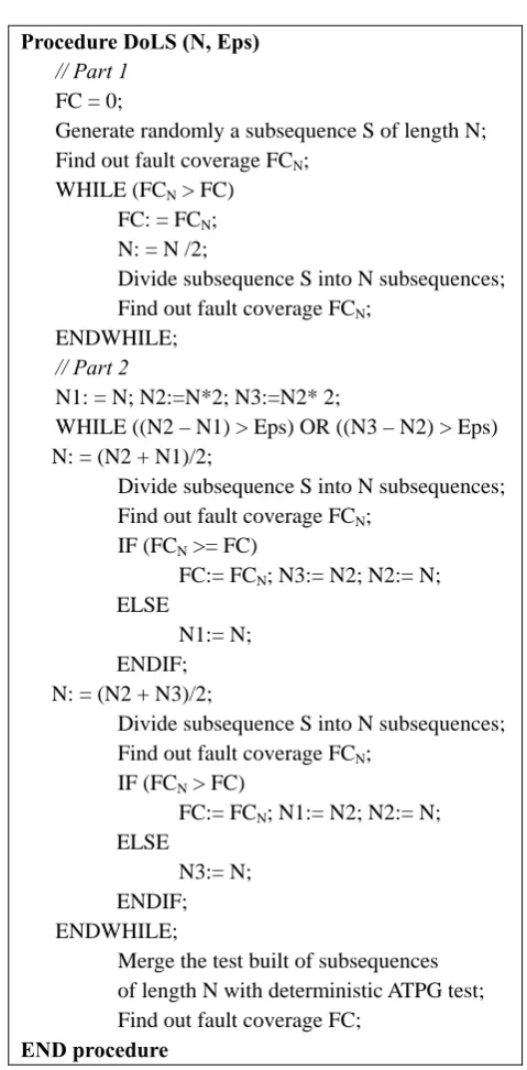
Procedure DoLS (N, Eps)
// Part 1
FC = 0;
Generate randomly a subsequence S of length N; Find out fault coverage FCN;
WHILE (FCN > FC) FC: = FCN; N: = N /2;
Divide subsequence S into N subsequences; Find out fault coverage FCN;
ENDWHILE;
// Part 2
N1: = N; N2:=N*2; N3:=N2* 2;
WHILE ((N2 – N1) > Eps) OR ((N3 – N2) > Eps) N: = (N2 + N1)/2;
Divide subsequence S into N subsequences; Find out fault coverage FCN;
IF (FCN >= FC)
FC:= FCN; N3:= N2; N2:= N; ELSE
N1:= N; ENDIF; N: = (N2 + N3)/2;
Divide subsequence S into N subsequences; Find out fault coverage FCN;
IF (FCN > FC)
FC:= FCN; N1:= N2; N2:= N; ELSE
N3:= N; ENDIF; ENDWHILE;
Merge the test built of subsequences of length N with deterministic ATPG test; Find out fault coverage FC;
END procedure
Figure 1. Pseudocode of the procedure DoLS
sensitize a new path and no new faults will be de-tected. Therefore, we divided the initial subsequence into smaller ones and determined again their fault coverages. The fault coverages have increased in al-most all cases.
Based on these findings, we developed a procedure for Dividing of Long Subsequences (DoLS). The pseudocode of this procedure is presented in Figure 1. Typically, the number of detected faults increases by dividing a long test subsequence into smaller ones, and it drops at some point. DoLS finds the dropping point in the first part of DoLS. The second part of the procedure DoLS is designed for searching of a more precise solution. A variable Eps defines the precision of solution. The outcome of the procedure DoLS is the length of the subsequence N, the test built of sub-sequences of length N plus deterministic ATPG test and the fault coverage of test, FC. Other variables of DoLS are internal variables. N1 is the length of sub-sequence at the dropping point of fault coverage. N2 is the smallest length of subsequence that gives the highest fault coverage at the current moment. The value of N3 is twice higher than value of N2. The length of the subsequence N lies between N1 and N3.
The application of procedure DoLS allows: 1) to increase the fault coverage of the initial random gene-rated test subsequence; 2) to minimize the length of the test by eliminating subsequences that don’t detect
new faults; 3) to determine, for particular circuit, the required length of the test subsequence which can be used for further construction of the test.
4. Experimental results
We present experimental results for the non-scan version of some ISCAS’89 and ITC’99 sequential benchmark circuits to demonstrate the effectiveness of the proposed approach. All ITC’99 benchmark circuits possess reset lines. Therefore, the set of initialisation patterns is comprised only of one reset pattern. The approach presented in [15] was used for generation of initialisation pattern sets for ISCAS’89 benchmark circuits. Synopsys TetraMAX was employed as deter-ministic ATPG. We consider transition faults.
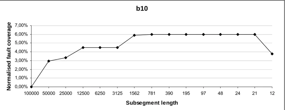
The typical dependence between subsequence length and fault coverage is presented in Figure 2. In the chart, the fault coverage is normalised for more evidence as follows: the obtained smallest fault coverage 73.25% is treated as zero. We got following values of variables N1=12, N2=24 and N3=48 after application of the part 1 of the procedure DoLS. The value of Eps was set to 1, because the fault coverage dropping point is at very low number (12). Finally, we got that the length of the subsequence is 21.
b10
0,00% 1,00% 2,00% 3,00% 4,00% 5,00% 6,00% 7,00%
100000 50000 25000 12500 6250 3125 1562 781 390 195 97 48 24 21 12
Subsegment length
N
o
rm
a
li
sed
fau
lt
co
ve
rag
e
Figure 2. Dependence of the fault coverage on the subsequence length
Recall that the variable Eps defines the precision of the solution. There is no sense to set Eps=1, when the dropping point N1 is at 1000 or more. For example, we got N1=1562 for circuit b13, therefore, the value of Eps was set to 50; and found that the length of subsequence for circuit b13 is 2986. Of course, we find in all cases only an approximate value of N, because the procedure DoLS is based on empirical computations.
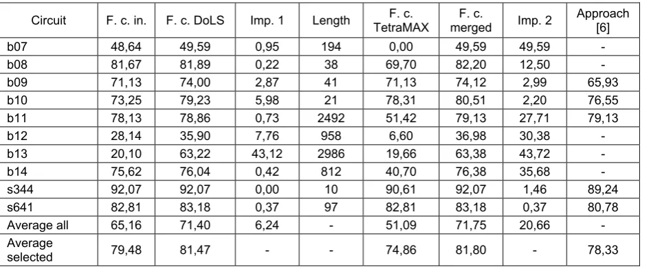
Results of application of procedure DoLS to seve-ral ISCAS’89 and ITC’99 sequential benchmark cir-cuits are shown in Table 1. For each circuit, circuit
row Average selected only data of the circuits b09, b10, b11, s344 and s641 are used for calculations. The
initial length of subsequence was 100000 random pat-terns for each of the considered circuits.
Table 1. Results of application of procedure DoLS
Circuit F. c. in. F. c. DoLS Imp. 1 Length TetraMAX F. c. merged F. c. Imp. 2 Approach [6]
b07 48,64 49,59 0,95 194 0,00 49,59 49,59 - b08 81,67 81,89 0,22 38 69,70 82,20 12,50 - b09 71,13 74,00 2,87 41 71,13 74,12 2,99 65,93 b10 73,25 79,23 5,98 21 78,31 80,51 2,20 76,55 b11 78,13 78,86 0,73 2492 51,42 79,13 27,71 79,13 b12 28,14 35,90 7,76 958 6,60 36,98 30,38 - b13 20,10 63,22 43,12 2986 19,66 63,38 43,72 - b14 75,62 76,04 0,42 812 40,70 76,38 35,68 - s344 92,07 92,07 0,00 10 90,61 92,07 1,46 89,24 s641 82,81 83,18 0,37 97 82,81 83,18 0,37 80,78 Average all 65,16 71,40 6,24 - 51,09 71,75 20,66 - Average
selected 79,48 81,47 - - 74,86 81,80 - 78,33
Pomeranz and Reddy claim that random primary input sequences could be used instead of deterministic ones to avoid sequential test generation, however, ran-dom primary input sequences achieve very low fault coverages [11, 12]. Our research shows that it is not true. Even one relatively long random test subse-quence exhibits better transition fault coverages than tests produced by deterministic ATPG tool TetraMAX as well as the tool presented by Pomeranz and Reddy in [6] (compare data in columns “F. c. in.“, „F. c. Tet-raMAX“ and „Approach [6]“). Our approach of divi-ding of long random test sequences into smaller ones allowed us to achieve more than 6% on average higher transition fault coverages than of initial test. The merging of TetraMAX tests with our tests increased the transition fault coverage from 51.09% to 71.75% on the average. Therefore, the presented experimental results demonstrate the effectiveness of the proposed approach. Of course, the main drawback of random test sequences is the length, and their application as stand-alone tests could be impractical. Therefore, we suggest to use deterministic tests as base and comple-ment them with random generated test subsequences. Such complementing would bring no shortening of the test length, if one long subsequence would be used. However, if the random generated test patterns are divided into subsequences, the minimization of test length can be done by eliminating subsequences that don’t detect new faults. Unfortunately, we don’t pos-sess such tool that would help to realise this statement.
5. Conclusions
We investigated the possibilities of application of random generated test sequences for at-speed testing of non-scan synchronous sequential circuits. Some re-searchers claim that random primary input sequences could be used instead of deterministic ones to avoid
sequential test generation, however, random primary input sequences achieve very low fault coverages. Our research shows that relatively long random test se-quences exhibit better transition fault coverages than tests produced by deterministic ATPG tools. We pro-posed an approach for dividing of long test sequences into subsequences. The application of our approach al-lows increasing the fault coverage of the initial ran-dom generated test sequence, minimizing the length of the test by eliminating subsequences that don’t detect new faults and determining for particular circuit the required length of the test subsequence which can be used for further construction of test. The provided experimental results demonstrate the effectiveness of the proposed approach. The complementing of Tetra-MAX tests with our tests increased the transition fault coverage at 21.5% on the average.
References
[1] W.B. Jone, N. Shah, A. Gleason, S.R. Das. PGEN: A Novel Approach to Sequential Circuit Test Generation. VLSI DESIGN, 4(3), 1996, 149-165. [2] A. Krstic, K.T. Cheng. Delay Fault Testing for VLSI
Circuits. Kluwer Academic Publishers, 1998.
[3] P. Pant, A. Chatterjee. Path-delay fault diagnosis in non-scan sequential circuits with at-speed test applica-tion. Proceedings of the International Test Conference
ITC 2000, 245-252.
[4] I. Pomeranz, S.M. Reddy. A delay fault model for at-speed fault simulation and test generation.
Procee-dings of the IEEE/ACM international conference on Computer-aided design, 2006, 89-95.
[5] J. Rearick, R. Rodgers. Calibrating Clock Stretch During AC Scan Testing. Proceedings of the
Interna-tional Test Conference ITC 2005, 266-273.
of integrated circuits and systems, 28(3), 2009, 426-432.
[7] I. Pomeranz, S.M. Reddy. Unspecified transition faults: a transition fault model for at-speed fault simu-lation and test generation. IEEE transactions on com-puter-aided design of integrated circuits and systems,
27(1), 2008, 137-146.
[8] J. Kang, S. C. Seth, V. Gangaram. Efficient RTL Coverage Metric for Functional Test Selection.
Pro-ceedings of the 25th IEEE VLSI Test Symposium, 2007, 318-324.
[9] E. Bareiša, V. Jusas, K. Motiejūnas, R. Šeinauskas. Functional Delay Clock Fault Models. Information
Technology and Control, 37(1), 2008, 12-18.
[10] E. Bareiša, V. Jusas, L. Motiejūnas, R. Šeinauskas. GeneratingFunctional Delay Fault Tests for Non-Scan Sequential Circuits. Information Technology and
Control, 39(2), 2010, 100-107.
[11] I. Pomeranz, S.M. Reddy. Primary input vectors to avoid in random test sequences for synchronous se-quential circuits. IEEE transactions on
computer-aided design of integrated circuits and systems, 27(1), 2008, 193-197.
[12] I. Pomeranz, S.M. Reddy. TOV: sequential test ge-neration by ordering of test vectors. IEEE transactions on computer-aided design of integrated circuits and systems, 29(3), 2010, 454-465.
[13] M. Kumar, S. Tragoudas, S. Chakravarty, R. Jay-abharathi. Exact delay fault coverage, in sequential logic under any daelay fault model. IEEE transactions
on computer-aided design of integrated circuits and systems, 25(12), 2006, 2954-2964.
[14] X. Hu, Z. Song, J. Wang, Y. Geng, W. Shen. Ant Colony Optimizations for Initalization of synchronous sequential circuits. Proceedings of the of the
Interna-tional conference on IEEE Circuits and Systems ICTD
2009, 5-18.
[15] K. Morkūnas, R. Šeinauskas. Circuit Reset Sequen-ces based on Software Prototypes. Elektronika ir
elektrotechnika – Electronics and electrical enginee-ring, 7(103), 2010, 71-76.