Purchased by the U. S. Departmen t of Agriculture 677 South Segoe Rd., Madison, Wis. 53711 USA For Official Us,
Soil Structure Evaluation With Audiofrequency Vibrations'
RON W. RICKMAN 2
ABSTRACT
Young's moduli for soils measured with a vibrational tech-nique varied with soil aggregate size, water content, texture, sensor-to-sample contact, and column handling. The magnitude of a Young's modulus varied from 10 7 dynes/cm2 (147 psi) for nearly saturated columns to over 109 dynes/cm2 for an air-dried, Na-saturated silt. The accuracy of the moduli measure-ments is in the order of 15% to 20%. The measured values compare favorably with others previously reported in the liter-ature for undisturbed and reworked soil samples. The range of measured soil moduli, the repeatability of the measurements, the lack of restriction on sample size and the nondestructive nature of the technique indicate that this procedure may pro-vide a useful measure for soil structure evaluation.
Additional Keg Words for Indexing: soil structure measure-ment, soil strength, soil elasticity.
on, STRUCTURE is defined somewhat differently by vari-ous authors. Bayer (1956, p. 123), states, "Soil struc-ture is usually defined as the arrangement of the soil par-ticles" (particles being either single or aggregates). Rose (1966, p. 109), recognizes some differences in the defini-tion: "The concept of soil structure has been defined in various ways, in broadest terms as the arrangement of solid particles in the soil profile." In Agricultural Handbook 60, Richards (1954, p. 60), is found an emphasis of the aggre-gates which the soil particles form: "The arrangement of soil particles into crumbs or aggregates that are more or less water stable is an important aspect of soil structure." The Soil Survey Manual, Soil Survey Staff (1951, p. 225), also points out the presence of aggregates as a part of the defi-nition of soil structure: "Soil structure refers to the aggre-gation of primary soil particles into compound particles, or clusters of primary particles, which are separated from adjoining aggregates by surfaces of weakness." In Agricul-tural Handbook 316, Gill and Vanden Berg (1967, p. 304), it is recognized that factors other than geometric particle arrangement are important as far as describing soil struc-ture is concerned: "The geometric arrangement of the solid material is generally called soil structure. Structure is an independent entity—the fortuitous arrangement of aggre-gates as influenced by total past history; therefore, struc-ture will have to be measured or identified."
Soil structure is a characteristic that has eluded quanti-tative measurement. Perhaps this is because the concept associated with soil structure generally is more inclusive than just a geometric arrangement of particles. The con-cept includes kinds, shapes, and sizes of particles present, the manner in which particles are held together, the degree
Contribution from the Northwest Branch, Soil & Water Conservation Research Division, ARS, USDA; Idaho Agr. Exp. Sta. cooperating, Received Aug. 11, 1969. Approved Oct. 13,
1969.
2 Research Soil Scientist, Pendleton Branch Experiment Sta-tion, Pendleton, Oregon 97801 (formerly at the Snake River Conservation Research Center, Kimberly, Idaho where research was accomplished).
to which they are held together and, usually, the response of these groups of particles to some manipulation or prob-ing of the soil. At some point this concept begins to overlap with another called soil strength as used in soil mechanics. The term soil structure as hereafter used in this paper refers to the broadest concept given in the previous para-graph with the exclusion of soil response to major manipu-lation. The major factors considered while attempting to describe soil structure as just defined will be the nature of particle-to-particle contact and bonding, the degree of this bonding, and the effect that this bonding has on the trans-mission of small magnitude stresses through a mass of soil particles.
A common approach to the analysis of soil structure has been to consider as a model of the soil a system of uniform spherical particles. This emphasis on the particulate nature of soils has perhaps led to a model that is more compli-cated than necessary to adequately describe soil structure. The spherical particle model is complicated by different types of packing, different sized beads, and ultimately different shaped beads. This, even in its most complicated form, bears only a slight resemblance to a soil of highly irregular shaped and sized particles.
Considering the general problem of soil structure de-scriptions, one might ask—is it really the geometric arrange-ment of particles about which one should be concerned? If one could determine the response of a system of particles to an applied force, is it necessary to know the geometric arrangement of the components? If not, what must one know about the system of particles to provide the informa-tion about the soil's response to an external force?
An important shortcoming of the particular model is its failure to adequately consider the nature of the particle-to-particle contact within the soil. The particle-to-particle-to-particle-to-particle bonds or interactions will largely control the gross reaction of the collection of particles. Therefore, a model that would emphasize this bonding would be advantageous in describing soil structure.
First consider a simple particle-to-particle contact (Fig. 1A). In most cases of agricultural interest the particles will be held together by water at the point of contact. In addi-tion, an organic or mineral cementing material may be present. As the amount of water between the particles changes, the forces holding the particles together would be expected to change and therefore the overall reaction of the particles to external forces would be expected to change. Any rigidity contributed by cementing materials or movement caused by slippage of particles past one another would also influence the reaction of the group of particles. This physical contact between these particles may be represented with a mechanical model of a spring and two dashpots in parallel (Fig. 1B). This type of model is that of a viscoelastic medium, one which exhibits both viscous and elastic properties. McMurdie (1963), and Wal-dron (1964) have shown that such a model does provide a
Chatve Amplifier Oscilloscope
VTVM
Accelerometer
Sample
lerometer
20 SOIL SCI. SOC. AMER. PROC., VOL. 34, 1970
Fig. 1—Model representation of soil particle-to-particle contact.
satisfactory description of soil behavior in some creep tests. Kondner and Ho (1965a, 1965b) have used a viscoelastic model in stress relaxation tests on soil. This model for soil behavior appears even more desirable since descriptive parameters or "constants" for samples can be evaluated by nondestructive vibrational testing techniques which have been fully developed for viscoelastic or elastic material.
A vibrational test of a soil sample should provide a measure of particle-to-particle contact and bonding. In order for a pulse or one cycle of a vibrational wave to travel from one end of a sample to the other, the pulse must be transmitted from one particle to another via the contact between them. The amount of energy lost by a wave as it moves through a soil will be determined pri-marily by the losses that occur at each contact. The number of contacts and amount of cementation or bonding at each one will affect energy loss. The amount of energy loss that occurs at each junction will also depend upon wavelength. This can be reasoned by considering a system of uniform sized particles. If a vibration frequency is selected such that nodes (zero displacement) occur at every point of contact, less attenuation would be expected than for a dif-ferent frequency that resulted in antinodes (maximum dis-placement) at points of contact. Each soil sample will have frequency transmission characteristics that will be determined by the sizes, arrangement, and type of contact of its component particles.
Each soil column, if it fits a viscoelastic or elastic model, will have a characteristic or resonant frequency which will be determined largely by those factors that are included in the concept of soil structure. From the resonant frequency
for a soil column and its height and density, a Young's modulus for the soil can be calculated. By including a measure of the amount of attenuation (energy loss within the sample) at that resonant frequency, the elastic modu-lus can be converted to a viscoelastic or complex modumodu-lus. Either or both of these parameters for a particular soil con-dition should, therefore, provide an index for soil structure.
As early as 1936 Ishimoto and Iida (1936, 1937) used a vibrational technique to test a variety of soil materials. More recently, vibrational testing methods have been used
Audio Audio Vibrator Oscillator Amplifier
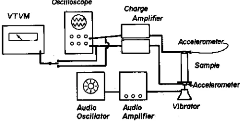
Fig. 2—Equipment and sample arrangement for elastic or vis-coelastic modulus measurement.
on sand by Hall and Richart (1963), Hardin and Richart (1963) and on clay samples by Kondner (1961) and in direct field applications by Johnson (1965) and US Army Engineers (1963).
The parameter most commonly measured with vibra-tional techniques is a "dynamic" modulus or a complex Young's modulus. A complex shear modulus can also be measured if shear waves rather than compressional ones are used. By using the equations of Ishimoto and Iida (1936) one can calculate a solid viscosity of a soil sample. A creep function, an attenuation constant and a mechanical imped-ance or a relaxation function as described by Eirich (1956) in his text on theology are other parameters which can also be evaluated. Which, if any, of these parameters will pro-vide the best description of the structure of an agricultural soil? This paper reports some laboratory vibrational mea-surements of complex Young's moduli and shear moduli of
packed samples of various soils. Results obtained are used to evaluate the procedure fox measuring soil structure.
PROCEDURE
The measurements reported in this paper are based upon the determination of a resonant frequency of a column with boun-dary conditions of a fixed bottom and a free top. Lee (1963) presented a complete theoretical development for this test pro-cedure. Figure 2 is a schematic of the instruments and sample arrangement used for the measurements. Stevens (1966) has also used this procedure.
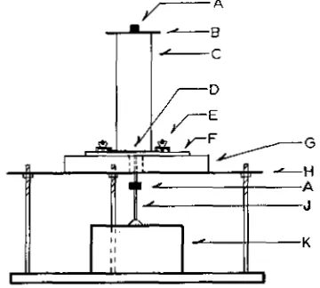
Fig. 3—Vibrational testing stand with soil column in place for resonant frequency measurement. Labels are A—accelerom-eter; B—top contact plate; C—soil column; D—base plate;
E—base plate damp; F—support disk; G—support sponge; H—support platform; J— connecting rod; K—vibrator. of the audio amplifier until a standard acceleration value (0,02 g) was obtained for the bottom of the column. The magnitude of the acceleration of the top of the column was then recorded. Near resonance the audio oscillator was tuned back and forth across the resonant frequency in order to obtain that frequency as precisely as possible.
In order to obtain measurements utilizing shear waves in-stead of compressional waves, a support apparatus slightly different from that in Fig. 3 was used. The metal disk that supported the soil column was held from beneath by a rod and bearing which allowed the disk to spin freely. Vibrations were imposed upon this disk by a rod inserted horizontally into its side and connected to a horizontally mounted electromagnetic vibrator. The amplitude of torsional vibrations was measured by accelerometers mounted a fixed distance from the central axis of the soil column. The accelerometers were mounted on the top metal contact plate and on the supporting disk and were positioned so to sense the torsional not compressional vibrations.
The quantities recorded for each sample measurement were (i) column height, (ii) column weight, (iii) column diame-ter, (iv) frequency of maximum amplitude ratio and (v) am-plitude of acceleration of both bottom and top of the column. The amplitude ratio is defined as the ratio of the amplitude of movement of the top of the column to the amplitude of move-ment of its base when the column is vibrated sinusoidally under the boundary conditions of fixed bottom and free top.
The equation used to calculate the magnitude of the com-plex modulus for a soil sample as presented by Stevens (1966) is:
E* 16f2L2 p (1 + tan2 )
x 2
tan
where E* is the magnitude of the complex modulus, f is the frequency at maximum amplitude ratio or resonant frequency, L is column height and p is wet density of the column, R max is the value of the maximum amplitude ratio, and x is called a loss angle. It is the angle by which strain lags stress during the vibrations at resonant frequency. The tan(x) is the ratio of the imaginary part (E") to the real (E') part of the complex modulus when it is expressed as a complex number E iE". The tan(x) is a measure of energy dissipation in the column. Measured values of R„x ranged from 4 to about 30. The quantity tan2 (x/2) was less than 0.05 for all samples used. E*
could therefore be approximated by E = 16f2L2p, the elastic modulus, to within 5% or better for the measurements re-ported in this paper. The accuracy to which each of the terms in the equation for the complex modulus can be measured
(with the exception of x) is 3% to 5%. If x is ignored, this provides a value for E* with a possible accuracy of 15% to 20%. The range of resonant frequencies found for the soil col-umns was from 50 Hz to about 300 Hz for compressional vibrations and from 30 Hz to 200 Hz for torsional vibrations. Six different soil materials were made into columns 6.1 cm in diameter and 15 to 30 cm high. The fine-textured samples were screened through a 0.5-mm screen. Sands were screened of organic matter larger than the sand particle size. Columns of the soils were formed in Saran Wrap lined split cylinders. After removal of the split cylinders each completed sample was, therefore, a soil column wrapped with Saran to maintain its shape. The Saran was presumed to have no influence on the soils or measurements. (Trade names and company names are included for the benefit of the reader and do not infer any endorsement or preferential treatment of the product listed by the US Department of Agriculture.)
The frequency of maximum amplitude ratio was determined for the dry columns. Each was then wetted from the bottom to near saturation. The columns were permitted to dry slowly as water evaporated from the ends. Periodic vibrational mea-surements provided an elastic modulus for each sample at several different average water contents. These moduli were plotted as a function of average water content for each soil.
Shear modulus values were obtained by providing a tor-sional vibration at the bottom of the sample columns rather than compressional vibrations which were used for Young's modulus determination. Resonant frequency for torsional vibra-tion was always lower than that for compressional resonant frequency and was unstable, particularly for wet columns.
To provide a measure of the repeatability possible with the technique, four replicate columns were made of Portneuf silt loam aggregates: (i) passing a 0.5-mm screen, (ii) passing a 2-mm screen but not a 1-mm screen, and (iii) a 1:1 mixture of (1) and (ii) by weight. The elastic modulus of each air-dry column was determined. Two columns of each set were then wetted and periodic measurements of elastic moduli attempted as the columns dried.
RESULTS AND DISCUSSION
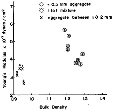
Even at the low strength of the dry Portneuf aggregate columns, measureable differences in moduli were present. Attempts to measure the moduli as the columns were wetted and redried failed because, except for the less than 0.5-mm aggregates, the columns were too fragile to pro-vide useable measurements without using excessive, time-consuming caution. There is a measureable difference among the dry replicate columns that elastic moduli indi-cate but bulk densities do not as shown in Fig, 4. Signifi-cant differences are present at the 5% level between the averages of the elastic moduli of the different aggregate combinations. Note that the elastic moduli order the col-umns differently and separate individual columns more than do bulk densities. The different order indicates that the finer aggregates tended to form a more rigid column than the mixed aggregates even though the mix had a higher bulk density.
30
• Loamy Fine Sa • Na-Si x Si Loam
•
• cs
Ro
ur 7
22 SOIL SCI. SOC. AMER. PROC., VOL. 34, 1970
O € 0.5 mm aggregate • Ito 1 mixture
X aggregate between 1 a 2 mm
5
4
iSd( 3 X 3
1.0 1.1 1.2 1.3 1.4 Bulk Density
Fig. 4—Elastic modulus and bulk density of replicate air-dry Portneuf silt loam aggregate columns.
parison with those of the author. Their values probably approach the maximum moduli measured on unconfined uncemented soil material. A basic trend which has already been pointed out by Ishimoto and Iida (1936, 1937) and Stevens (1966) is evident. The elastic modulus of a soil increases as the soil dries, except for coarse sand the modu-lus of which does not change appreciably throughout the water content range.
The elastic modulus changes over a much wider range in some soils than in others. The differences among the sodium-saturated silt, the consolidated silty clay, and the clay columns in Fig. 5B illustrate this. Some other charac-teristics of each soil are evident from the curves shown. Near saturation the Na-saturated silt slakes and, therefore, has a very small modulus value. The laboratory-formed clay column on the other, hand retains a larger modulus near saturation. As the soils dry, the Na-saturated silt and the consolidated silty clay column rapidly harden, as indi-cated by the slope of the lines connecting data points. The Na-silt column did not crack as it dried. The laboratory-formed clay column hardened Less rapidly as it dried and horizontal cracks formed in spite of the Long drying time (several weeks). The change in slope of the line at about 25% water for clay data points may indicate when the cracks became continuous enough to influence measure-ment.
The presence of horizontal (with column standing on one end) cracks in a column will have a major effect on measured values. In Fig. 5A are data from one of the Port-neuf aggregate columns which was found to be in three separate pieces when examined. The first few data points from this column tend to parallel those of the other silt loam. After what was apparently the development of the major horizontal cracks, the modulus values by their irregu-larity reflected only the presence of cracks—not properties of soil.
Young's moduli were more consistent and varied over a wider range than did shear moduli. The shear moduli in Fig. 6 do show a difference between soil samples, however. It would seem that shear moduli might 'provide a good
0 10 20 30 40 10 20 30 40 50 10 20 30 48 0
PERCENT WATER BY WEIGHT
Fig. 5—Young's modulus vs. water content for soil columns. In section A (Si L) data were for a silt loam subsoil and the
(Si L Broken) column was made from 1/2 mm Fortneuf silt-loam aggregates, In section B the clay was from the B
hori-zon of a soil collected in Idaho. (Silt-Na sat.) was a Na saturated silt from Nevada. In section C (Coarse Sa) was a washed (1 mm) sand and the loamy fine Sa was from Idaho. Data for undisturbed cores of a consolidated clay
subsoil collected by Ishimoto and Lida (1936) were included
(in section B) to provide a comparison with the reported measurements.
q 10 20 3q 4q
PERCENT WATER BY WEIGHT
Fig. 6—Shear modulus vs. water content for disturbed soil
columns.
numerical index for a soil's water stability. As a soil be-comes saturated, if it slakes, it should lose much of its shear strength. Insufficient measurements were taken on near-saturated columns to test this idea.
Table 1-Resonant frequency and loss angle for two laboratory
packed soil columns
5 water (dry wt. baste)
Resonant
freemOoky (f) Amplitattle {Re) rats* (R ma,,)
Loss angle (x) (degrees) Silt loam
31 71 14 6.2
29 121 9 8, 1
16 160 13 5, 6
12 175 13 5.6
222 22 3.2
Loamy fine sand
23 68 7 10. 4
19 84 10 7. 2
14 98 17 4.3
12 114 5 14.5
7 148 13 5.6
5 16.2 10 7. 3
ent upon the nature of contact between the top acceler-ometer plate and the soil column. This contact was not repeatable for every measurement. As the soil columns dried the shape of the column top changed slightly and adhesion between the plate and soil column decreased con-siderably. If uniform or repeatable sensor contact could be established one should be able to use values of .x or tan(x) to characterize energy loss within soil columns.
Aside from being an index for soil structure or stability, elastic moduli can be used to calculate other soil proper-ties. If one analyzes soil cracking in terms of the rupture of an elastic medium by utilizing Griffith's (1920) cracking theory, the range of values of the elastic modulus of a soil provides part of the numerical information needed to cal-culate cracking parameters. Attempts to use elastic theory or some modification of it to describe soil behavior have been limited primarily to engineering applications such as Rostron (1967), US Army Engineers (1967), Johnson (1965), Ishimoto and Lida (1936), Hardin and Richart (1963), and Hall and Richart ( /963).
Elastic theory must be restricted to conditions of small strain in any medium to which it is applied. For this reason it has been used successfully in engineering practice only where it is applied to highly compacted soils. In order to study mechanical behavior of soil in more detail and to determine the changes in structure and other properties
that occur as force is applied to a compressible soil, more flexible theories of material behavior such as the viscoelas-ticity theory used or described by Eirich (1956), Kondner and Ho (1965a, 1965b), and Waldron (1964) will have to be used. If one is only interested in characterizing soil structure as a static property of a soil (in comparison to a soil mechanics characterization that is intended to describe a soil's response to a force), it appears that a simple elastic modulus for the soil will provide a useable index.
Throughout this paper the term modulus was used in preference to elastic "constant." The purpose of this delib-erate omission of the word constant was to avoid the mis-conception that soil structure can be characterized by a single "constant" number. The structural properties of a soil change as any of a large number of factors change. The range of modulus values exhibited by a soil in various con-ditions and the manner in which the modulus changes with each controlling factor are therefore needed to characterize its structure.
CONCLUSIONS
Vibrational evaluation of soil structure has several advan-tages over previously used methods. Measured elastic mod-uli have a wide range of values (107 to over 109 dynes/cm2 with a possible accuracy of 15%) which appear to be
dependent upon those factors considered to determine soil
structure-particle or aggregate size, bulk density, water content, and the presence or absence of cementing or stabilizing materials. Moduli for different textured soils
change differently as water content of the samples
de-creases. Measured moduli compare favorably with those
reported by other authors for undisturbed or compacted
samples. Elastic moduli can be used to calculate other soil properties. There is relatively little restriction on sample size with this technique. Any cylindrical sample from 5 to 10 cm in diameter with height greater than diameter can be used. The same sample can be measured repeatedly at different water contents. This eliminates the need for large numbers of samples in any study of the change in structure or strength with water content. Undisturbed cores can be used as readily as disturbed columns.
LITERATURE CITED
1. Bayer, L. D. 1956. Soil physics, 3rd ed., John Wiley & Sons, Inc., New York, 489 p.
2. Eirich, Frederick R. 1956. Ed., Rheology: Theory and applications, Academic Press, Inc., New York, 761 p. 3. Gill, William R. and Glen E. Vanden Berg 1967. Soil
dynamics in tillage and traction. USDA Agriculture hand-book 316, Washington D.C., 511 p.
4. Griffith, A. A. 1920. The phenomena of rupture and flow in solids. Philosophical Transactions, Royal Society, Lon-don 221 (series A):163-198.
5. Hall, J. R. Jr., and F. E. Richart, Jr. 1963. Dissipation of elastic wave energy in granular soils. J. Soil Mech. Found. Div. ASCE 89-SM6:27-56.
6. Hardin, B. 0., and F. E. Richart, Jr. 1963. Elastic wave velocities in granular soils. J. Soil Mech. Found. Div. ASCE, 89-SMI:33-65.
7. Ishimoto, Mishio, and /Cumin lida. 1936. Determination of elastic constants of soils by means of vibration methods. Part 1. Young's modulus. Bull. Earthquake Res. Inst. Tokyo Univ. 14:632-656.
8. Ishimoto, Mishio, and Kamizi Lida. 1937. Determination of elastic constants of soils by means of vibration methods. Part 2. Modulus of rigidity and Poisson's ratio. Bull. Earth-quake Res. Inst. Tokyo Univ. 15:67-85.
9. Johnson, L. E. 1965. Sonic method for the determination of soil properties, Summary report July 1, 1964 to August 31, 1965, for Bureau of Public Roads, contract No. CPR-11.8026, CFSTI no. PB 177 483.
10. Kondner, Robert L. 1961. Vibratory simple shear of a clay, Highway Res. Board Proc. 40:647-662.
11. Kondner, Robert L., and Michael M. K. Ho. 1965a. Com-plex modulus of a cohesive soil from a stress relaxation response using the onesided fourier transform. J. Appl. Phys. 36:2119-2124.
12. Kondner, Robert L., and Michael M. K. Ho. 1965b. Vis-coelastic response of a cohesive soil in the frequency domain, Trans. Soc. Rheol. 9:329-342.
13. Lee, Tung-Ming. 1963. Method of determining dynamic properties of viscoelastic solids employing forced vibra-tion. J. Appl. Phys. 34:1524-1529.
14. McMurdie, John L. 1963. Some characteristics of the soil deformation process. Soil Sci. Soc. Amer. Proc. 27:251-254.
SOIL SCI. SOC. AMER. PROC., VOL. 34, 1970
24
16. Rose, C. W. 1966. Agricultural physics, Pergamon Press, New York, 226 p.
17. Rostron, Joseph P. 1967. Elasticity Relationships of Peid-mont Subgrades, Clemson Univ. S. C. Engr. Expt. Sta. Res. Bull. 110.
18. Soil Survey Staff. 1951. Soil survey manual. USDA Agri-culture Handbook 18. Washington D.C., 503 p.
19. Stevens, H. W. 1966. Measurement of the complex moduli and damping of soils under dynamic loads. Laboratory test
apparatus procedure and analysis. Technical Report 173. Cold Regions Research and Engineering Laboratory, CFSTI # AD 484 956.
20. US Army Engineers. 1963. A procedure for determining elastic moduli of soils by field vibratory techniques. Waterways Experiment Station Miscellaneous Paper no. 4-577. Corps of Engineers, Vicksburg, Mississippi. CFSTI #AD 409 826.