Improve Routing Process with Feature Based
Packet Transmission Technique in MANET
using GRBR Algorithm
R.Navinkumar, MCA.. N.Prabaharan (Final MCA).,
Assistant Professor, Department of Computer Application, Nandha Engineering College, Erode, Tamil Nadu, India.
Abstract—As wireless communication gains popularity, significant research has been devoted to supporting real-time transmission with stringent Quality of Service (QoS) requirements for wireless applications. At the same time, a wireless hybrid network that integrates a mobile wireless ad hoc network (MANET) and a wireless infrastructure network has been proven to be a better alternative for the next generation wireless networks. By directly adopting resource reservation-based QoS routing for MANETs, hybrids networks inherit invalid reservation and race condition problems in MANETs. How to guarantee the QoS in hybrid networks remains an open problem. In this paper, we propose a QoS-Oriented Distributed routing protocol (QOD) to enhance the QoS support capability of hybrid networks. Taking advantage of fewer transmission hops and anycast transmission features of the hybrid networks, QOD transforms the packet routing problem to a resource scheduling problem. QOD incorporates five algorithms: 1) a QoS-guaranteed neighbor selection algorithm to meet the transmission delay requirement, 2) a distributed packet scheduling algorithm to further reduce transmission delay, 3) a mobility-based segment resizing algorithm that adaptively adjusts segment size according to node mobility in order to reduce transmission time, 4) a traffic redundant elimination algorithm to increase the transmission throughput, and 5) a data redundancy elimination-based transmission algorithm to eliminate the redundant data to further improve the transmission QoS. Analytical and simulation results based on the random way-point model and the real human mobility model show that QOD can provide high QoS performance in terms of overhead, transmission delay, mobility-resilience, and scalability.
1 INTRODUCTION
The rapid development of wireless networks takes stimulated numerous wireless applications that take remained used in wide areas such as trade, emergency services, equipped, education, then entertainment. The sum of WiFi capable mobile devices including laptops then handheld plans (e.g., smartphone then tablet PC) has been increasing rapidly. For example, the number of wireless
Internet users consumes tripled world-wide in the previous three years, then the number of smartphone users in US has increased since 92.8 million in 2011 to 121.4 million in 2012, before will reach around 207 million by 2017 [1]. Now, people wish to watch videos, play games, watch TV, before make long distance conferencing via wireless mobile devices “on the go.” So, audiovisual streaming applications such as Qik [2], Flixwagon [3], and FaceTime [4] on the substructure wireless networks have received increasing care lately. These applications usage an substructure to straight connect mobile users for video viewing or contact in real time. The widespread use of wireless then mobile devices formerly the increasing appeal for mobile multimedia graceful services remain leading to a talented near future anywhere wireless multimedia services (e.g., mobile gaming, online TV, then online meetings) remain widely organized. The emergence then the intended future of real time and.
Multimedia applications consume stimulated the need of high Quality of Service (QoS) support in wireless then mobile schmoozing environments [5]. The QoS support reductions end to-end broadcast delay then improves quantity to assurance the seamless statement amid mobile devices then wireless substructures.
MANET to feast the coverage of the base stations, if continuous network connections.
How to declaration the QoS in hybrid wireless networks by high mobility and altering bandwidth still leftovers an open question. Now the infrastructure wireless networks, QoS provision (e.g., Intserv [10], RSVP [11]) has been future for QoS routing, which frequently requires node assistance, admission control, resource reservation, then priority preparation of packets [12So, attempts to directly adjust the QoS solutions for infrastructure networks to MANETs usually do not have uncountable success [13]. Frequent reservation-based QoS routing protocols consume been proposed for MANETs [14], [15], [16], [17], [18], [19], [20], [21] , [22] that make routes formed by nodes then links that standby their capitals to achieve QoS requirements. Though these procedures can increase the QoS of the MANETs to a sure extent, they hurt from invalid booking and race disorder problems [12]. Illegal reservation problem means that the reserved capitals develop useless if the data broadcast path between a source node then a terminus node breaks.
Now order to improve the QoS support ability of hybrid networks, in this paper, we suggest a QoS-Oriented Distributed routing protocol (QOD). Typically, a cross network has extensive base stations. In this paper, we emphasis on the neighbor node selection for QoS-guaranteed transmission. QOD is the first effort for QoS routing in hybrid networks. This paper brands five contributions. . QoS-guaranteed neighbor selection algorithm. The
algorithm selects qualified neighbors and employs deadline-driven scheduling device to guarantee QoS routing.
. Distributed packet scheduling algorithm. After fit neighbors are identified, this algorithm agendas packet routing. It allocates earlier generated packets to forwarders with higher queuing delays, while allots more recently made packets to
. Soft-deadline based forwarding scheduling algorithm. In this algorithm, a middle node first onwards the packet with the smallest time allowed to wait earlier being forwarded out to attain fairness in packet forwarding.
. Data redundancy elimination based transmission. Due to the broadcasting feature of the wireless networks, the APs then mobile nodes can overhear then cache packets. This algorithm removes the redundant data to recover the QoS of the packet transmission.
2 THE QOD PROTOCOL
2.1 Network and Service Models
We reflect a hybrid wireless network by an random number of base stations dispersal over the network. N mobile nodes stay moving around in the network. Apiece node n i ð1 i NÞ uses IEEE 802.11 border with the Hauler Sense Multiple Access with Crash Avoidance (CSMA/CA) protocol. So, the base stations careful in this paper are access points (APs). The WiFi border enables nodes to communicate with both APs and mobile nodes. For example, in a University campus, normally only buildings have APs. So, people that do not have WiFi access then close to buildings can use two-hop transmit transmissions to connect to the APs in the buildings. Feeney et al. careful the similar scenario in his work.
We use Ri and Ri to mean the packet transmission range then transmission interference range of node
ni, correspondingly. We use di;j to denote the distance amid nodes ni and nj. A packet transmission after ni to nj is successful if both situations below are content [30]: 1) di;j Ri, and 2) slightly node nk satisfying dk;j R0k is not transmitting packs, where 0 < k < N and k 6¼ j. Table 1 lists the symbols used in this paper for reference.
Fig. 1. The network model of the hybrid networks.
The QoS requirements mostly include end-to-end delay certain, which is vital for many applications by severe real-time requirement. While quantity guarantee is also important, it is automatically certain by bounding the transmission delay for a certain quantity of packets. Fig. 1 shows the network model of a hybrid network. For example, once a source node n1 wants to upload
files to an Internet server through APs, it tin choose to send packets to the APs directly by itself or require its neighbor nodes n2, n3, or n4 to backing
the packet transmission.
2.2 An Overview of the QOD Protocol
node, a neighbor node ni with space usefulness less than a verge replies the source node. The reply message covers information around available capitals for checking packet scheduling viability (Section 2.4), packet influx interval Ta, transmission stay TI!D, then packet deadline Dp of the packets in each flow being advanced by the neighbor for line up delay estimation and dispersed packet scheduling (Section 2.5) then the node’s mobility speed for decisive packet size (Section 2.6). The individual packets are advanced to the neighbor nodes that are scheduling feasible in a round-robin style from a longer delayed node to a shorter delayed node, pointing to reduce the whole packet transmission delay. Algorithm 1 displays the pseudo code for the QOD routing protocol performed by each node.
Algorithm 1. Pseudocode for the QOD routing protocol executed by a source node.
1: if receive a packet forwarding request after a source node then
2: if this.SpaceUtility
<threshold then 3: Reply to the source node.
4: end if 5: end if
6: if receive forwarding appeal replies for neighbor nodes then
7: Determine the packet size SpðiÞ to each neighbor i based on Equation (5).
8: Estimate the queuing delay Tw for the packet aimed at each neighbor based on Equation (4).
9: Control the qualified neighbors that can satisfy the deadline requirements based on Tw
10: Sort the qualified nodes in descending order of Tw
11: Allocate workload rate Ai for each node based on
Equation (3).
12: for each intermediate node n i in the sorted list do
13: Send packets to n i with transmission interval S
ApðiiÞ . 14: end for 15: end if
The packets travel from different APs, which may lead to different packet transmission delay, resulting in a jitter at the receiver side. The jitter problem can be solved by using token buckets mechanism at the destination APs to shape the traffic flows. This technique is orthogonal to our study in this paper and its details are beyond the scope of this paper.
Before introducing the details of QOD in the system, we justify that QOD is feasible to be used in a network with the IEEE 802.11 protocol in Section 2.3. We then present the details of QoS by
answering the following questions in QoS routing in hybrid networks.
1. How to choose qualified neighbors for packet forwarding? (Section 2.4)
2. How to schedule the packets to the qualified neighbor nodes? (Section 2.5)
3. How to ensure the QoS transmission in a highly dynamic situation? (Section 2.6)
4. How to schedule the packets in the relay node in forwarding to destinations? (Section 2.7)
5. How to reduce the data redundancy in transmission to further enhance QoS? (Section 2.8)
2.3 Applicability of the QOD Distributed Routing Algorithm
The QOD spread routing algorithm is developed founded on the assumption that the neighboring nodes in the network have different channel utilities and assignments using IEEE 802.11 protocol. Then, there is no need for packet scheduling in routing, since all neighbors produce
Fig. 2. Interference between two neighboring nodes.
Relative delay for packet forwarding.
2.3.1 Theoretical Analysis of Channel Utility and Workload Differences
Now order to avoid average access contention and hidden terminal problem, IEEE 802.11 uses the CSMA/CA protocol as MAC access control protocol. Earlier a node sends out packets, it sends a Appeal To Send (RTS) message to the next hop node indicating the duration time of the subsequent transmission. The destination node responds with a Clear To Send (CTS) message to establish a joining with the source node. The neighbor nodes hearing RTS and/ or CTS set their Virtual Carrier Sense indicator (i.e., Network Allocation Vector (NAV)) to the communication’s transmission duration time, so that it can evade transmitting data into the channel inside the time duration. We define
channel usefulness as the fraction of time a channel is busy over a unit time.
to signify the interference area of ni that is not met with that of nj, use <IðnjÞ to signify the interference area of nj that is not overlapped by that of ni, then use <Iðni;njÞ to mean the met region of the meddling regions of ni and nj.
2.4 QoS-Guaranteed Neighbor Selection Algorithm
As short delay is the main real-time QoS requirement for traffic transmission, QOD incorporates the Earliest Deadline First scheduling algorithm (EDF), which is a deadline determined scheduling algorithm for data traffic scheduling in central nodes. Currently this algorithm, an central node assigns the highest priority to the packet with the closest deadline and forwards the packet by the highest priority first. Lease us use SpðiÞ to denote the size of the packet vapor after node ni, use Wi to denote the bandwidth of node i, then TaðiÞ to denote the packet influx interval from node ni.
Similar to the random early detection (RED) algorithm in which a line length threshold is set to avoid queuing congestion, we set up a space usefulness threshold TeUs for each node as a care line to make the queue scheduling feasible.
When the source node controls the Nq nodes that can content the deadline obligation of the source node, the source node needs to allocate its packets to the Nq nodes founded on their available workload rate UasðiÞ Wi to brand the scheduling possible in each of the neighbor nodes.
For example, suppose the bandwidth Wi of the middle node ni is 70 kb/s, the verge of the workload is 80 percent of the general space utility, which is 56 kb/s. Node ni schedules the packet traffic after three different source nodes n1, n2, and n3
sometimes. The packet size of traffic
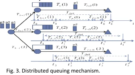
Fig. 3. Distributed queuing mechanism.
From n1, n2, then n3 are 1, 10, and 20 kb with
arrival interval
0.1, 0.5, and 1 s, respectively. Then, ST11 þ
S T22 þ
S
T33 ¼ 50 kb/s. Once another node n4 sends a request
to the middle ni,
2.5 Distributed Packet Scheduling Algorithm
Section 2.4 solves the problem of how to select intermediate nodes that can guarantee the QoS of the packet transmission and how a source node assigns traffic to the intermediate nodes to ensure their scheduling feasibility. This algorithm
allocates earlier generated packets to forwarders with higher queuing delays and scheduling viability, while assigns more recently generated packets to forwarders with lower line up delays and scheduling feasibility, so that the transmission delay of an entire packet brook can be reduced.
Below we introduce how to calculate Tw. Recall that QOD incorporates the EDF in which an intermediate node assigns the highest priority to the packet with the closest deadline and forwards the packet with the highest priority first. An middle node can control the priorities of its packets founded on their deadlines Dp. A packet with a lesser priority value x has a progressive priority.
If the queuing delay in each middle node satisfies then packet p1 must be sent to the first
middle node, packet p2 must be sent to the second
middle node, then packet p3 should be sent to the
third intermediate node. As a result, the final packet distribution time for the three packets after the intermediate nodes to the terminus node can be reduced.
As the quantity in two-hop transmission is usually less than the throughput of direct broadcast, the two-hop transmission is only used in two cases: 1) once the packet sender is out of the range of an AP, and 2) APs in range are overfilled. In these two cases, the direct communication to an AP cannot provide QoS guarantee, and the two-hop transmission is needed.
2.6 Mobility-Based Packet Resizing Algorithm
2.7 Soft-Deadline-Based Forwarding Scheduling
Memory that in the EDF algorithm, an middle node forwards the packets in the order after the packets by the closest limits to the packets by the farthest deadlines. If an middle node has no problem to meet all packets’ limits in forwarding, that is, the packets are scheduling feasible, the EDF algorithm works acceptably. Though, once an intermediate node has too many packets to onward out and the limits of some packets must be missed, EDF forwards out the packets with the closest limits but may delay the packets with the farthest deadlines. So, EDF is suitable for
hard-deadline driven requests (e.g., online conferences) anywhere packets must be forwarded earlier their deadlines but might not be fair to all arriving packets in soft-deadline driven applications (e.g., online TV), anywhere the deadline
missing is sometimes satisfactory.
Fig. 4. An example of packets received by the forwarder.
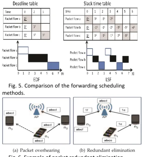
The tables in Fig. 5 show the deadline then slack time at each second for apiece packet, and the figures underneath show the forwarding preparation results of EDF and LSF. In the tables, we use the superscript to denote the packet order number. For example, in the deadline table, in the line of “packet flow a,” 21 at time 0 income that the
limit of the first packet of packet flow a is 2 at time 0. Likewise, in the slack time table, in the line of “packet flow a,” 01 at time 0 means that the slack
time of the firstly packet of packet flow a is 0 at time 0. The slack time 01 at time 0 is intended by subtracting current time 0 then the remaining transmission time 2 from the deadline 2. The leaden color means that this packet has the smallest deadline or slack time then is chosen to be advanced. A bold value with underline means it is for the afresh arrived packet.
2.8 Data Redundancy Elimination
As we presented in Section 2.3.1, the mobile nodes set their NAV values based on the eavesdropping message’s broadcast duration time. A large NAV leads to a small obtainable bandwidth then a small scheduling feasibility of the mobile
Fig. 5. Comparison of the forwarding scheduling methods.
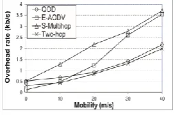
Fig. 6. Example of packet redundant elimination.
nodes based on (2). So, by reducing the NAV value, we can increase the preparation feasibility of the intermediate nodes then sequentially upsurge the QoS of the packet broadcast. Owing to the distribution feature of the wireless networks, in a cross network, the APs and mobile nodes can above and cache packets, we use an end-to-end traffic redundancy elimination (TRE) algorithm to eliminate the redundancy data to recover the QoS of the packet transmission in QOD
Fig. 6 shows an example of packet redundant removal in hybrid networks. By way of shown in Fig. 6a, when node n1 sends a message “abcd” to a
nearby AP finished n2, n3 overhears the message
then caches a chunk “abc” in its local memory. The AP earpiece also caches the message. Advanced on, once n3 sends a message “abcf” then n1 sends a
message “abce” to the AP, meanwhile they know the AP has cached “abc,” they only need to direct “1f” or “1e,” where “1” is the signature of the chunk “abc.” Formerly, the AP is able to rebuild the full chunk using his signature. The reduction in the size of the message upsurges the scheduling viability of the mobile nodes, which further improves the QoS presentation of the system.
3 PERFORMANCE EVALUATION
a node’s routing table. To apply E-AODV in hybrid networks, we let a source node
Fig. 7. QoS throughput versus mobility.
Now the imitation, the setup was the similar as Section 6. Six APs with IEEE 802.11 MAC protocol are consistently distributed in the area. We arbitrarily selected two basis nodes to send packets to APs in every 10 s. A node’s traffic is produced with continuous bit rate (CBR) sources. The generation rate of the CBR circulation is 100 kb/s. Except otherwise quantified, the speeds of the nodes were arbitrarily selected from [1-40]m/s. Meanwhile the number of successfully transported packets within a sure delay is critical to the QoS of video flowing applications, we describe a new metric, namely QoS certain throughput (QoS quantity in short), that events the throughput sent after a source node to a terminus node sustaining a QoS delay requirement as 1 s. This metric can concurrently reproduce delay, throughput, and jitter topographies of packet transmission. We straight use the verge parameter in RED queue as our space usefulness threshold. We track each experimentation for 10 times. We first selected the imitation results within sureness interval of 95 out of a hundred of the ten simulations, and then calculated the average result as the final result. The preparation time was set to 100 s then the simulation time was set to 200 s per round.
3.1 Performance with Different Mobility Speeds
In this experimentation, a node’s mobility rapidity was randomly selected after ½1;xm/s ðx ¼
1;10;20;30;40Þ. Fig. 7 conspiracies the QoS throughputs of all schemes versus the node flexibility speed. He shows that the QoS throughputs of all systems reduction as node mobility increases. This is since higher flexibility causes higher recurrent link breakages, which leads to more packet drops.
We can also see that the QoS quantities of QOD then Two-hop somewhat decrease, nonetheless persons of E-AODV then S-Multihop decrease abruptly. E-AODV then S-Multihop consume much additional hops in the steering paths from the source nodes to APs than QOD and Two-hop. A lengthier routing trail produces higher likelihood of link collapse during the packet broadcast. As Two-hop then QOD only have two Two-hops in the
direction-finding paths to APs, the small paths have lower likelihood to break down. Smooth if a link breaks down, the source node container quickly choose another forwarder. So, node flexibility does not importantly touch these two protocols.
Fig. 8. Fraction of QoS throughput versus mobility.
We define the portion of QoS throughput (QoS fraction in short) by way of the ratio of QoS throughput to total packet throughput. This metric shows the efficiency of different systems in secondary QoS routing. Fig. 8 demonstrations the QoS fraction of all the systems. The numeral shows that as the node mobility speed increases, the portion of QoS throughput of all systems decreases, i.e., additional received packets cannot encounter their QoS requirements. Precisely, the QoS portion in S-Multihop and E-AODV drops abruptly, while that of QOD then Two-hop drops marginally as the regular mobility of the nodes in the system increases. This is because faster flexibility leads to higher frequency of link failure and hence more released packets on the fly. Fig. 8 also shows that QOD has the uppermost fraction of QoS throughput, then Two-hop constantly outperforms S-Multihop and E-AODV that exhibition the worst presentation due to the similar reasons as in Fig. 7.
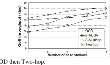
Fig. 9. Overhead versus mobility.
increases the QoS throughput of Two-hop as shown in Fig. 7.
3.2 Performance with Different Number of APs
Fig. 10 demonstrations the QoS throughput against the number of APs in the dissimilar systems. The figure demonstrations that the increase of APs clues to advanced QoS quantity in all systems. This is since more APs help to reduce path distances and physical distances between source nodes then APs, leading to inferior packet transmission than the indication power, leading to higher data transmission rate. Additional APs meaningfully reduce the lengths of initially long paths to the APs in E-AODV then S-Multihop, therefore intensely increasing their QoS throughput. In contrast, as QOD and Two-hop two-hop petite path length, their QoS throughput upsurge rate is smaller than those of S-Multihop due to the same reasons clarified in Fig. 7, E-AODV harvests less QoS throughput than S-Multihop. After the number of the APs in the system is small, the steering path lengths of S-Multihop and E-AODV are longer than those of
QOD then Two-hop.
Fig. 10. QoS throughput versus number of APs.
So, the QoS throughputs of QOD and Two-hop are superior to those of S-Multihop and E-AODV. As a result, S-Multihop crops higher QoS throughput than Two-hop. Meanwhile E-AODV also hurts from mobbing on the nodes close to the APs then its average path length is larger than Two-hop, its QoS quantity is less than Twohop. As QOD can efficiently schedule the channel capitals around the source node for packet forwarding, its QoS throughput leftovers constantly the highest.
3.3 Performance with Different Workloads
Figs. 11a and 11b conspiracy the QoS throughput of the systems by different number of basis nodes when the average node flexibility is 0 and 20 m/s, respectively. Apiece node’s mobility speed is arbitrarily chosen after the range 0 m/s to the regular mobility. Additional source nodes generate additional workload in the system. We see after both figures that as the quantity of source
nodes increases after 0 to 3, the QoS presentation of QOD increases virtually linearly.
The figure also demonstrations that Two-hop consumes less QoS throughput upsurge rate than S-Multihop as the quantity of source nodes increases. In Two-hop, the packets remain always forwarded to the nodes by higher broadcast link rate. Without any buffer organization strategy, the nodes with advanced transmission links are very effortlessly overloaded as the workload in the system upsurges. It is very fascinating to see, as the number of source nodes increases, E-AODV’s QoS throughput upsurges originally but decreases advanced. This is since in E-AODV, once the workload of the system increases, the likelihood that two or more source nodes concurrently reserve the same resources at a node increases due to the race disorder problem. Also, the nodes close to the APs are more likely to be overfilled as E-AODV does not have a resource scheduling instrument. So, the QoS throughput of E-AODV decreases in a extremely loaded system. Likening Figs. 11a and 11b, we can find that the increasing flexibility of the nodes in the system leads to a reduction of QoS throughput of all protocols. The motive is the same as in Fig. 7.
Fig. 12. QoS throughput versus network size and node mobility.
3.4 Performance with Different Network Sizes
nodes in the system, which leads to an cumulative number of neighbors of a node, enabling it to have additional available capitals for packet traffic scheduling. As the Two-hop continuously lets the source node forward the packets to the next hop node by high link rate deprived of any reserve scheduling as used in QOD, the basis nodes cannot take advantage of those increased resource nodes
everywhere themselves as the number of bulges in the system upsurges, leading to constant QoS throughput.
Comparing Figs. 12a and 12b, we understand that as the mobility of the nodes increases since 0 to 20 m/s, the QoS throughput of E-AODV then S-Multihop reductions more meaningfully as the network size upsurges. Aimed at QOD and Two-hop, the increase of flexibility does not touch their QoS throughput meaningfully because of their mobility-resilience due to short trails. More details of the reasons are obtainable as in Fig. 7.
The figure likewise shows that in QOD, a system through a larger number of bulges and source nodes has higher throughput increasing proportion. Furthermore, as the number of basis nodes in the system increases, its QoS throughput exhibitions dramatic decrease. This is caused by two reasons: 1) a large number of source nodes crop a high workload in the system, subsequent in a high likelihood of race contention and link failure, and 2) a larger number of nodes generate more transmission hops, subsequent in a high probability of connection breakdown.
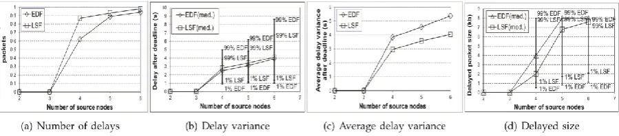
3.5 Comparison of EDF and LSF
Now this section, we associate EDF with LSF for packet advancing scheduling in QOD. We let the forwarding nodes obtain as many packets from neighbor nodes as likely without fee control to show the performance of EDF then LSF when the packets remain scheduling infeasible. In each trial, during 50 s, we continually selected a certain number of chance nodes to convey packets to their arbitrarily selected termini for a time period arbitrarily chosen from [1 to 5]s. The link rate after source nodes to relay nodes and after relay nodes to BSs was set to 2 m/s. A forwarding node calculates the limit and slack time every 1 ms.
Fig. 13a shows the fraction of the late packets of EDF and LSF. Once there are two or three source bulges, all packets are scheduling possible, thus there is no late packet in both EDF then LSF. As the number of source nodes in the system upsurges, the percentage of the late packets increases. This is since as more packets are produced, every packet in the preparation queue needs to delay for more time
to be advanced out, which leads to higher delay and hence additional delayed packets.
Fig. 13b demonstrations the first percentile, middle, and 99th percentile of the interruption after deadline of LSF and EDF. We see that EDF has inferior first percentile delay then higher 99th percentile delay than LSF, i.e., EDF has a better variance than LSF. This is since EDF forwards the packets with the initial deadlines but meaningfully delays the packets with the furthest deadlines. LSF continuously tries to
Fig. 14. QoS throughput versus number of source nodes.
Balance the delay amid different packets, consequently it consumes much lesser delay variance than EDF. This result is also established by Fig. 13c, which demonstrations that the regular delay alteration of EDF is higher than that of LSF.
3.6 Trace-Driven Experiments
Now this section, we evaluate the presentation of QOD using a additional realistic humanoid mobility model founded on the trace data set after the MIT Reality removal project involving 94 students then staffs at MIT. We used the annals of the influences with cellular barbicans in the actual trace to conclude each node’s mobility aimed at the simulation. We too used six APs that are consistently dispersed in the system in this imitation. All other formats are the similar as in Section 6. Fig. 14 displays the QoS throughput against the number of source nodes. We see that the QoS throughput shadows
Multihop>Two-hop>E-AODV. Too, unlike others that crop more QoS throughput by more source nodes, E-AODV’s QoS throughput reductions when the number of basis nodes is more than 3. The details for these results remain the same as in Fig. 11.
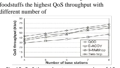
Fig. 15 shows the QoS measure versus different number of APs. We can see that QOD still foodstuffs the highest QoS throughput with different number of
Fig. 15. QoS throughput versus number of APs.
APs, which is followed by Two-hop and S-Multihop, and E-AODV produces the least amount of QoS throughput. The details for the results are the same as in Fig. 10. Likening Figs. 15 and 10, we find that the QoS quantities of QOD, S-Multihop, and Two-hop in Fig. 15 are inferior than those in Fig. 10. This is also because the community gathering property reduces the channel consumption of each node due to the intrusion between nodes inside a community.
3.7 Evaluation of TRE Based Transmission
In this section, we assess the performance of QOD-TRE using a actual Internet traffic trace we took from an access link after a large university in China to the mainstay. We still cast-off the MIT trace as the flexibility trace. The Internet trace is 120 s long and comprises 1.9 GB HTTP traffic
Fig. 16. QoS throughput versus network size and workload.
between 8,277 host pairs. We secondhand the Internet hint to pretend the web access actions of the mobile nodes in the hybrid network. The cache size of each mobile node then AP was set to 250 KB and 100 MB, correspondingly. The signature of a hunk is 32 bytes. Here are about 5 percent joblessness data in the trace after being parsed with the TRE algorithm [38].
Fig. 17. QoS throughput versus number of source nodes
Fig. 18. QoS throughput versus network size.
Figs. 17 and 18 show the QoS throughput against the number of source nodes and the number of nodes, individually. We understand as the number of basis nodes or the network size increases, the QoS quantity of both QoD and QOD-TRE increases. We can too see that the system with advanced node mobility has less throughput. The details are the same as in Figs. 14 and 16. We can also understand that the QoS throughput of QOD-TRE is consistently superior than the QoS throughput of QOD in both figures.
4 RELATED WORK
4.1 Infrastructure Networks
Existing approaches for providing certain services in the substructure networks are based on two models: combined services (IntServ) [10] and distinguished service (DiffServ). IntServ is a stateful model that uses reserve reservation for separate flow, and uses fee control [10] and a scheduler to uphold the QoS of traffic flows. In contrast, DiffServ is a nationless model which uses coarse-grained class-based instrument for traffic organization. A number of queuing preparation algorithms have been future for DiffServ to further minimalize packet droppings and bandwidth ingesting. Stoica et al. future a dynamic packet service (DPS) model to deliver unicast IntServ-guaranteed service and Diffservlike scalability.
4.2 MANETs
standby the capitals from the nodes with advanced link stability to decrease the effects of node mobility.
Some works reflect providing multipath routing to upsurge the heftiness of QoS routing. Conti et al. [16] proposed to use bulges’ local knowledge to estimation the reliability of steering paths then select reliable routes. The everything in [17] and [18] balance traffic load among manifold routes to increase routing dependability. Shen et al. [19] proposed to let a foundation node fetch the lost packets from its neighbors to recuperate the multicast traffic. Shen and Thomas [21] proposed a united mechanism to maximize both the QoS and safety of the routing. Li et al. [22] proposed a central algorithm to enhance the QoS performance by seeing cross-layer design among the bodily layer, MAC layer, and network coating.
4.3 Wireless Sensor Networks ( WSNs )
RAP [52] and SPEED [53] give a high bringing importance to the packets with lengthier distance/delay to the terminus. Though, both methods need each instrument to know its individual location, so they are not suitable for a extremely dynamic situation. Felemban et al. [54] and Deb et al. [55] proposed to recover routing reliability by multipath routing. However, the fired transmission of the packets may lead to high influence ingesting.
4.4 Hybrid Wireless Networks
Actual few methods have been future to provide QoSguaranteed routing for mixture networks. Most of the steering protocols [23], [24] only try to recover the network size and dependability to indirectly deliver QoS service then bypass the restraints in QoS routing that require the etiquettes to provide certain service. Jiang et al.Proposed a reserve delivery method in cross networks modeled by IEEE802.16e and moveable WiMax to provide service with high dependability. Ibrahim et al. [23] and Bletasa et al. [24] also strained to select “best” relay that has the maximum prompt value of a metric which can attain higher bandwidth efficiency for data broadcast. Lee et al. [58] presented a outline of link capacity analysis for best transmission over uplink transmission in multihop cellular networks. Wei et al. proposed a two-hop packet forwarding device, in which the source node adaptively chooses direct transmission and forward transmission to base stations. Unlike the above works, QOD aims to provide QoSguaranteed routing. QOD fully takes benefit of the widely organized APs, and novelly treats the packet routing problem as a reserve scheduling problem amid nodes and APs.
5 CONCLUSIONS
Hybrid wireless networks that mix MANETs and substructure wireless networks have established to be a better network construction for the next cohort networks. But, little effort has been devoted to supporting QoS steering in hybrid networks. Direct adoption of the QoS routing methods in MANETs into mixture networks inherits their problems. In this paper, we propose a QoSoriented distributed routing protocol (QOD) for hybrid networks to provide QoS services in a extremely dynamic scenario. Taking advantage of the exclusive features of hybrid systems, i.e., anycast transmission and short transmission hops, QOD transforms the packet routing problem to a packet preparation problem. In QOD, a source node directly conveys packets to an AP if the direct transmission can assurance the QoS of the traffic. Then, the source node schedules the packets to a number of capable neighbor nodes. Exactly, QOD incorporates five procedures. The QoS-guaranteed neighbor selection algorithm chooses capable neighbors for packet forwarding. The dispersed packet scheduling procedure schedules the packet broadcast to further reduce the packet broadcast time. The mobility-based packet resizing algorithm resizes packets and assigns smaller packets to nodes with earlier mobility to guarantee the routing QoS in a highly mobile setting. The traffic fired elimination-based transmission algorithm can further increase the transmission throughput. The soft-deadline-based advancing scheduling attains fairness in packet forwarding scheduling once some packets are not preparation feasible. New results show that QOD can attain high mobility-resilience, scalability, and contention reduction. In the upcoming, we plan to assess the presentation of QOD based on the real test bed.
ACKNOWLEDGMENTS
This work was supported in part by the US National Science Foundation under grants OCI-1064230, 1249603, CNS1049947, CNS-1156875, CNS-0917056, CNS-1057530, CNS1025652, CNS-0938189, CSR-2008826, and CSR-2008827, Microsoft Research Faculty Fellowship 8300751, and the US Department of Energy’s Oak Ridge National Laboratory including the Extreme Scale Systems Center located at ORNL and DoD 4000111689. An early version of this work was presented in the Proceedings of MASS ’10 [59].
R
EFERENCES[1] “A Majority of U.S. Mobile Users Are Now Smartphone
Users,” http://adage.com/article/digital/a-majority-u-s-mobile-userssmartphone-users/241717, 2013.
[2] Qik, http://qik.com, 2013.
[4] Facebook, http://www.facebook.com, 2013.
[5] H. Wu and X. Jia, “QoS Multicast Routing by Using Multiple
Paths/Trees in Wireless Ad Hoc Networks,” Ad Hoc Networks, vol. 5, pp. 600-612, 2009.
[6] H. Luo, R. Ramjeey, P. Sinhaz, L. Liy, and S. Lu, “UCAN: A
Unified Cell and Ad-Hoc Network Architecture,” Proc. ACM MobiCom, 2003.
[7] P.K. Mckinley, H. Xu, A. Esfahanian, and L.M. Ni,
“Unicast-Based Multicast Communication in Wormhole-Routed Direct Networks,” IEEE Trans. Parallel Data and Distributed Systems, vol. 5 , no. 12, pp. 1252-1265, Dec. 1992.
[8] H. Wu, C. Qiao, S. De, and O. Tonguz, “Integrated Cell and Ad
Hoc Relaying Systems: iCAR,” IEEE J. Selected Areas in Comm., vol. 19, no. 10, pp. 2105-2115, Oct. 2001.
[9] J. Zhou and Y.R. Yang, “PAR CelS: Pervasive Ad-Hoc
Relaying for Cell Systems,” Proc. IFIP Mediterranean Ad Hoc Networking Workshop (Med-Hoc-Net), 2002.
[10] R. Braden, D. Clark, and S. Shenker, Integrated Services in the
Internet Architecture: An Overview, IETF RFC 1633, 1994.
[11] E. Crawley, R. Nair, B. Rajagopalan, and H. Sandick, Resource
Reservation Protocol RSVP, IETF RFC 2205, 1998.
[12] I. Jawhar and J. Wu, “Quality of Service Routing in Mobile Ad
Hoc Networks,” Network Theory and Applications, Springer, 2004.
[13] T. Reddy, I. Karthigeyan, B. Manoj, and C. Murthy, “Quality of
Service Provisioning in Ad Hoc Wireless Networks: A Survey of Issues and Solutions,” Ad Hoc Networks, vol. 4, no. 1, pp. 83-124 , 2006.
[14] X. Du, “QoS Routing Based on Multi-Class Nodes for Mobile
Ad Hoc Networks,” Ad Hoc Networks, vol. 2, pp. 241-254, 2004.
[15] S. Jiang, Y. Liu, Y. Jiang, and Q. Yin, “Provisioning of
Adaptability to Variable Topologies for Routing Schemes in MANETs,” IEEE J. Selected Areas in Comm., vol. 22, no. 7 , pp. 1347-1356, Sept. 2004.
[16] M. Conti, E. Gregori, and G. Maselli, “Reliable and Efficient Forwarding in Ad Hoc Networks,” Ad Hoc Networks, vol. 4 , pp. 398-415, 2006.
[17] G. Chakrabarti and S. Kulkarni, “Load Balancing and Resource
Reservation in Mobile Ad Hoc Networks,” Ad Hoc Networks, vol. 4 , pp. 186-203, 2006.
[18] A. Argyriou and V. Madisetti, “Using a New Protocol to
Enhance Path Reliability and Realize Load Balancing in Mobile Ad Hoc Networks,” Ad Hoc Networks, vol. 4, pp. 60-74, 2006.
[19] C. Shen and S. Rajagopalan, “Protocol-Independent Multicast
Packet Delivery Improvement Service for Mobile Ad Hoc Networks,” Ad Hoc Networks, vol. 5, pp. 210-227, 2007. [20] C.E. Perkins, E.M. Royer, and S.R. Das, Quality of Service in
Ad Hoc On-Demand Distance Vector Routing, IETF Internet draft, 2001.
[21] Z. Shen and J.P. Thomas, “Security and QoS Self-Optimization
in Mobile Ad Hoc Networks,” IEEE Trans. Mobile Computing, vol. 7 , pp. 1138-1151, Sept. 2008.
[22] Y. Li and A. Ephremides, “A Joint Scheduling Power Control
and Routing Algorithm for Ad Hoc Networks,” Ad Hoc Networks, 2008.
[23] S. Ibrahim, K. Sadek, W. Su, and R. Liu, “Cooperative
Communications with Relay-Selection: When to Cooperate and Whom to Cooperate With?” IEEE Trans. Wireless Comm., vol. 7, no. 7 , pp. 2814-2827, July 2008.
[24] A. Bletsas, A. Khisti, D.P. Reed, and A. Lippman, “A Simple Cooperative Diversity Method Based on Network Path Selection,” IEEE J. Selected Areas in Comm., vol. 24, no. 3, pp. 659-672, Mar. 2006.
[25] T. Ng and W. Yu, “Joint Optimization of Relay Strategies and