Volume 16, Number 4, pp. 333–354. http://www.scpe.org
ISSN 1895-1767 c
⃝2015 SCPE
COMBINING POSOMAS METHOD CONTENT WITH SCRUM: AGILE SOFTWARE ENGINEERING FOR OPEN SELF-ORGANISING SYSTEMS
JAN-PHILIPP STEGH ¨OFER∗AND HELLA SEEBACH, BENEDIKT EBERHARDINGER, MICHAEL H ¨UBSCHMANN, WOLFGANG REIF†
Abstract. In this paper we discuss how to combine the method content from PosoMAS, the Process for open, self-organising Multi-Agent Systems, with the agile iterative-incremental life cycle of Scrum. The result is an agile software engineering methodology tailored to open self-organising systems. We show how the methodology has been applied in a development project and discuss the lessons learned. Finally, we compare the Scrum version of PosoMAS to other agile agent-oriented software engineering methodologies and address the selection of a suitable process.
Key words: Agent-oriented Software Engineering, Self-Organising Systems, Software Engineering Processes
AMS subject classifications. 68T42, 68N30
1. Challenges of Agent-oriented Software Engineering Processes. The fact that multi-agent sys-tems (MAS) and self-organisation have not yet arrived in the software engineering mainstream is a pity, especially since the potential of these technologies with regard to robustness, adaptivity, and scalability has been demon-strated (see, e.g., [22, 27, 28]). There are a number of reasons for this situation, not the least of which is that discussion on these topics takes place mostly in academia and very rarely involves actual software companies. Another reason might be that there is a plethora of approaches, often requiring specialised modelling tools and languages, and in general ways of thinking about the systems under construction different from “traditional” software engineering, or depending on a certain runtime infrastructure.
Interestingly, these “traditional” processes make no or very little assumption about which kind of software is developed with them. They are agnostic of the framework used, the tool, modelling languages, programming paradigm, and deployment platform. A process like OpenUP [20] is just as useful in building a game for an Android phone than it is for building a scientific application. Arguably, this agnosticism is possible due to the fact that the guidance provided by these processes is on such an abstract level. It also considers the management of the project much more than the actual technical execution. On the other hand, these processes had a long time to mature and grow with constant feedback from industry and academia.
Agent-oriented methodologies in general follow a different philosophy: instead of focusing on issues of project management and providing structure for the different technical activities, they describe the way to a technical solution in great detail. They are thus much more specific to the domain and often to a certain architecture, tool, or framework. Of course, this takes a lot of the guesswork out of building a multi-agent system and especially allows inexperienced developers to come up with a solution that uses the somewhat unique or at least unusual paradigm for a developer familiar with object-oriented programming.
While this philosophy doubtlessly has its merits, it also prevents using the method content developed in the different approaches to be interchanged and hinders the tailoring of the processes. If we look at the method content of INGENIAS [18] or ASPECS [10], e.g., we can see that many of the activities are specific to the meta-model used and are not compatible with other processes using no or a different meta-model. This is arguably an impediment to cross-fertilisation and convergence towards common standards in the community.
PosoMAS has adopted a different philosophy. As outlined in our previous paper on the process [40] and in Sect. 2, it has been created to respond to a number of requirements, including extensibility and customisability as well as independence from architectures or tools. By following the example of OpenUP and defining independent practices, the method content is highly adaptable, amenable to tailoring, and can be re-used in different contexts. We therefore consider PosoMAS to be more of a collection of reusable assets than a process in and of itself.
∗Chalmers Technical University — University of Gothenburg, Software Engineering Division, Gothenburg, Sweden (
†Augsburg University, Institute for Software & Systems Engineering, Augsburg, Germany ({firstname.
lastname}@informatik.uni-augsburg.de,[email protected])
The management aspects of the process are provided by a framework process and lifecycle. In this regard, PosoMAS has similarities to O-MaSE [14] but does not enforce the use of a specific tool for process tailoring and modelling.
At the same time, PosoMAS’ technical practices address the needs of a specific subset of MAS that have so far been somewhat neglected. If a system has to be open and has to exhibit self-organisation, principled software engineering techniques become even more important. For instance, in such cases, the benevolence assumption, i.e., the assumption that the individual agents contribute to reaching an overall system goal, can no longer be maintained. The dynamics of self-organisation and the potential negative emergent effects are thus coupled with self-interested, erratic, and even potentially malevolent agents that still have to be integrated in the system. Examples for domains that exhibit such effects are energy management [41] and open grid computing [6]. Arguably, some of the practices dealing with the specifics of the system class introduce specific modelling elements or suggest certain notation — but by no means is the developer forced to adopt these practices or to comply to a meta-model for the entire project.
Our previous scientific contributions (refer to, e.g., [41, 43, 17, 42]) have dealt with these issues without being embedded in a methodology for the principled design of such systems. While conceptual and algorithmic solutions for such problems are often the focus of research, they are rarely embedded in a methodology for the principled design of such systems, a shortcoming that we aim to remedy with the PosoMAS method content.
This paper combines the method content of PosoMAS with the project management practices of Scrum and the Agile System Development life-cycle (SDLC) that embeds Scrum sprints in an iterative framework. It introduces the requirements that motivate the development of PosoMAS (Sect. 2), outlines the most important practices of PosoMAS (Sect. 3), shows how they are embedded in the life cycle (Sect. 4) and demonstrates the way the resulting process can be applied in the development of a MAS (Sect. 5). We also put our work in the context of other agent-oriented software engineering approaches and in particular compare the PosoMAS method content and its application to Scrum with Prometheus [32], ASPECS, and with the Scrum version of INGENIAS in Sect. 6. Finally, we discuss benefits, limitations, and lessons learned in our development efforts (Sect. 7).
The present work extends our previous paper on PosoMAS [40] in several ways: it offers a guideline of how the method content can be combined with different life cycles and project management styles based on situational method engineering and exemplifies the guideline with Scrum; it provides an example showing how the process can be applied in practice; and it discusses the similarities and differences with INGENIAS-Scrum, a process that has not been part of the analysis before. Since the format of a research paper is insufficient to describe a comprehensive methodology in full detail, the reader is advised to peruse the detailed process description at http://posomas.isse.de. The website also offers the method content for use in the EPF Composer and additional information on the comparison of AOSE processes.
2. Requirements for a Process for Large-Scale Open Self-Organising Systems. There are two
main themes that define the requirements we have identified for the design of PosoMAS: the ability to use the method as readily as standard object-oriented methodologies and the ability to deal with characteristics of open self-organising systems. The individual requirements listed below address those themes and are the basis for the solution that has been developed. The first four requirements address the need to create an open, flexible, and extensible process. As discussed in Sect. 1 and 6, other MAS methodologies lack this flexibility at this point. The requirements listed here are the result of an analysis of existing agent-oriented software engineering approaches and reflections of our own experience with processes and engineering of self-organising system (see, e.g., [38, 43]). While they have guided the development of PosoMAS, we consider them work in progress. As we gain more experience and confidence in applying the process, we expect to understand the needs better and consequently refine these requirements.
thus standard modelling tools. It also means that the process has to be as adaptable and customisable as methodologies used for object-oriented software engineering.
R2: Architecture and tool agnostic The internal architecture of the agents (such as BDI) should play as little role in the high-level design part of the process as the implementation platform on which the agent system will run. Object-oriented methodologies such as OpenUP or the V-Model are defined on a level of abstraction that enables this agnosticism. The methodology should be applicable regardless of the concrete architecture and implementation platform used to allow applicability to a wide array of scenarios.
R3: Level of detail. The process must contain support for all relevant activities in the design process. It must make clear which knowledge it assumes the designer to have and point to additional material that can be used to extend the level of understanding. The methodology must contain sufficient guidance and templates for the artefacts that must be created. The methodology should also cover the entire life cycle of a software engineering methodology, including deployment of the system.
R4: Extensibility and customisability. The methodology must be extendible and it must be possible to combine it with different process models and to customise it for specific situations as part of a situational method engineering process. This means that it must be possible to use the method chunks put forward in an agile context (e.g., by using it in a specialised Scrum process as described in this paper) as well as in a heavy-weight context (e.g., using the still pervasive waterfall method), or to embed it in the risk/value life cycle provided by the OpenUP (as described in [40]). It must also be possible to apply situational method engineering [21] to the process to come up with a methodology suitable for the project, the team, and the environment it will be used in.
The second set of requirements deals more directly with the needs present in open self-organising systems and address their openness, their scale, and the aspect of self-organisation.
R5: Clear separation of different architecture domains. Especially in open systems, development of the individual agents might not be in the hand of the system designer. In the example of an autonomous power grid [41], the agents representing the power plants are not designed by the same people that design their interaction in the system and set up the infrastructure. Instead, the system designer has to define interfaces, data models, and interactions so that other development teams know how the agents should behave in the system, interact with other agents, and with the system as a whole. Even if the system and the individual agents are implemented by the same company, different teams within the organisation can be responsible for the implementations.
R6: Special focus on interactions between agents and agent organisations. The dynamics of an open self-organising multi-agent system are defined by the interactions between agents within organisations under uncertainty. The behaviour of the individual agent within an organisation plays an important role for the fitness for purpose of the organisation and of its ability to reach its goal within the system. Organisations and their structure also play an important role in terms of the scalability of the final system. Different system structures of organisations—among them hierarchical ones—must be supported by the design activities as well as requirements elicitation and analysis.
R7: Top-down design vs. bottom-up functionality. While a systems engineering methodology is necessarily top-down, starting from overall system goals, self-organisation processes and coordinated processes within multi-agent systems provide this striven for functionality in a bottom-up way [43]. A methodology that is suitable for self-organising systems must take this change of perspective into account and provide appropriate tools for the design, test, and implementation of bottom-up processes.
In addition to these requirements, we adopt the principles of standard software engineering methods such as OpenUP, that promote reuse, evolutionary design, shared vision, and others. These principles are documented, e.g., in [25] for the Rational Unified Process, a commercial software engineering methodology that introduced many of the features that are present in modern processes such as OpenUP.
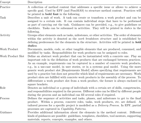
Table 3.1: Simplified description of important process modelling concepts.
Concept Description
Practice A collection of method content that addresses a specific issue or allows to achieve a
specific goal. Used by EPF (and PosoMAS) to structure method content. Practices will
be printed inbold fontin the following.
Task Describes a unit of work. A task can create or transform a work product and can be
assigned to a certain role. It can contain individual steps that have to be performed as part of carrying out the task. Guidances can be provided, e.g., to give guidelines or
checklists. Tasks can be subsumed in activities. They will be printed in italics in the
following.
Activity Groups other elements such as tasks, milestones, or other activities. The order of elements
within the activity is denoted as the work breakdown structure and is established by
defining predecessors for the elements in the structure. Activities will be printed inbold
italics.
Work Product Documents, models, code, or other tangible elements that are produced, consumed, and
modified by tasks. Responsibilities for work products can be assigned to roles.
Work Product Slot Define an abstract work product that can be instantiated with a concrete one. Play an
important role in the definition of work products that are exchanged between practices. As an example, requirements can be captured in a number of concrete work products, e.g., in a use-case model, in user stories, or in a systems goal model. Using the more generic work product slot [Requirements Model] allows specifying that requirements are used by a practice but does not prescribe which kind of requirements are necessary. Work product slots are fulfilled with concrete work products in the assembly of the process. To differentiate a work product slot from a work product, the former is always enclosed in square brackets.
Role Denotes an individual or a group of individuals with a certain set of skills, competencies,
and responsibilities required in the process. Different roles can be filled by different people during the process and an individual can fill several roles if required.
Process Defines the sequence of activities and tasks, phases, and milestones to get to the final
product. Within a process, concrete roles, tasks, work products, etc. are defined. A
tailored process for a specific project is modelled as a Delivery Process. In EPF, partial
processes are captured in Capability Patterns.
Guidance Provides additional information about the elements in the method content. Different
kinds of guidances are possible: guidelines, templates, checklists, tool mentors, supporting materials, reports, concepts, examples, and others.
as of yet. It is possible, however, to use practices from other processes for these issues as illustrated in Sect. 4.2.
All PosoMAS method content is specified using SPEM1. The most important SPEM concepts used in the
following are detailed in Table 3.1. Furthermore, PosoMAS makes use of EPF2. EPF provides a common
baseline for process development by providing a usable version of SPEM as well as a tool to define processes, the EPF Composer. In addition, it provides process content in the form of method libraries, such as a model of OpenUP. The EPF method libraries introduce a number of commonly used concepts, such as pre-defined roles for developers and architects. PosoMAS makes use of these common concepts instead of re-defining them, extends them if necessary and adds many specific elements that are not covered in the standard libraries.
1
Software & Systems Process Engineering Metamodel (http://www.omg.org/spec/SPEM/2.0/), defined by the Object Manage-ment Group (OMG).
2
3.1. Rationale and Structure of PosoMAS. We adopt the notion of situational method engineer-ing [21]: while we define method content (i.e., tasks, activities, work products, guidance, etc.) and in some aspect also the order in which this method content should be applied, the content is formulated in such a way that a process engineer can use it to construct a specific instance of a process tailored to the development effort
at hand. This means that the method content (collected inpractices that address specific needs and purposes)
is combined with a specific life cycle and selections are made, how the content is used, who is going to fill the roles, and which work products are created and used. The creation of a specific process instance from existing
method content is known as process tailoring. Allowing this flexibility and adaptability addresses requirement
R4: Extensibility and customisability.
The practices that contain the method content in PosoMAS introduce techniques for the principled de-sign of individual agents, organisations, their interactions, as well as the overall system and the environment. The categorisation of these techniques is an important aspect of the design of the process and addresses the requirement for R5: Clear separation of different architecture domains:
Agent Architecture: the design of the individual agents, separate for each type of agent relevant in the system.
Agent Organisation: the specification of organisational paradigms that will structure the agent population at runtime.
Agent Interaction: the definition ofinterfaces and protocolsused by agents to exchange information, delegate control, and change their organisational structure.
System Architecture: the design of theentire system, including the relationship between the different types of agents, the supporting infrastructure, and external components as well as the environment.
The PosoMAS method content is connected by the use of work product slots to exchange information between the activities and tasks specified for each practice. As an example for exchange within PosoMAS,
consider Practice: Agent Environment Design. It contains tasks that describe how a work product slot
[Requirements Model] is used as the basis for identification of the necessary infrastructure to support the MAS under construction (e.g., external services that must be used, relevant actors that require an interface to the system). The identified infrastructure, which interfaces are necessary, and what these interfaces look like is captured in the Multi-Agent System Architecture work product. This work product is used by other practices,
such asPractice: Evolutionary Agent DesignorPractice: Organisational Designas an input for their
own design decisions. The flow of work products thus defines how the practices and activities within PosoMAS are connected.
These work products are also the interface to method content from other processes. INGENIAS, e.g., offers method content for the design of BDI agents. If a concrete process instance for a specific project wants to
make use of this method content, it can, e.g., use the activityGenerate Agent Model [18] from INGENIAS. This
activity creates a concrete instantiation of the work product slot [Agent Architecture], as defined in PosoMAS. Since all practices in PosoMAS are independent of the concrete instantiation of this work product slot, but rather require abstract properties (the instantiation should be a description of the internal architecture of an agent), the content from different processes can be readily combined. In this way, the work product slots act comparably to interfaces in object-oriented programming.
PosoMAS does not prescribe a specific modelling language or a certain tool chain. Instead, it suggests the use of UML and gives the developers support in that by providing a corresponding UML profile for the definition of agent concepts. This addresses R1: Accessibility to “traditional” software engineers and R2: Architecture and tool agnostic.
3.2. Overview of PosoMAS practices. As PosoMAS is targeted at open systems, the architectural
tasks are aimed at providing standardisation, separation of concerns, and interoperability. The applicability to a wide range of target systems has also been a concern. Therefore, even though some content of the practices is specific to open self-organising MAS, they do not require the use of a specific meta-model or agent architecture, again addressing R2: Architecture and tool agnostic. The concrete practices are also tailored to address R6: Special focus on interactions between agents and agent organisations, a requirement that has greatly influenced
the practicePractice: Organisational Design, and R7: Top-down design vs. bottom-up functionality which
Evolutionary Agent Design and Practice: Organisational Design. The practice library provides the
practices described briefly below. Missing from the content here is Practice: Trust-based Interaction
Design, as it has not been applied in the case study. It encompasses the design and implementation of a trust and reputation system to deal with agents for which the benevolence assumption does not hold. Please note that rather than stating the concrete outputs of the practices below, we state the work product slots that the outputs can fill, in order to show how the practices can be combined.
Practice: Goal-driven Requirements Elicitation
Description: Operationalises the technique for requirements elicitation based on KAOS [26] and the work of
Cheng et al. [9]. The purpose of this practise is to provide an iterative process to successively refine the goal model until a complete model of the system requirements is gained. Beside the system goal model, a conceptual domain model as well as a glossary of the domain are outputs of this practice. The approach is ideally suited for adaptive systems since uncertainties and their mitigation can be directly modelled in the requirements. This allows the stakeholders to reason about countermeasures and identify risks early on. The practice is easily embedded in iterative-incremental processes. System goals can be elaborated in different iterations, with a preference to elaborate those first that have the greatest potential impact and risk. Guidelines detail the application of the practice in an agile environment and how to capture process support requirements. We demonstrate in Sect. 5 how this practice can be integrated with the backlogs used in Scrum.
Main Input: Vision Document
Main Output: Requirements Model
Practice: Pattern-driven MAS Design
Description: Provides guidance to design a MAS based on existing architectural, behavioural, and
inter-action patterns and reference architectures. These three types of patterns correspond to the system architecture, agent architecture, and agent interaction areas. The practice enables reuse, avoids making mistakes twice, and allows tapping into the knowledge that has been created elsewhere for a cleaner, leaner, and more flexible design.
Main Input: [Agent Architecture], [Interaction Model], [Multi-Agent System Architecture], [Requirements
Model]
Main Output: [Agent Architecture], [Interaction Model], [Multi-Agent System Architecture], Architectural
Style Notebook
Practice: Evolutionary Agent Design
Description: Describes an approach to design agents and their architecture in an evolutionary way that
enhances the design over time while requirements become clearer and development progresses. During the development process, the agent types, their capabilities and behaviour, their in-ternal architecture, and their interactions become clearer as the requirements mature and development progresses towards a shippable build. To allow the product to mature this way, the design of the agents has to adapt to new knowledge continuously and become more specific by refinement when necessary and incorporating changes in the requirements or the system environment.
Main Input: [Requirements Model]
Practice: Agent Environment Design
Description: Outlines how the system the agents are embedded in is designed and how the agents interact
with it. This pertains to the System Architecture aspect. A MAS not only consists of
au-tonomous agents but also incorporates a multitude of additional often grounded infrastructure, external actors, interfaces, hardware, and environmental factors. These can have a significant impact on the overall system design and should be regarded early on. The practice provides tasks to identify these factors and incorporate them in the design of the overall system. This includes the identification and design of necessary interfaces between the agents and to external components in the system’s environment as well as the identification of uncertainty factors in the environment.
Main Input: [Interaction Model], [Requirements Model]
Main Output: [Multi-Agent System Architecture], [System Environment Description], [Interaction Model]
Practice: Organisational Design
Description: Describes the design of the organisation [23] the agents will interact in, thus addressing the
Agent Organisationaspect. Multi-agent systems with many interacting agents require a form of structure or organisation imposed on the population. Sometimes, this structure is permanent, such as a hierarchy that determines the delegation of control and propagation of information, or transient, such as a coalition in which agents interact until a certain common goal is reached. The system designer has to decide which organisations are suitable for the system to reach the stated goals and implement mechanisms that allow the formation of these organisational structures at runtime. If this process is driven from within the system, “self-organisation” is present.
Main Input: [Multi-Agent System Architecture], [Requirements Model]
Main Output: [Agent Organisation Definition]
Guidance: Bryan Horling and Victor Lesser – A Survey of Multi-Agent Organizational Paradigms
(Whitepaper) [23]
Practice: Model-driven Observer Synthesis
Description: Describes how observer implementations can be synthesized from constraints specified in the
requirements documents as described in [17]. In adaptive systems, it is necessary to observe the system and react if the system enters an undesirable state or shows unwanted behaviour. For this purpose, feedback loops, operationalised as observer/controllers can be employed [36]. Therefore, this practice supports the developer on the automatic transformation of specified constraints into observers that monitor these constraints at runtime. A prerequisite of this practice is that constraints have been captured during requirements analysis. The process can be repeated after the requirements or the domain model have changed, according to a model-driven design (MDD) approach. Changed parts of the system models and implementation will be re-generated while existing models and code are preserved.
Main Input: [Agent Architecture], [Interaction Model], [Multi-Agent System Architecture], [Requirements
Model]
Main Output: Observation Model, Implementation
Guidance: How to adopt the Model-driven Observer Synthesis practice (Roadmap), Observation Model
(Concept), Observer/Controller Architecture (Concept), Benedikt Eberhardinger et al. –
Model-driven Synthesis of Monitoring Infrastructure for Reliable Adaptive Multi-Agent Sys-tems (Whitepaper) [17]
takes one or several work products (or work product slots) as inputs and outputs.
For use within a process, tasks from different practices are combined in activities. These activities are often addressing a common theme. For PosoMAS-Scrum, e.g., the activity Develop Agent Architecture combines tasks
fromPractice: Pattern-driven MAS DesignandPractice: Evolutionary Agent Design. Activities and
tasks can in turn be combined in capability patterns (nested activities, so to speak) such as Design Architecture Components. These patterns are then arranged within the lifecycle as demonstrated in Sect. 4.2.
The detailed practice descriptions and the models for use in EPF are available at http://posomas.isse.de. We thus provide a repository for method content and make reusable assets available for combination with method content from other processes, fulfilling the appeal of the IEEE FIPA Design Process Documentation and Fragmentation Working Group and many authors (e.g., [39, 11]).
4. The PosoMAS-Scrum Life Cycle. The process life cycle determines the progression of a product
under development in the context of the process, the stakeholders, and the environment. A well-defined life cycle provides guidance w.r.t. the order of activities the Scrum Team has to perform, the project milestones and deliverables, and the progress of the product. The advancement of a product development effort can thus be measured based on the planned and the actual progress within the life cycle. Scrum is an example of a light-weight process framework that embraces the Agile Manifesto [5]. It consists of a number of rules that
prescribe how roles, events, and artefacts have to be combined for aScrum Teamto manage a complex software
development project and create value for the customer [37]. Within these boundaries it is possible to apply
custom development practices. Scrum has been modelled in the EPF Composer by Mountain Goat Software3
and a method plugin containing the method content is available. The customisation is based on a significant extension of this method content.
4.1. Structure of Scrum. At the core of Scrum is the insight that it is impossible to conclusively define requirements and that it is therefore necessary to include the client in all phases of the development and be able to react to changes in the requirements quickly. A change request is thus not an exceptional event but something rather normal, making it very easy to incorporate changes into the development process. The decisions of the
project team are always based on what is currently known about the project, a principle calledempiricism [37].
This makes it necessary to form decisions transparent for the stakeholders, inspect past decisions based on new data regularly, and adapt if the circumstances have changed.
The other principle is the focus on a self-organising Scrum Team. While different roles still exist, Scrum promotes the notion that different members of the Scrum Team assume these roles of their own accord. The Scrum Team decides internally how the work is split among the team members and is involved in all important
decisions, including assessment of the effort required to perform certain tasks. A Scrum Master is designated
in each team who ensures that the Scrum rules are adhered to, but also acts as a spokesperson for the Scrum
Team and coordinates communication with external stakeholders. Importantly, a Product Owner, ideally a
representative of the client with the authority to make decisions about the product and embedded in the Scrum Team, defines the requirements and prioritises them by importance. She is also available to the Scrum Team to answer questions and relay issues that come up during development to the client organisations. The Product Owner has, however, no authority over the Scrum Team [37].
The most important communication device between the Scrum Team and the Product Owner is theProduct
Backlog. It contains all currently known and open requirements for the product, including features and non-functional requirements [37]. While Scrum does not prescribe the form in which requirements are represented in
the product backlog, they are often captured in the form ofuser stories (see, e.g., [31]). A user story describes
who wants to achieve what and why. Regardless of the form the requirements take, they are ordered in the
backlog according to their risk, customer value, complexity, or any other criteria the Product Owner deems reasonable.
The Scrum Team estimates the effort required to realise the requirements. As part of a “grooming” process, the Product Owner and the Scrum Team together refine the requirements, re-order them and adapt estimates.
As part of aSprint Planning Meeting, the requirements that will be tackled in the next development iteration —
3
Potentially Shippable Product Increment
Sprint Finalisation Sprint
Planning
Daily Work
Sprint 2 to 4 Weeks Daily Scrum
Initial Requirements
Sprint Backlog
Product Backlog
Highest Priority Work Items
Release to Production Defect Reports and
Change Requests
Enhancement and Change Requests
Construction Iterations
Working System
Fig. 4.1: Ambler et al.’s Agile System Development life-cycle (SDLC) [3] as used for PosoMAS-Scrum. SDLC is an extension of the standard Scrum sprint life cycle with iterations and consideration of preparatory as well
as release activities. Initial requirements are captured in a Product Backlog. An iteration consists of Sprint
Planning, in which the backlog is prioritised and the work items for the sprint are selected. The sprint itself
consists of small increments of Daily Work, initiated by a Daily Scrum. After the 2 to 4 weeks of the sprint
are completed, aPotentially Shippable Product Incrementhas been created. TheSprint Review, which together
with the Sprint Retrospective constitutes the Sprint Finalisation, gives all stakeholders the opportunity for
feedback. After construction is complete, the working system is released to production. The product backlog can be changed or augmented by the stakeholders at any time during or after a sprint.
called aSprint— are picked and transferred into theSprint Backlog. During the sprint, the Scrum Team creates
a completePotentially Shippable Product Increment that realises the picked requirements (theSprint Goal) over
a time horizon of a month. The Product Owner can cancel the sprint if the Sprint Goal no longer aligns with the client organisation goals.
During a sprint, daily structured meetings are performed to further communicate between the Scrum Team
members and to assess the progress of the sprint. These Daily Scrums—also called Standup Meetings since
they are usually held with all participants standing—are 15-minute meetings in which the progress, the planned
work, and any issues are discussed [37]. In larger projects, aScrum of Scrums can be used with similar rules to
coordinate between different Scrum Teams. Scrum promotes co-location of all team-members, meaning that it is easy to communicate directly with other members of the team, to exchange information, and to help each other with technical difficulties. When the sprint is concluded, the Scrum Team presents the Potentially Shippable
Product Increment to the Product Owner during the Sprint Review and fulfilment of the Sprint Goal as well
as future requirements and necessary changes are discussed. Finally, the Sprint Retrospective gives the Scrum
Team a chance to reflect on the last sprint and discuss possible improvements.
4.2. Embedding PosoMAS practices in Scrum. The description above does not include concrete
Sprint Planning Sprint Sprint Finalisation
Estimate the product backlog
Prioritizing the product backlog
Estimate Velocity
Sprint Planning Meeting
Task Breakdown
Sprint Review Meeting
Sprint Retrospective Daily Scrum
Clarify Requirements
Update the product backlog
Define Agent Organisations
Design Architecture Components Design System
Dynamics
Develop Solution Increment
Develop Trust-Based Interactions
Specify Agent Interactions
Prepare Potentially Shippable Build
Prepare Sprint Review
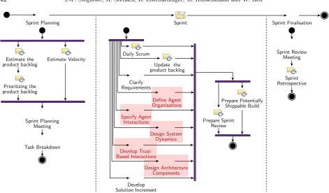
Fig. 4.2: Structure of an iteration in PosoMAS-Scrum, combining method content from PosoMAS, Scrum, and OpenUP. An iteration is started by preparatory activities to produce a new version of the product backlog and select requirements for the sprint. During the sprint, the activities from PosoMAS (highlighted) are performed as required during the daily work. The sprint ends after a certain time or when all backlog items have been tackled with a Sprint Review and a Sprint Retrospective.
a Scrum Team can decide to create less models or combine models suggested by PosoMAS activities and tasks. Since most of the management documents have been defined in the OpenUP and are not present in the PosoMAS-Scrum method configuration, no additional customisation has to be performed in this regard.
PosoMAS adds most of its method content in the design activities and replaces use cases with system goals as the main model to capture requirements. Therefore, PosoMAS-Scrum has requirements engineering activities in parallel to the ongoing development work, performed mostly by the Product Owner. The Scrum Team estimates requirements whenever necessary. The sprint backlog that contains those requirements that will be tackled in a sprint is created from the Product Backlog during the Sprint Planning Meeting. Initial
requirements are captured in the release planning stage, before the sprints are begun, a task similar to theInitiate
Project activity described for the OpenUP earlier [40]. The product backlog is refined by new requirements that are created during sprints or come up during the Sprint Review. PosoMAS-Scrum does not prescribe the way requirements are captured and the example in the next section shows how goal-oriented requirements engineering can be used in this context. This is an example of process tailoring where the generic process has been adapted to suit the needs of the development effort.
PosoMAS-Scrum also encompasses activities to prepare the release of the product. For this purpose, method
content from the OpenUP practiceProduction Releasehas been embedded at the end of the life cycle to provide
guidance for the eventual rollout of the finished product. The use of this practice from a different process also illustrates the modularity of PosoMAS and OpenUP and how their elements can be combined beneficially.
5. Sprint Example. We present how PosoMAS-Scrum is applied in a case study that shows an excerpt of
collab-oration with students applying PosoMAS-Scrum and now serves as a proving ground for new self-optimisation and self-adaptation mechanisms. In its current form, it consists of a sophisticated simulation environment with a visualisation. It is based on the Jadex multi-agent platform [34], providing a distributed implementation of the agents and an implementation of the environment the agents interact in, including a mock enterprise resource planing system.
The case study demonstrates the strengths of PosoMAS-Scrum, illustrates the interplay of Scrum manage-ment techniques and PosoMAS technical method content, exemplifies how developmanage-ment progresses in PosoMAS-Scrum, and documents the use of different process activities and tasks supporting the development. While the previous description of the practices does not go down to the task level, we have included the tasks in the description to indicate which PosoMAS method content is concretely applied.
In the following, we first introduce the vision of the system to be developed before diving into the second sprint of the development process. We then discuss briefly how Posomas-Scrum has been tailored for that specific development effort before we introduce the status of the product after the first iteration. Based on this, we detail how PosoMAS-Scrum has been applied in the second sprint.
5.1. Automated Material Handling and Order Fulfilment System. An Automated Material
Han-dling and Order Fulfilment System (AMHOFS) includes the “chaotic” storage of goods on shelves, the replen-ishment of these shelves, as well as packing parcels in “pack stations”. In the warehouse no human intervention is needed as the AMHOFS manages itself. AMHOFS are usually regarded as black boxes, i.e., the activities of the system and information such as the current place of an item or which robot does what are irrelevant to the order management system or the enterprise resource planning (ERP) system. Of course, interfaces exist so that orders generated by an ERP system are fulfilled by the AMHOFS and packed parcels are registered in the ordering system.
An AMHOFS consists of movable shelves which are transported by mobile robots to pack stations within a warehouse. Five to ten of such battery-powered robots serve one pack station to guarantee a continuous supply of shelves. At the pack station humans put goods from arriving shelves into parcels. This can be done in parallel for several parcels. The robots visit charging or repair stations from time to time. They find their path by the use of markings embedded in the ground. The control of the robots is mainly performed by a central dispatch server which registers obstacles and accordingly calculates the routes. The shelves offer a variety of rack bays, so that different product types can be placed from piece-goods to bulk-goods. They are placed in a special arrangement within the warehouse, so that shelves with highly demanded, popular goods are placed close to the relevant pack stations. The number of shelves carrying the same products, currently pending orders, and order history are included in the calculation of the arrangement. During operation the robots steadily take the appropriate shelves to the stations where goods are removed or replenished and afterwards move the shelf to a newly calculated best slot.
While the original Kiva system [24] uses a centralised dispatch system that orders the robots to fulfil certain tasks, the development effort described here implements a system in which the robots negotiate which tasks they take on and make autonomous decisions about routes and shelf placement, i.e., without control from the outside. The overall aim is to make the system more robust to failures and more scalable in the number of robots, shelves, and orders.
5.2. Tailoring PosoMAS-Scrum for the Development Effort. Before the start of the development
effort, PosoMAS-Scrum has been tailored for the necessities expected by the Scrum Team. Since the vision of
the system indicates that it is based on trustworthy individual components, the activity Develop Trust-Based
Interactions has been excluded. Likewise, agent organisations seem to play a minor role and the associated activity is not used at this point in time. Please note that the necessities can change while the project runs and the developers can re-visit the method content at any point in time to reintroduce tasks and activities that have so far been left out.
product backlog. The transfer happens during the Sprint Planning Meetings. The Scrum Team therefore only has to deal with the backlog while the Product Owner is free to work with the goal model. During the Sprint Review, the Product Owner can check whether the goals have been fulfilled as intended and update the goal model accordingly. If the goal model has changed during the sprint, it can be synchronised with the backlog
again during the Sprint Planning Meeting4.
5.3. Status Quo after Sprint 1. We have chosen sprint 2 as an example, because it includes several
PosoMAS specific activities and tasks and is representative for a typical development sprint. Since this sprint is not the first in the development process, we briefly summarise the current status of the project.
Within sprint 1 the relevant environment of the AMHOFS system has been identified as the ERP system,
that delivers the input for replenishment as well as fulfilment orders to AMHOFS (PosoMAS-Task: Identify
System Environment fromPractice: Agent Environment Design). The orders from the ERP—in an initial setting predefined by the developer—are processed by a dispatch server which was implemented to orchestrate the robots, shelves, pack stations, and replenishment stations. Prior to the first designs and implementations
a choice has been made regarding the architecture of the agents (PosoMAS-Task: Apply Architectural Style
fromPractice: Pattern-driven MAS Design). The BDI architecture was chosen because of the preferences
of the Scrum Team and the familiarity with the MAS framework Jadex [35]. A corresponding meta-model
for this architecture is defined as a UML profile and used as the basis for the design models (PosoMAS-Task:
Apply Patterns to Agent Architecture from Practice: Pattern-driven MAS Design). This flexibility is one of the advantages of PosoMAS, because the process is not restricted to any specific architecture. A first version of a general protocol for the interaction between the participants of AMHOFS has been developed. It
is capable of selecting participants for several duties in the order fulfilment process (PosoMAS-Task: Design
Agent Interactions from Practice: Evolutionary Agent Design). The selection is performed in a simple first come first serve manner, but the protocol has been designed to be extensible for more complex selection procedures. The output of the system is shown on a console that prints the states of all agents in the system during execution. In the current version only one instance of each agent type (robot, shelf, pack station, etc.) is used for evaluation.
5.4. Sprint 2: Graphical Representation and Smart Shelf Placement. Based on the current
de-velopment status, the Product Owner and the Scrum Team agreed on the following two aspects for the Sprint Goal: (1) extend the representation of the system by a graphical user interface and (2) add smarter decision
processes in the generic interaction protocol. The backlog has been extended appropriately (PosoMAS-Task:
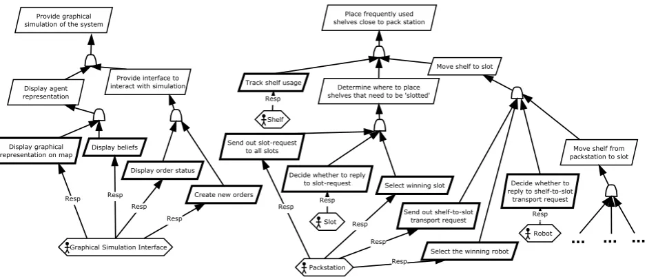
Identify System GoalsandPosoMAS-Task: Refine System Goals to RequirementsfromPractice: Goal-driven Requirements Elicitation). The entries relevant for this sprint are shown in the goal diagram in Fig. 5.1. They are summarised by the following extensions which are also used for sprint planning:
• Graphical Interface for representation of the system (display representations of robots, shelves, and
pack stations)
• Enable user input for orders (provide interface to interact with simulation)
• Tracking shelf usage for smart placement of shelves on slots (determine where to place shelves that need
to be slotted, track shelf usage)
• More mobility for the robots. (move shelf to slot)
• Multiple agents per type, i.e., multiple shelves and robots in the system (no explicit goal but necessary
for evaluation purposes)
The product backlog is the starting point for the Scrum Team for discussing the topics and estimating the effort of the requirements. The following shows an excerpt of the activities that have been tackled in the second sprint.
5.4.1. Sprint Planning. The Scrum activity “Sprint Planning” includes estimating the prioritised goals on the product backlog. Thus, the first step is the description of the highest priority backlog items by the Product Owner. If the Scrum Team has asked enough questions concerning the items to be confident to make appropriate estimations of their development effort, they start defining the goal for the sprint and estimating
4
Fig. 5.1: Excerpt of the goal diagram which defines backlog items on the product backlog. After the “Task Breakdown” the goal diagram is extended by the newly defined task on the sprint backlog. Slanted rectangles are goals, slanted rectangles with a thick border are requirements. Connections between goals as well as goals and requirements indicate a refinement translation. Hexagons represent agent types and connections annotated with “Resp” indicate that the agent type is responsible for the fulfilment of the requirement.
the items subsequently. For this purpose, the Scrum Team used the planning poker technique [30] where each team member proposes an estimate at the same time using numbered cards, the estimates are discussed, and the process is iterated until a consensus is reached.
After the estimation of all product backlog entries, the requirements with the highest priority have been selected for the sprint respecting the overall velocity of the Scrum Team. The velocity of a Scrum Team is
estimated by the team itself (PosoMAS-Task “Estimate Velocity”). It determines how much work the Scrum
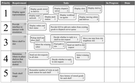
Team can take on in that iteration. Each of the requirements has been broken down into tasks according to the PosoMAS-Task “Task Breakdown”. Tasks are finer grained units of work for a requirement and are also estimated. While some tasks have been taken verbatim from the goal model (e.g., “Select winning slot”), some new tasks have been added. These are necessary to break down large requirements into manageable chunks for the sprint backlog. In AMHOFS the goal “display agent representation” has been divided into eight tasks which can not be found in the goal model but are represented on the task board. The complete sprint backlog of the current sprint is shown in Fig. 5.2.
5.4.2. Sprint Activities. During the sprint the Scrum Team performed several PosoMAS-Activities in
order to achieve the requirements in the sprint backlog.
Activity: Design System Dynamics The main aim in the current sprint is to implement a graphical
representation of the system and improve the movement of the robots and the shelves.
Priority Requirement Todo In Progress Done
1
2
3
4
5
Display agent representation Provide interface to interact with simulationMove shelf to slot
Determine where to place shelves that need to be slotted
Track shelf usage
Display road network 5
Display dispatch server 2
Display pack station 3
Display shelves 2 Display goods stored
in shelves 5
Display workload
on agents 5 Display moving robots and shelves 8
Display orders and
their status 5 Provide GUI to add new orders from existing goods to dispatch server queue 8
Pickup shelf and place shelf 3
Decide whether to reply to a shelf-to-slot request 2
Send out shelf-to-slot request 2 Find path to
slot 5 Select the winning
robot 1
Move one step from slot neighbour slot 3 Display slots
5
Send out slot-requests to all slots 1
Select winning slot 2 Decide whether to reply
to slot request 2
Remember number of visits at each pack station for each shelf 2
Save history of stored goods for each shelf 2 13
40
13
5
5
Fig. 5.2: Sprint backlog/task board at the beginning of sprint 2. Requirements have been estimated using planning poker first. Then they have been broken down into tasks which have been estimated in turn. This ensures that the original estimate was sensible. Note that task estimates must not necessarily add up to the estimate of the requirement.
PosoMAS-Task: Define Agent Capabilities and Behaviour fromPractice: Evolutionary Agent Design:
All AMHOFS agents inherit from an abstract class calledBaseAgentBDI. This class implements the basic
func-tionalities for AMHOFS agents, e.g., the generic interaction protocol. Each specific agent type, e.g., the robot (responsible for transporting the shelves from point A to B), extends this base agent by specific functionality and a graphical representation. The capabilities and behaviours of the robot agent defined and implemented in the current sprint encompass the movement from a start to an end position. This movement could be carried out with or without a shelf on top. The outcome of the definition of the capabilities is shown in Fig. 5.3 as a BDI agent model for the robot. In a nutshell, a movement of a robot is trigged by some external event (change
of a belief) that leads to a new goal, i.e., a MoveGoal. This goal in turn triggers a plan that is executed until
the robot has reached the desired point. For implementing the plan the movement is fragmented into steps that in turn are realized as goals with regarding plans.
The Scrum Team made the design decision that each agent is responsible for its graphical representation and that it is always up to date. PosoMAS does not prescribe to use a specific framework to implement the application but is open for the usage of such one. In our case study we use JADEX, a MAS framework [35]. Within this framework it is easy to add a graphical representation to an agent by adding a reusable building bloc, a capability called avatar, which enables the developer to define the appearance of the agent and to update its believes in the graphical user interface. This capability is added to the generic BaseAgentBDI and automatically all types of agents inherit the link to their environment and only have to specify their concrete appearance properties.
Activity: Develop Solution Increment The aim of the activity is to build the control centre for
y
«belief»+moves : AMHOFSMove [0..* ] «belief»-currentSlot : IComponentIdentifier
«agent»
RobotBDI
-pathQueue : IComponentIdentifier [1..*]{ordered} -destinationSlot : IComponentIdentifier
«goal»
MoveGoal
+executeMove( goal : MoveGoal ) : boolean
«plan»
MovePlan
+executeStep( goal : StepGoal ) : boolean
«plan»
StepPlan
-nextSlot : IComponentIdentifier
«goal»
StepGoal
execute until currentSlot = destinationSlot
SubGoal created for each nextSlot in pathQueue
execute until succeeded or waiting mode active triggered by belief change: moves
Fig. 5.3: Design of the movement capability of a robot agent as a UML diagram annotated by stereotypes. These stem from an ad-hoc BDI meta-model realised as a UML profile.
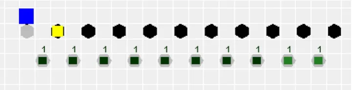
Fig. 5.4: The slots form a road network. A robot may move horizontally and vertically between the slots. The grey hexagons represent slots that are available for shelves while the black hexagons are reserved parking spaces for idle robots. Yellow squares represent robots. The shelves are shown as smaller black squares with numbers that display the number of goods placed on that particular shelf. The pack station is represented by a blue square.
addition the extensions of the generic protocol must be implemented.
Task: Implement Solution from the EPF base method content: To fulfil the assumption that all orders in the AMHOFS system are satisfiable the user must be prevented from creating invalid orders and assign them to the system. Therefore, a pre-defined list of available goods has been defined. The “ERP system” simulated by the user is consequently not able to demand any good that is not available. In addition, the shelves are assigned with an initial set of goods. An order is processed by the dispatch server that handles the order and distributes tasks to the shelves.
The generic interaction protocol has been adapted for the smart placement of shelves after being used at
a pack station. Therefore, the decision parameters were added as defined in thePosoMAS-Task: Design Agent
Interactions.
5.4.3. Sprint Review. During the review a deadlock between two moving robots has been detected that
is a result of missing fallback procedures in the road network. The bug has been added to the product backlog with a rather low priority, because the overall impact of the bug is categorized as low. Furthermore, the review led to new requirements on the backlog: the graphical representation of the shelf, robot, and slot should be enriched with more details viewable in a context menu. As the outcome of sprint 2 is a shippable build of the graphical representation (see Fig. 5.4) and more flexible robots, the sprint was accepted by the Product Owner.
5.4.4. Sprint Retrospective. Reflecting the sprint the Scrum Team identified a major concern in the
at initialisation is also randomised. As a consequence the team agreed on putting more effort in designing test scenarios for the requirements on the sprint backlog to improve the test process. Furthermore, the effort of testing has to be taken into account during the task estimation process. One of the successes of the sprint has been the use of the generic interaction protocol. The effort for designing this protocol for the agents paid off during the development of further interaction mechanisms.
5.5. Lessons Learned. The development of PosoMAS and PosoMAS-Scrum and the accompanying
vali-dation provided a number of lessons that have been integrated in the process and its documentation. First and
foremost, the distinction ofarchitecture areas is vital for the creation of a modular, flexible design. Many of the
problems with the initial system design in early iterations were caused by misunderstandings about which parts of the design were on the agent level, which on the system level and in the environment, and which are part of the organisation design. Our observations with developers being rather inexperienced with agent systems and a rather coarse division of the architectural areas showed a tendency to develop a centralised system structure as in an object-oriented approach. That made it difficult to assign responsibilities to agents and to identify necessary communication flows. In contrast, an early and clear distinction, as we outlined it, helps guide the developers during the first iterations and leads to better results in forming a suitable agent-oriented system architecture. These areas have thus been discriminated more thoroughly and according tasks and guidance have been disentangled. This not only leads to a better separation of concerns in the resulting design, but in the method content as well.
Second, the concept of scope and thus of the system boundary has been overhauled and extended from
the guidance provided by existing AOSE processes. Essentially, everything outside the scope the system has to interact with can not simply be ignored but assumptions must be captured and the environment has to be modelled accordingly. This can, at least partially, be done in the requirements engineering activities, but
also impacts the design of the system. The Practice: Agent Environment Design has been updated in
response to these necessities. Miller et al. [29] advocate—based on their own experiences—to delay the decisions of defining system boundary as long as possible and at least to wait until the stakeholders have formed a shared understanding of the problem. PosoMAS-Scrum supports delaying the decision. As long as the requirements and the necessary design documents contain the vital model elements, the point in time where the decision regarding the system boundary is made is fully up to the developers. Nevertheless, since the system boundary directly influences the project scope and thus development time and costs our experiences indicate that delaying the decision is not always beneficial.
Finally, a specialised UML profile containing stereotypes for agents, methods that are part of an agent’s interface, and external components was introduced to mark specific concepts in the agent and system models, thus clarifying the semantics of the modelling elements.
Third, the combination of goal-driven requirements engineering and Scrum warrants a more detailed dis-cussion. While the approach described here worked well enough in the context it was used, there are a number of challenges that were discovered. One aspect is that coming to an initial version of the goal model that can be used as the source for the first product backlog is challenging. The life cycle we chose allows for an initial-isation phase that can contain a longer initial requirements engineering effort. How long this takes in practice was, however, underestimated. Furthermore, when elements from the goal model are transferred to the Sprint Backlog, they should be locked in the goal model. If not, the Product Owner might change the goals that the team is currently working on and this change can go undetected until the next Sprint Planning session when the artefacts are synchronised. As mentioned before, this area is subject of future work.
6. Related Work and Comparison. This section introduces the most relevant existing AOSE
method-ologies and then compares a selection of these to PosoMAS-Scrum. A more in-depth comparison and additional information about these other processes can be found at http://posomas.isse.de.
6.1. Characteristics of Existing AOSE Methodologies. There are a number of AOSE methodologies
reference point for comparing AOSE methodologies. The processes selected below have been mainly chosen due to the currentness of the published method content. A recent overview of agent-oriented design processes is presented in [12] where a number of processes are cast in the IEEE FIPA Process Documentation Template but
the book offers no significantnew method content or a qualitative comparison of the methodologies.
In the following, we refer to the requirements defined in Sect. 2. As discussed there, these requirements make sense for many circumstances but we make no claim for their generality for specific development efforts. They aim at providing flexible method content and support for the system class we are concerned with. If these requirements are relevant for a specific development effort must be checked before a decision for a process is made.
ThePrometheusmethodology [32] combines specification, design, and implementation in a detailed pro-cess and is commonly accepted as one of the most mature AOSE approaches (cf. [44, 2, 13]). Prometheus uses a bottom-up approach for the development of multi-agent systems with BDI agents. While the focus on BDI is often lauded [2, 13], some authors criticise that this constitutes a restriction of application domains [44].
According to [32], however, only a subset of Prometheus is specific to BDI. Still,independence is thus limited.
The process has no notion of agent organisation and focuses solely on interactions between the agents. This
also limits theseparation of architecture domains. A main feature are detailed guidelines that support the
de-velopment steps, as well as support for validation, code generation, consistency checks, testing and debugging.
These guidelines promote extensibility but it is unclear how the process can be adapted to different process
lifecycles.
ADELFE has been specifically developed for the design of adaptive multi-agent systems (AMAS) with
emergent functionality [7]. The methodology follows the Rational Unified Process (RUP) closely and uses UML and AUML, an extension of the UML meta-model with agent-specific concepts [4]. The method content for
ADELFE is provided in SPEM format, making itextensible and reusable. It follows principles from the AMAS
theory as well as classical object-oriented approaches. Adherence to the AMAS theory is also the main criteria when assessing the applicability of ADELFE for a specific system: it should have a certain complexity and should be open. Additionally, the development of algorithmic solutions to the core problems is an integral part of the process and therefore, the approach is mainly suitable when the algorithms are not known yet. This
severely limits the methodology’s independence. If an agent reaches a certain complexity in ADELFE, it is
treated as a separate AMAS, thus providing a focus on interaction between agents and agent organisations.
This also provides some separation ofarchitecture domains, but the process does not provide guidelines on the
separate, principled modelling of these domains.
ASPECSfocuses on complex systems with an emphasis on holonic organisations [10] based on the PASSI
methodology. A holon is here defined as “[. . . ] self-similar structure composed of holons as sub-structures”. The organisation into holons is captured in a meta-model that is used for the definition of the system structure. An important principle leveraged in ASPECS is the possibility of stepwise refinement of the holons. Like ADELFE,
the methodology therefore has drawbacks w.r.t.independence and, in addition, relies on a specific meta-model.
It is, however, extensible since the method content is available online. Bothseparation of architecture domains
and a focus oninteractions are ensured.
TheMultiagentSystemsEngineering methodologyMaSEincludes a development life cycle starting from
the initial system specification and including implementation and deployment [15, 2, 13]. It has been applied in
several research projects and has been lauded for its comprehensibility [44]. MaSE isindependent of a specific
agent architecture and can therefore be applied to heterogeneous systems [2]. A strength of the methodology is the way agent interactions and protocols are defined. Drawbacks are the complex description of concurrent tasks, the absence of models for the environment and agent behaviour, and missing specification tools for agent adaptivity [1, 13]. In addition, the methodology was difficult to customise and organisational factors were
not considered [14]. Based on this criticism, O-MaSE and “agentTool”5 have been developed [14]. They
provide a method engineering framework with which method fragments specified as SPEM1 activities can be
composed. The method content is based on a common meta-model and focuses mainly on analysis, design,
and implementation. Organisations and the environment are now explicitly considered. Extensibility and
independence are limited due to the specialised tool required and due to the meta-model. O-MaSE provides no
5
overall system design activities, thus reducing theseparation of architecture domains.
INGENIAS [33] aims at the development of organisational multi-agent systems and is the descendant of
MESSAGE [8]. It uses meta-models to describe the relevant concepts in different aspects or “viewpoints” of a MAS, including organisation, agent, goals/tasks, interactions, and environment [33]. Relationships between the concepts for the different viewpoints are exploited to ensure consistency of the modelling. Meta-models are described in a specialised modelling language. The agents are based on BDI. INGENIAS is supported by
specialised tools for modelling and process customisation. While this limits theextensibility andindependence
of the methodology, it offers full support for separation of architecture domains and forinteractions between
agents and agent organisations. The methodology is supported by specialised tools, the “INGENIAS
Devel-opment Kit (IDK)” and the “INGENIAS Editor”6. INGENIAS originally uses the life cycle of the Unified
Process, allowing an iterative and incremental development, but a version using Scrum as a framework has been suggested [19]. Similar to PosoMAS-Scrum, the method content is embedded in the iterative-incremental lifecycle and supplemented by typical Scrum activities.
From the remarks above, it becomes clear that all AOSE methodologies support a different set of re-quirements and apply to different types of systems. A more detailed comparison between PosoMAS-Scrum, Prometheus, ADELFE, and INGENIAS-Scrum is shown below. However, it must be noted that not all require-ments apply to all development situations. For some teams, it might be helpful to have a meta-model available or support by a dedicated tool. Others do not require support for agent organisations since the scale of the system under development is low or more complex organisational structures are not needed. In such situations, PosoMAS may not be an ideal candidate and one of the other methodologies may be better suited. It is thus important to consider the actual requirements of the development effort before choosing a process [21].
6.2. Comparison between AOSE Processes. The validation of a software engineering process is
diffi-cult from a methodical point of view. Ideally, the process is tested in a productive environment for the creation of a software product with an experienced team of software engineers and developers who can compare the effort to previous experiences with other methodologies. Such an approach, however, is not feasible in the scope in which AOSE methodologies are created at the moment. Instead, we rely on qualitative evaluation and validation criteria. Tran et al. [45, 44] have introduced a catalogue of criteria that are used in Table 6.1 to show the characteristics of PosoMAS and to compare it to other approaches. These criteria are related to the support the methodologies give in different areas. To ensure that all relevant aspects of the development process are covered, Tran et al. identified 19 commonly used development steps that were confirmed to be necessary by a survey conducted among experts. The set of criteria can therefore be considered quite exhaustive.
It should be noted that such a comparison is not suitable to make a statement about which methodology is “better” in general, but rather serves as an aid in deciding which of the methodologies is suitable in a specific development project. If such a project, e.g., requires explicit support for proactivity, Prometheus, ASPECS, or INGENIAS-Scrum might be more suitable than PosoMAS-Scrum. On the other hand, if the focus is on the development of an open system, PosoMAS-Scrum has advantages. Likewise, while Table 6.1 might give the impression that ASPECS covers more criteria and is therefore suitable in all situations in which PosoMAS-Scrum can be applied, this is not actually true since ASPECS prescribes the use of holons and a specific meta-model that is not suitable to all projects. Ideally, a situational method engineering approach (cf. Sect. 3.1 would identify method content from different methodologies that fits the project and combine it. Unfortunately, this is difficult since most processes lack a readily available machine-readable standardised process description.
Table 6.1 only captures if a process has explicit supporting content for a certain criterion. It is, e.g., possible to build proactive systems with PosoMAS even though the process does not include specific support for them. The process website contains a detailed description of the criteria and comparisons under different aspects and for additional methodologies.
The basis for the evaluation of PosoMAS-Scrum is the development effort described in Sect. 5. The OpenUP-based version of PosoMAS has been evaluated with two simulated case studies, one of which — a power manage-ment example — is available online along with a detailed description and a selection of artefacts. Information about the other processes has been extracted from the relevant literature. We present the characteristics of
6
![Fig. 4.1: Ambler et al.’s Agile System Development life-cycle (SDLC) [3] as used for PosoMAS-Scrum](https://thumb-us.123doks.com/thumbv2/123dok_us/8746180.1747373/9.595.68.535.118.257/fig-ambler-agile-development-cycle-sdlc-posomas-scrum.webp)
![Table 6.1: Characteristics of PosoMAS-Scrum, Prometheus, ASPECS, and INGENIAS-Scrum based on [45, 44,32, 10, 19, 18, 12]](https://thumb-us.123doks.com/thumbv2/123dok_us/8746180.1747373/19.595.59.536.160.579/table-characteristics-posomas-scrum-prometheus-aspecs-ingenias-scrum.webp)
