Design and experiment of a bionic vibratory subsoiler for banana
fields in southern China
Zhang Xirui
1,
Wang Chao
1,
Chen Zhishui
1*,
Zeng Zhiwei
2 (1. College of Mechanics and Electrics Engineering, Hainan University, Haikou 570228, China; 2. Department of Biosystems Engineering, University of Manitoba, Winnipeg, Manitoba, Canada, R3T 5V6)Abstract: Subsoiling is essential in the tillage of banana planting, as banana plants have a fairly sturdy pseudostem and wide row spacing while soil tends to be compacted. In this study, a bionic vibrating subsoiler for banana fields was developed, verified, and evaluated. The vibrator was designed based on crank-rocker mechanism while the bionics design was used for subsoiler development. The forces on the susboiler were analyzed to verify the strength of the subsoiler tine. To test the performance of the subsoiler, field tests were conducted to measure the draft force and fuel consumption. There was approximately 14% reduction in the draft force and 22% increase in the fuel consumption in vibrating mode compared with that in non-vibrating mode. In conclusion, the study results could be applied in China’s tropical agricultural regions.
Keywords: vibratorysubsoiler, tillage, simulation, bionics, banana field
DOI: 10.3965/j.ijabe.20160906.1923
Citation: Zhang X R, Wang C, Chen Z H, Zeng Z W. Design and experiment of a bionic vibratory subsoiler for banana fields in southern China. Int J Agric & Biol Eng, 2016; 9(6): 75-83.
1 Introduction
Subsoiling, as an important component of vertical tillage, is designed to eliminate the compaction created by horizontal tillage tools such as sweeps and shovel implements. It is a crucial process in conservation tillage which minimizes soil surface disturbance without inversion, while shattering subsoil structure[1]. Subsoiling breaks up compaction layers, promotes aeration, limits runoff, and increases water holding capacity which helps soil retain moisture. It also alleviates the problem of excessive soil strength by
Received date: 2015-05-07 Accepted date: 2016-10-07
Biographies: Zhang Xirui, PhD, Associate Professor, research interests: conservation tillage and tropical agricultural machinery, Email: [email protected]; Wang Chao, Master student, research interests: tropical agricultural machinery, Email: [email protected]; Zeng Zhiwei,Master student, research interests: conservation tillage, Email: [email protected].
*Corresponding author: Chen Zhishui, Associate Professor, research interests: tropical agricultural machinery, mailing address Hainan University, Haikou, Hainan 570228, China. Email: [email protected].
reducing impedance to root penetration and improving root growth. And subsoiling can significantly enhance soil conservation, water infiltration, and crop yield has been proved[2-5].
There are mainly two types of subsoilers: non-vibrating (conventional subsoiler), and vibrating (oscillating subsoiler)[6-8]. Vibrating subsoilers can reduce the draft force, but requires higher overall power than non-vibrating subsoilers since the vibration mechanism demands driving power[9,10]. In the past decade, studies have been conducted on effects of subsoiling on crop growths and soil properties[11,12], and
high-horsepower tractor for pulling a set of subsoilers. Subsoilers have been evolved to low soil disturbance and low energy input. One of the concepts for design of subsoilers is using the principle of bionics. Soil-burrowing animals, for example, ant (Formicidae), house mouse (Mus musculus), and pangolin (M. pentadactyla), have strong digging legs or claws through natural evolution and adaptation of the living surroundings. Those legs and claws have optimal geometrical features and biomechanical properties, including anti-adhesion, anti-friction, and anti-abrasion properties. Researchers have mimicked the geometrical shapes and curvature characteristics of house mouse’s claw in the design of subsoilers to optimize the performance[18,19].
This research intended to apply the bionic technology and vibrating concept to study the drag reduction performance of the subsoilers, as mentioned above. The research goal was to develop a bionic vibrating subsoiler for banana crop field and study the combined effects of vibrating and bionic of subsoilers, and to promote agricultural mechanization and conservation tillage in China’s tropical agricultural regions. The specific objectives of the study were to (1) develop a subsoiler and its vibrating mechanism based on the bionics design concept, (2) perform force analysis on the susboiler, and (3) evaluate the overall performance of the subsoiler in terms of the draft force and fuel consumption.
2 Material and methods
2.1 Agronomic requirements of subsoiling
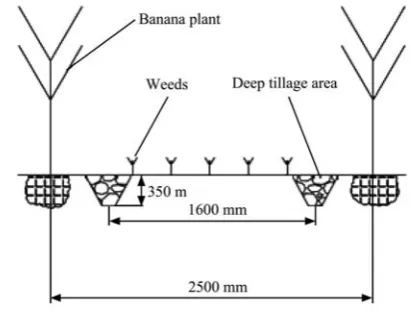
The schematic diagram of subsoiling shows the agronomic requirements of the subsoiler designed for banana fields (Figure 1). As banana plants are very tall, subsoiling has to be performed between the plant rows. Banana plants typically have a row spacing of 2500 mm. The subsoiling can be conducted between plant rows with a double-shank subsoiler. The shank spacing was set to 1600 mm, which was considered an appropriate distance away from the banana roots, and at the same time close enough to promote root development and plant growth. The working depth of subsoiler was determined to 350 mm[20,21] based on the soil layer distribution and
hardpan location in banana fields.
Figure 1 Schematic diagram of subsoiling for banana fields
2.2 Machine description
The subsoilers for wheat, corn, and soybean have been studied quite intensively by using experimental methods and numerical analyses, which provided detailed reference information when designing general components of the subsoiler for banana fields. Therefore, this study only focused on the design and simulation of key components of vibratory subsoiler, i.e. the vibrator and the subsoiler (including the shank and the tine). The feature of double-shank with vibration was adopted to reduce the draft force[22].
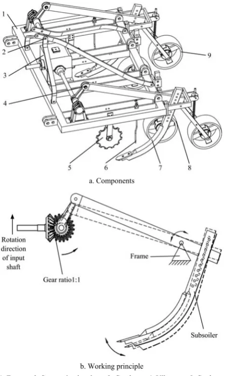
The main components of the subsoiler include frame, gearbox, a pair of suspension brackets, vibrators, coulters, grass breakers, shanks, gauge wheels, and press wheels (Figure 2a). The subsoiler was mounted on the tractor through a three-point hitch. Two vibrators were located symmetrically from the central gearbox at a distance of 1600 mm. Other parameters of the subsoiler are summarized in Table 1.
a. Components
b. Working principle
1. Frame 2. Suspension bracket 3. Gearbox 4. Vibrator 5. Coulter 6. Grass breaker 7. Shank 8. Gauge wheel 9. Press wheel
Figure 2 Schematic diagram of subsoiler for banana fields
Table 1 Parameters of the vibratory subsoiler
Parameters Design value
Dimensions (L/W/H)/mm 1950/2000/1230
Weight/kg 250 Power/kW 37-50 Vibrating frequency/Hz 0-9
Working rows 2
Working row space/mm 1600 Working depth/mm 250-350
Working speed/km·h-1 2.5-6
Efficiency/hm2·h-1 0.375-0.9
2.3 Vibrating system design
The vibrator consists of crankshaft, connecting rod, and rocker, which are shown in Figure 3. The function of the vibrator was to introduce the oscillation in the subsoiler in the longitudinal-vertical plane, i.e. moving forward, backward, upward, and downward.
The crankshaft was connected with output shaft of the gearbox by coupling at one end, and supported by a bearing block at the other end. The crankshaft was made of ductile iron (QT400-10), which had high
strength and toughness with high wear and shock resistance. The crankshaft length (L0) was determined
as 755 mm based on the row spacing (1600 mm) in the banana fields. The eccentricity of crankshaft, i.e. crank length (L1=40 mm), was determined empirically to
generate practical amplitude of the tine.
Note: 1. Crankshaft 2. Connecting rod 3. Rocker 4. Bearing block
Figure 3 Schematic diagram of the vibrator
A connecting rod was hinged between the crank and the rocker with rod cap and pin connection, respectively. As the main load-bearing component in the crank-rocker mechanism, the connecting rod was made of Q235 steel plate with a thickness of 20 mm. The surface hardness of steel after heat treatment was approximately 302B. The working length of the connecting rod L2 was chosen
as 200 mm. The working distance between the crank and the rocker pivot L4 was 994 mm, which was
determined by the location of fulcrums on the frame. Rocker was made of Q235 steel plate with hot-rolling and cold-drawing process. The dimensions of the rocker was 1200 mm×80 mm×30 mm (length×width×thickness), while the effective length within the crank-rocker mechanism was L3. According to the Grashof’s criteria
of existing crank in four-bar linkage, the conditions listed below needs to be satisfied:
1 4 2 3
3 4
L L L L
L L
+ ≤ +
⎧ ⎨ ≤
⎩ or
1 3 2 4
4 3
L L L L
L L
+ ≤ +
⎧ ⎨ ≤
⎩ (1)
Substituting the values and solving the equation set (1) and that L3 should be greater than 834 mm but less than
1154 mm was obtained. Therefore, the effective length of the rocker was chosen as 885 mm.
2.4 Subsoiler design
2.4.1 Shank design
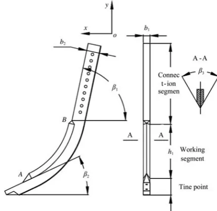
was developed through quantitatively mimicking the geometrical shapes and curvature characteristics of a house mouse’s digging claw to reduce the draft force of subsoiler. The shank was constituted with a working segment in the middle and two connecting segments at each end, which were used for connecting the rocker and the tine (Figure 4). The #45 steel rod was used to forge the shank. The curve of the working segment was adapted from the amplifying curve of house mouse's claws. The cutting edge of working segment was shaped and sharpened to easily move in the soil. Two connecting segments had rectangular cross-sections and joined with working segments smoothly.
The fitted curve f1 of the house mouse digging claw
was presented as followed[23]:
2 3
0.2272 5.33522 0.62316 0.02478
y= − x+ x − x (2)
The shank rake angle was obtained between 70.7°- 75.6° through the motion analysis of the vibrator. The average value of 73.15° was used. Therefore, the negative tangent value of the shank rake angle was the slope of the tangent line of the working segment upper end, which was close to the rocker.
The working depth and speed of the subsoiler, as well as the soil texture and properties, affected the optimal value of penetrating angle. The common value was within the range of 20°-45° to minimize the working resistance. In consideration of the working conditions in banana fields and the angular fluctuation of 4.9° due to the vibration, the average value of penetrating angle was set to 25°. In other words, the bottom end of the working segment curve had a slope of negative tan 25°.
The equations at two end points, namely points A′ and B′, are as follows:
2 3
d
tan 25 d
0.2272 5.33522 0.62316 0.02478 y
x
y x x x
⎧ = −
⎪ ⎨
⎪ = − + −
⎩
o
(3)
2 3
d
tan 73.15 d
0.2272 5.33522 0.62316 0.02478 y
x
y x x x
⎧ = −
⎪ ⎨
⎪ = − + −
⎩
o
(4)
Solving the Equations (3) and (4) and obtained the coordinates of A′ (6.19801, –14.80173) and B′ (1.83165, –7.60667). The working curve of subsoiler (f2) was
linearly amplified from the fitted curve of claws (f1).
Assuming the amplification coefficient was n, the corresponding coordinates of A′ and B′ in f2 were A
(6.19801n, –14.80173n) and B (1.83165n, –7.60667n), respectively. The maximum subsoiling depth of 350 mm (Table 1) required the vertical height of working segment (h1) to be 270 mm, in consideration of the height
of the bottom connecting segment and the tine. Thus, the height difference between points A and B was 270 mm, i.e. 14.80173n–7.60667n=270, which gave an amplification coefficient (n) of 37.52575. The working curve (f2) for shank was:
2 3
8.52585 5.33522 0.01661 0.000018
y= − x+ x − x (5)
where, 1.83165n≤x≤6.19801n, i.e. 68.73≤x≤232.58 mm. The cross-section views of the working segment in Figure 4 showed the cutting angle at the front and the rectangular shape at the back. The cutting angle β3 of
60° combined with the shank width b1 of 40 mm and
thickness b2 of 80 mm were used to optimize the
subsoiler cutting performance while guaranteeing the tool strength.
Note: β1 is the shank rake angle, (◦); β2 is the penetrating angle, (◦); β3 is the cutting angle of the working segment, (◦); b1 is the width of the shank, mm; b2 is the thickness of the shank, mm; h1 is the length of working segment in the vertical direction, mm.
Figure 4 Schematic diagram of the subsoiler shank 2.4.2 Tine design
structure with a strong burrowing ability was chosen, while a parabolic curve was used for front and a rectangular shape was used for the back (Figure 5). Considering the heavy residue in banana fields, two countersunk screws were placed in the countersink holes to fasten the tine at the tip of shank. The flat surface of the tine improved soil and residue flows and prevented tool from clogging. The tine was made of 65Mn steel with post-quenching.
Note: β4 is the cutting angle of the tine, (◦); h2 is the thickness of the tine tip, mm;
h3 is the thickness of the tine base, mm; L is the length of the tine base, mm; b3 is the width of the tine, mm.
Figure 5 Schematic diagram of the subsoiler tine The parabolic tip can be described using the following equation from the coordinates shown in Figure 5.
2 3 3
3
0.2887 ,( )
2 2
b b
y = b x − ≤ ≤y
(6)
The draft force and susbsoiling width were both positively related to the width of the tine. To achieve desired working width under acceptable soil resistance, the width of the tine b3 was set to 60 mm. The length of
the tine base L was set to 150 mm to ensure the reliability of the connection between the shank and the tine.
Decreasing the thickness of the tine tip would reduce soil resistance during cutting operations. However, a curved shape was relatively easy to create using a thin tip. The thickness h2 was set to 2 mm for the tine tip. The
thickness of the tine base h3 was chosen to 12 mm in
consideration of strength as well as light weight.
The cutting angle of the tine affected the cutting resistance in soil, while decreasing the cutting angle reduced the overall strength. The cutting angle of the tine was usually less than the penetrating angle to prevent compaction during subsoiling operations. Considering the fluctuation of penetrating angle, the cutting angle of the tine β4 was determined to be 18°.
2.5 Force analysis
2.5.1 Subsoiler force analysis
The shank and the tine are the major load carrying components of the subsoiler, and the tine encounters a more complicated and unfavorable stress situation in the sub-soil surface. Thus, the force analysis was conducted on the tine via simulation to validate its working state in terms of material strength properties.
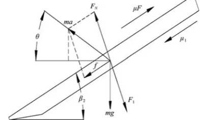
Under the action of vibrating and cutting tine, the forces acting upon the clod located above the tine includes gravity, accelerating force, shear force, and the normal and frictional force due to the interaction with the tine and the front soil clod (Figure 6). The soil was assumed to be homogeneous and free of stones which had a negligible shear force. The fluctuation of 4.9° in penetrating angle would not affect the force analysis. Thus the average penetrating angle of 25° was used for simplicity.
Note: F1 is the normal force from the tine, N; F2 is the normal force from the front soil clod, N; Fa is the accelerating force, N; β2 is the penetrating angle, (◦);
γ is the rake angle of the failure plane, (◦); μ is the friction coefficient between soil and the tine; μ0 is the friction coefficient of soil; C is the soil cohesion, N·m-2;
S is the area of the failure plane, m2; a is the acceleration of the clod, m·s-2; a
x is
the acceleration of the clod in horizontal direction, m·s-2; a
y is the acceleration of
the clod in vertical direction, m·s-2.
Figure 6 Force analysis of the clod above the tine
The mechanics equilibrium equations in the horizontal and vertical directions of the clod are based on Newton’s second law:
1 2 1 2 2
0 2
cos sin cos
( a )sin x
F F F
F CS F Vg Va
β μ β γ
μ γ ρ ρ
+ +
1 2 1 2 2
0 2
sin cos sin
( a ) cos y
F F F
F CS F Va
β μ β γ
μ γ ρ
+ −
− + + = (8)
where,ρ is the soil density, kg/m3.
The acceleration of the clod under the impact of the tine can be expressed by the following equations:
ay=asinθ (9) ax=acosθ (10) a=a′
(11)
where, a′ and a are the acceleration of the tine and the clod respectively, m/s2.
The accelerating force of the clod based on the Newton’s second law is:
1
d d
a
v
F m
t
=
(12) where, m1 is the mass of the clod, kg.
The movement of the clod was simplified as a uniformly accelerated motion:
2
d d
v v
t = t (13)
0 1cos 2 2cos 0
v −v β −v γ = (14)
2sin 1sin 2 0
v γ−v β = (15)
The speed increased from zero to v2 within the
accelerating time (t). The vertical amplitude of the tine was negligible in comparison with the subsoiling depth. Therefore, the mass of the clod under acceleration was approximated as the mass of the soil disturbed by the subsoiler, which was calculated as:
1 3 0
m =ρb hv t (16) where, v0 is the working speed of the subsoiler, v0=
2.5-6.0 km/h (0.7-1.7 m/s).
Solving the Equations (12) to (16) simultaneously and get the expression of the accelerating force as:
2
3 0
2
1 1
sin ( )
tan tan
a
b hv
F ρ
γ
β γ
=
+
(17)
The force acting on the tine could be partitioned into gravity, and the normal and frictional force from the interaction between the clod and the shank (Figure 7). The mechanics equilibrium equations in horizontal and vertical directions of the tine are:
1 N 1
f =μF −μF (18)
2 2
sin sin( )
f +mg β =ma′ θ β+ (19)
Note: FN is the normal force from the shank, N; F1 is the normal force from the clod above, N; f is the resultant friction force, N; β2 is the penetrating angle, (◦);
θ is the angle between the tine acceleration and the horizontal plane, (◦); μ is the friction coefficient between the clod and the tine; μ1 is the friction coefficient between the tine and the shank; m is the mass of the tine, kg.
Figure 7 Force analysis of the tine
2.6 Field tests
Field performance tests of the subsoiler prototype were conducted in the banana fields, which locate in the Baodao Village, Danzhou City, Hainan Province, China. The plant spacing and row spacing was 1400 mm and 2500 mm, respectively. The average diameter of the pseudostems and the height of the plants were 375 mm and 2500 mm, respectively. The soil was sandy clay loam (58% sand, 20% silt, and 22% clay). The average moisture content of the soil within the depth range from 0 to 400 mm was 30.3%.
the fuel consumption was determined.
3 Results and discussion
3.1 Subsoiler force analysis
The mass of the clod was a product of the soil density and the volume of the soil being supported by the tine, which was the volume of a frustum-like geometry (Figure 7). The area of the failure plane (S=129000-225000 mm2) and the volume of the clod (V=23420000-49840000 mm3)
within the range of subsoiling depth (h=250-350 mm) were obtained through three dimensional (3 D) modeling. The soil density (ρ=1150 kg/m3) and cohesion (C = 20000-40000 N/m2) in the banana field were measured using standard methods. The friction coefficient between the tine and the shank (μ1=0.15), the distance between the tine and the rocker pivot (r=745 mm), and the mass of the tine (m=0.897 kg) were also measured. The friction coefficient between the tool and the soil:
μ =0.4-0.6[24], and that of the soil: μ0 =0.56[25], as well as
the rake angle of the failure plane: γ=52°[26] were
obtained from the literature. The angle between the tine acceleration and the horizontal plane was calculated as
θ=θ3–90°–β1+β2=27.24° when the tine acceleration (a)
and the rocker angular acceleration (α3) had maximum
values of: amax=130.2564 m/s2 and α3max=174.8408 rad/s2.
Substituting those values into the Equations (9) to (11) and (17) to (19) and simultaneously solving for the applied forces experienced by the tine, the maximum value of the normal forces and friction forces on both top and bottom sides of the tine were F1max=6525 N, FNmax=26716 N, μF1 = 3915 N, and μ1FN = 4007 N. 3.2 Field test results
The draft force was sampled per second during
operation and plotted in Figure 8. The vibrating subsoiler had relatively smaller draft force at almost all the sampling points, which implied that the vibration reduced the draft force. However, the fuel consumption per unit area in Table 2 showed that the vibrating mode consumed more fuel than the non-vibrating mode. The reduction coefficient of draft force (ηr) and the increase coefficient of fuel consumption (ηo) were calculated as follows:
e
100%
P P
P
η = − v×
r
e
(20)
v
= e 100%
o e
Q Q
Q
η − ×
(21)
where, the subscripts v and e represent vibrating and non-vibrating modes, respectively.
Figure 8 Draft force under vibrating and non-vibrating modes at subsoiling depth of 400 mm
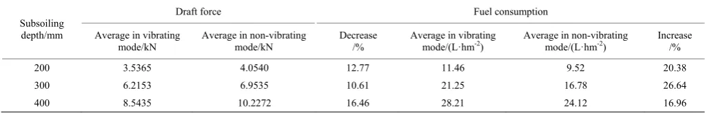
The results in Table 2 showed that under the vibrating mode, the draft force was reduced ranging from 10% to 17%, whereas it increased the fuel consumption ranging from 16% to 27% depending on the working depths. These findings occurred under the working speed of 1 m/s and PTO of 540 r/min.
Table 2 Comparisons of draft force and fuel consumption at different subsoiling depths
Subsoiling depth/mm
Draft force Fuel consumption
Average in vibrating mode/kN
Average in non-vibrating mode/kN
Decrease /%
Average in vibrating
mode/(L·hm-2) Average in non-vibrating mode/(L·hm-2) Increase /%
200 3.5365 4.0540 12.77 11.46 9.52 20.38
300 6.2153 6.9535 10.61 21.25 16.78 26.64
400 8.5435 10.2272 16.46 28.21 24.12 16.96
4 Conclusions
The bionic vibrating subsoiler was developed based on the agronomic requirements of banana planting. The
field tests under the vibrating and the non-vibrating modes showed that the average draft force decreased by approximately 13% and the average fuel consumption increased by 21%, at the different depths, in case of vibration at a tractor speed of 1 m/s and PTO 540 r/min. The results are comparable to the 13%-18% draft force reduction of 1SZ-460 lever-type subsoiler[27] and
8.5%-39.5% draft force reduction of a bionic anti-drag subsoiler[28], which the combined effects of banana crop subsoiling similar to the separate application results of the bionic technology or vibrating concept for major crops (maize, wheat, rice, et al.) may be due to the shallow rooted characteristics and a wide distribution root systems of banana crop that caused a greater resistance need further research. Besides, the vibrating design reduced the draft force, whereas it required higher fuel consumption, which was similar to the findings of Zhang et al.[29] The method and power used to drive the
vibrator needs further research to balance the draft and energy requirements, and improve the overall efficiency. As the vibrating frequency and amplitude affected the magnitude of the draft, further understanding their relationship is also recommended.
Acknowledgments
This work was financed by the Special Fund for Agro-scientific Research in the Public Interest from the Ministry of Agriculture, China (Grant No.201503136), the National Natural Science Foundation of China (Grant No.51565010) and the National Natural Science Foundation of Hainan Province (Grant No.20163038). Thanks are given to Dr. Ying Chen from the Department of Biosytems Engineering, University of Manitoba, Canada for her assistance in the experiment.
[References]
[1] Ehlers W, Claupein W. Approaches towards conservation tillage in Germany. In: Carter M R (Ed.), Conservation Tillage in Temperate Agroecosystems. Lewis Publishers, Boca Raton, USA, 1994; pp. 141–165.
[2] Abo-Elnor M, Hamilton R, Boyle J T. Simulation of soil-blade interaction for sandy soil using advanced 3D finite element analysis. Soil and Tillage Research, 2004; 75(1): 61–73.
[3] Evans S D, Lindstrom M J, Voorhees W B, Moncrief J F, Nelson G A. Effect of subsoiling and subsequent tillage on soil bulk density, soil moisture, and corn yield. Soil Till, 1996; 38(1-2): 35–46.
[4] Mouazen A M, Ramon H. A numerical-statistical hybrid modelling scheme for evaluation of draught requirements of a subsoiler cutting a sandy loam soil, as affected by moisture content, bulk density and depth. Soil & Tillage Research, 2002; 63(3-4): 155–165.
[5] Harisson H P, Licsko Z J. Soil reacting wrenches and dynamics for three models of bent leg plows. Transactions of the ASAE, 1989; 32(1): 50–53.
[6] Sakai K, Hata S I. Design parameters of four-shank vibrating subsoiler. Transactions of the ASAE, 1993; 36(1): 330–336.
[7] Wang G, Jia H L, Tang L, Zhuang J, Jiang X M, Guo M Z. Design of variable screw pitch rib snapping roller and residue cutter for corn harvesters. Int J Agric & Biol Eng, 2016; 9(1): 27–34.
[8] Tong J, Moayad B Z. Effects of rake angle of chisel plough on soil cutting factors and power requirements: A computer simulation. Soil & Tillage Research, 2006; 88(1-2): 55–64. [9] Linde J V D. Discrete element modeling of a vibratory
subsoiler. Stellenbosch University of Stellenbosch, 2007. [10] Shchukin S G, Nagajka M A. Investigation of the soil
tillage process by vibratory subsoiler. Siberian Herald of Agricultural Science, 2015: 83–89.
[11] He J, Li H W, Mao N, Wang S D. Experimental study on combined operation of drilling and subsoiling for no-till maize. In: The 2004 CIGR International Conference, Beijing, China, October, 2004; pp. 188–193.
[12] Tijink F J, Van J P. Engineering approaches to prevent subsoil compaction in cropping systems with sugar beet. In: Horn R, vanden Akker J J H, Arvidsson J (Eds.), Subsoil Compaction. Advances in Geoecology, vol.32. Catena Verlag, Reiskirchen, 2000; pp. 442–452.
[13] Li X, Fu J F, Zhang D X. Experiment analysis on traction resistance of vibration subsoiler. Transactions of the CSAE, 2012; 28(1): 32–36. (in Chinese with English abstract)
[14] Li B, Xia R, Liu F Y, Chen J, Han W T, Han B. Determination of the draft force for different subsoiler points using discrete element method. Int J Agric & Biol Eng, 2016; 9(3): 81–87
[15] Mouazen A M, Nemenyi M. Finite element analysis of subsoiler cutting in non-homogeneous sandy loam soil. Soil & Tillage Research, 1999; 51(1-2): 1–15.
[16] Shmulevich I, Asaf Z, Rubinstein D. Interaction between soil and a wide cutting blade using the discrete element method. Soil & Tillage Research, 2007; 97(1): 37–50.
techniques of banana. Guangdong Agricultural Sciences, 2010; 37(10): 69–70. (in Chinese with English abstract) [18] Tong J, Chen D H, Tomoharu Y, Zhang S J, Ren L Q.
Geometrical features of claws of house mouse Mus Musculus and biomimetic design method of subsoiler structure. Journal of Bionic Engineering, 2005; 8(1): 53–63.
[19] Zhang J B, Tong J, Ma Y H. Simulation of bionic anti-drag subsoiler with exponential curve feature using discrete element method. Applied Mechanics and Materials, 2013; 461: 535–543.
[20] Linde J V D. Discrete element modeling of a vibratory subsoiler. Stellenbosch University of Stellenbosch, 2007: 49–53.
[21] Shahgoli G, Fielke J, Saunders C, Desbiolles J. Simulation of the dynamic behaviour of a tractor-oscillating subsoiler system. Biosystems Engineering, 2010; 106(2): 147–155. [22] Li L X, Ji H L. Nonlinear dynamics analysis of vibratory
subsoiler. Information Technology Journal, 2013; 12(15): 3224–3228.
[23] Chen D H. Typical bio-tribological structures and their biomimetic applications. Changchun: Jilin University, 2007.
[24] Gong H Y, Wang L Q, Xing X D. Modeling of the plow bodyof submarine plowing trencher and analysis of the soil cutting process. Journal of Mechanical Engineering, 2012; 48(19): 134–139. (in Chinese with English abstract)
[25] Zhou Y Q. Force Mathematical Model and Computer Simulation of the subsoiler. Zhengzhou: Henan Agricultural University, 2006.
[26] Mak J, Chen Y, Sadek M A. Determining parameters of a discrete element model for soil–tool interaction. Soil and Tillage Research, 2012; 118(5): 117–122.
[27] Li Y L, Liu B, Cui T, Zhang D X. Design and field experiment on 1SZ- 460 lever type subsoiler. Transactions of the CSAM, 2009; 40(S1): 37–40. (in Chinese with English abstract)
[28] Zhang J B, Tong J, Ma Y H. Design and experiment of bionic anti-drag subsoiler. Transactions of the CSAM, 2014; 45(4): 141–145. (in Chinese with English abstract)